warwick.ac.uk/lib-publications
Original citation:
Khoromskaia, Diana and Alexander, Gareth P.. (2017) Vortex formation and dynamics of
defects in active nematic shells. New Journal of Physics, 19 (10). 103043.
Permanent WRAP URL:
http://wrap.warwick.ac.uk/94684
Copyright and reuse:
The Warwick Research Archive Portal (WRAP) makes this work of researchers of the
University of Warwick available open access under the following conditions.
This article is made available under the Creative Commons Attribution 3.0 (CC BY 3.0) license
and may be reused according to the conditions of the license. For more details see:
http://creativecommons.org/licenses/by/3.0/
A note on versions:
The version presented in WRAP is the published version, or, version of record, and may be
cited as it appears here.
Department of Physics and Centre for Complexity Science, University of Warwick, Coventry CV4 7AL, United Kingdom E-mail:[email protected]
Keywords:active nematics, thinfilm, topological defects, spherical shell, active matter
Abstract
We present a hydrodynamic model for a thin spherical shell of active nematic liquid crystal with an
arbitrary con
fi
guration of defects. The active
fl
ows generated by defects in the director lead to the
formation of stable vortices, analogous to those seen in con
fi
ned systems in
fl
at geometries, which
generate effective dynamics for four
+1/2 defects that reproduces the tetrahedral to planar oscillations
observed in experiments. As the activity is increased and two counterrotating vortices dominate the
fl
ow, the defects are drawn more tightly into pairs, rotating about antipodal points. We extend this
situation to also describe the dynamics of other con
fi
gurations of defects. For example, two
+1 defects
are found to attract or repel according to the local geometric character of the director
fi
eld around
them and the extensile or contractile nature of the material, while additional pairs of opposite charge
defects can give rise to
fl
ow states containing more than two vortices. Finally, we describe the generic
relationship between defects in the orientation and singular points of the
fl
ow, and suggest
implications for the three-dimensional nature of the
fl
ow and deformation in the shape of the shell.
1. Introduction
Active liquid crystals[1–3](ALCs)have proved successful as a paradigm for living systems on the microscale, providing insight into processes like cell motility[4–6]and division[7–9], development of cell shapes[10,11], and growth of cell colonies[12]. Certain fundamental motifs have been developed such as the instability of uniformly aligned states, the emergence of spontaneousflows, the creation and self-propulsion of topological defects and the shear-thinning character of extensile gels. More recently another motif has emerged around confinement of ALCs, where the prominent feature is the emergence of stableflow vortices. For instance, confinement gives rise to a stable single vortex state in dense bacterial suspensions[13,14], active nematic suspensions[15,16]and cell monolayers[17,18]. Circulatoryflows are also characteristic of cytoplasmic streaming[6,16,19,20]. As the system size is increased such vortices become unstable[21]and turbulentflows develop, a prevalent feature in bulk activefluids[22–24]. In active systems with high frictional dissipation stable vortices can also arise in the absence of spatial confinement[25–27]. Recent experiments by Keberet alon microtubule-based extensile active nematics[28]are realisations of a different type of confined geometry, in which the ALC adheres to the surface of a vesicle. The primary behaviour reported is of four motile+1/2 defects in the orientation that undergo regular oscillations between tetrahedral and planar configurations. Here, we develop a hydrodynamic model for a spherical shell of ALC, with arbitrary defect configuration, andfind topologically stabilised vortices as a prominent feature of theflow, which reproduces the defect motion from experiments.
Defects in the director are unavoidable on the sphere because of its topology[29]. In the minimal situation there are four, all of strength+1/2. Such defects are known to self-propel in ALCs[30], which motivates a minimal description of their motion as a point particle dynamics, and such a model was shown to reproduce the main experimental observations[28]. We extend this to a hydrodynamic model in the confined geometry of a
thin spherical shell and show that the dynamics is characterised by the formation of two counterrotating vortices, one in each hemisphere, paralleling the vortex formation seen in other types of confinement
[13,16,31]. Theseflows reproduce the tetrahedral to planar oscillations of the four+1/2 defects that are found
22 May 2017
REVISED
17 August 2017
ACCEPTED FOR PUBLICATION
1 September 2017
PUBLISHED
31 October 2017
Original content from this work may be used under the terms of theCreative Commons Attribution 3.0 licence.
Any further distribution of this work must maintain attribution to the author(s)and the title of the work, journal citation and DOI.
in experiments and in point-particle models of the dynamics. The oscillations of four half-defects are found to be stable against additional half-defect pairs created randomly in larger shells. If the defects are instead induced at specific positions, it is possible to generate more complex, metastableflow vortex configurations. The
oscillations appear above afinite threshold of the activity, below which the defects form static configurations of distorted tetrahedra. Linear stability analysis captures the mode of deformation and the threshold for defect motion. As the activity is increased the two large vortices dominate theflow and the pair of+1/2 defects within each are pulled closer together in an effective attraction of like-charge defects. The thinfilm geometry also leads to new scalings for the defect speed and for the frequency of oscillations.
The dynamics of polar configurations with only integer strength defects is similar and wefind hydrodynamic attraction of pairs of aster-like+1 defects in extensile active nematic shells, but repulsion for vortex-like defects. The speed of defects in the polar case is shown to have different scaling than for nematic shells, in particular the type of motion does not depend on the radius in the former case whereas it does in the latter.
Just as there are defects in the directorfield there are also vortices and stagnation points in theflowfield, with a total winding of+2 according to the Poincaré–Hopf theorem[29]. There is a one-way relationship that assigns to a defect in the director aflow singularity whose winding number depends only on the defect’s topological strength. However, in general theseflow singularities are not sufficient to satisfy the Poincaré–Hopf theorem and additional vortices also arise in between the director defects. Except in situations of high symmetry their location cannot be simply predicted from the defect positions.
2. Model
We consider an active nematic in a thin spherical shell of thicknessh0and inner radiusR, withh0 R =e1. With tangential alignment of the nematic, as we exclusively consider, there are necessarily defects in the director field, which dominate the elasticity and the active stresses, generating thresholdless activeflows[32]. When the elastic relaxation of the directorfield is rapid compared to the time scale of the activeflow dynamics, we can represent the director by a quasi-static equilibrium configuration determined by the positions of the defects. In this regime, the three-dimensionalflowu=(ur,u^)in the shell is driven by gradients in the active stresses and can be found as the solution of the generalised Stokes and continuity equations,- + D + p m u ·sa=0 and·u=0, wherepis the pressure andμthe viscosity. The active stress a PP
0
1 3
s = -s
(
-)
is extensile throughout this paper,s0>0, in order to relate with microtubule-based active nematics[22,28], although we comment on the contractile case at the end. If the polarisationPis specified one can solve for the activeflowgenerated by it in a thinfilm approach[33–37], described in appendixA. We take the polarisation to be tangential throughout the shell thickness,P=cos( ) ˆy eq+sin( ) ˆy ef, and construct an explicit form for
,
y q f( )from the positions of the defects. It is convenient to do this using stereographic projection from the complex plane,z(q f, )=Rcot(q 2 e) if. In the plane a nematic directorn=(cos , sina a)withn
defdefects with topological strengthsmjand positionszj=xj+iyjis given by[38]
z z
Im ln , 1
j n
j m
0 1
j
def
å
a=a +
-=
( ( ) ) ( )
where the phasea0Î[0,p)parametrises whether the local geometry of the director around a defect is more splay-like or more bend-like. Stereographic projection of this directorfield onto the sphere yields a polarisation field in the spherical shell via
, , . 2
y q f( )=f-a q f( ) ( )
Parametrised in this way,Pis an exact minimiser of the elastic energy of a nematic on a sphere in the one-elastic-constant approximation[39]. Moreover, it consists only of those defects from whichαis constructed explicitly, providedåjmj=2.
Applying the thinfilm approximation(see appendixA)yields the tangential component of theflow, u^=(uq,uf), which in dimensionless variables has the form
u f r sin 2 cos
cos 2 cos . 3
0
cos 2 sin sin 2
sin
s y y q y
y y q y
= - ¶ + + 
¶ + + 
q qy f
q yq f
^
⎛
⎝ ⎜ ⎜
⎞
⎠ ⎟ ⎟
˜ ˜ (˜) ( ) ( )
( ) ( )
( )
( )
( )
The radial profile isf r r r 2
2
=
-(˜) ˜ ˜, wherer˜Î[0, 1]is the radial position within the shell in units ofh0. This
solution corresponds to a no-slip inner surface and a vanishing tangential stress on the outer surface, which in principle may deform. Shape changes of the outer surface, given byh(q f, ), are coupled to the radialflow component through the kinematic boundary condition¶ =th u rr( =h)[35]. From incompressibility it follows thatu rr( =h)= -^· ¯u^, where^~1 Ris the surface divergence andu R u dr h U
h
0 0
ò
= ~
^ ^
deviationdhaway from the spherical shape evolves according to
u
h t U, 4
t d e 0
¶( ( ))= - ^ · ¯^~ ( )
which is small compared to the tangentialflows. We therefore adopt the simplifying assumption that the outer interface remains spherical and does not couple to the defect motion. Locally, changes in the shell thickness may be expected to be similar to the deformations of a thin active drop on a surface, as considered by Joanny and Ramaswamy[36].
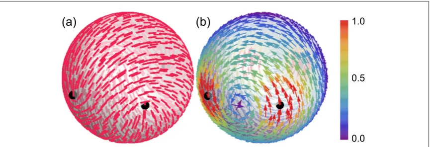
Figure1gives an example of the director for four+1/2 defects in a planar configuration and the
corresponding activeflow given by equation(3), which is seen to consist of two large counterrotating vortices and two pairs of smaller vortices and stagnation points. This emergence of stable vortices is the germane feature of the activeflows on spherical shells.
The director dynamics is dominated by the motion of defects, when the orientational dynamics is rapid[28]. In our approach the director is instantaneously given by the parametrisation(1)as the defect positions change. The defects are advected by theflow they create and we describe their motion in a point-particle description [30,40,41]. Each defect moves due to the tangential component of the activeflows, given by equation(3), and due to a net forceFkwith which all other defects act upon it according to standard nematic elasticity[38]. This force, as given in equation(35)–(37)in appendixB, provides elastic attraction or repulsion of defects depending on their topological strength, with an effective friction coefficientξand elastic constantK[28,42]. The
overdamped dynamical system for the defect positionsrk( )t is
r
v F
t
t t t k n
d d
1
, 1, .., . 5
k
k k def
x
= + =
( )
( ) ( ) ( )
The resultant dynamics is similar to[28], except that here we obtain the advectiveflowvkfrom a self-consistent
hydrodynamics in the spherical shell and generalise to an arbitrary collection of defects. Within the thinfilm approximation theflow diverges in magnitude at the defects, therefore we introduce a short-length cut-off and obtain the velocity of a defect located at(q fk, k)as an average of theflow over a small circlegk( )s centred at the
defect
v t 1 u s t s
2 , d . 6
k
k p =
g ^
∮
( ) ( ) ( )
For the defect motion theflow is evaluated at the outer surface, where f r(˜=1)= -1 2. The circle s cos s , sins sin ,s 0, 2
k k k k
g ( )=(q +r ( ) f +r ( ) ( ))q Î[ p], has the opening angleρ, which is the dimension-less cut-off length. Since this is where the continuum, thinfilm description breaks down, it can be associated with either thefilm thickness or the defect core radiusrcthrough
R h r
1
max 0, c . 7
r= { } ( )
[image:4.595.121.554.61.209.2]The core size could be measured for a particular experimental system, for instance as the size of the region around a defect which is devoid of active nematogens, and may depend on other system parameters.
With the time scale of elastic relaxationt =xR K2 we definet˜=t tand equation(5)takes the form
t Rv RF , 8
k
k, k,
q t t
x 
¶˜ = q+ q ( )
v F . 9
t R k R k
1
sin , ,
k
k
= +
f q
t
f xt f 
¶˜
(
)
( )This choice of time scale sets the scale of the elastic terms toK˜ =tK xR2=1. This identifies the scaling of
vk R
t∣ ∣ as the defining parameter for the defect dynamics, which represents the ratio of active to elastic effects and depends on the topological strength of the defect through∣vk∣. Equations(8)and(9)are integrated
numerically for different defect configurations using a standard Runge–Kutta method.
3. Results
3.1. Activeflow at the defects
In addition to the singularities in the director, the vortices infigure1(b)contain singularities in theflowfield, about which theflow circulates. Suchflow singularities are topologically required[29]and can be generated at the locations of defects in the director. A general relationship between defects andflow singularities follows from evaluating(3)on the small circlegk( )s and expanding in powers ofρ, the angular distance to thekth defect(see appendixA). We make use of the stereographic projection to write
ur u iu mkei 2mk 1sei2 1 mk ke i2w zk 1 , 10
r
= q+ f= - - f - +
˜( ) ˜ ˜ ( ) ( ) ( ) ( ) ( )
wherew z( )k =a0+mkp+ åj k¹ mjIm ln( (zk-zj)). The dominant contribution to theflowu˜^near thekth defect diverges as~1 rand has the winding number
m
2 k 1. 11
= - ( )
Unit strength defects produce a vortex(=1)in theflow. When there are two such defects, at antipodal positions, they generate two counterrotating vortices with no otherflow singularities. In fact, this is the only situation in which defect-centred vortices are the only ones present, since only for two unit strength defects the requirement2= åk(2mk-1)is satisfied. On the other hand, simple stagnation points(= -1)cannot be created at defect locations. For half-integer defects relation(11)was shown in[30,41]and theflow around a single spiral defect in active polar gels was studied in[43].
In a typical situation theflow singularities at defects are not sufficient to generate a total winding of+2. This is most evident for four half-defects, as seen infigure1(b)where allflow vortices form in between the defects, because formk=1 2theflow is non-winding(=0). Instead, it is directed along the defect’s symmetry axis,
u 1
2 e , 12
w z
1 2 i k 2 k r
= f
+
-˜ ( ( )) ( )
which is obtained as the leading order term of equation(10)evaluated for a+1/2 defect. For these defects, we approximate the advectiveflowvin(6)by this well-definedflow direction and the magnitude
v U h
rc v , 13
0 02 0 0
r
s m
~ =
∣ ∣ ≕ ( )
whereU0=h02s0 Rmis the typical activeflow magnitude in the thinfilm approach(see equation(27)in appendixA)and we replacedr=r Rc assumingrc>h0. Here, the symbol≕indicates that this expression defines the characteristic velocityv0. Ifrc<h0, then the speed becomesv0=h0 0s m. In any case, the speed of a
+1/2 defect does not depend on the shell radiusR, because it generates its own advection locally, where the defining length scales are the shell thicknessh0and, if applicable, the core sizerc. In equations(8)and(9)the
scaling of the dimensionless advective term for a+1/2 defect is
v R
h R
K rc . 14
02 0
t x s
m n
~
∣ ∣ ≕ ( )
The next term in the expansion(10), which is( )1, is non-winding only formk=1(see equation(32)in appendixA). Therefore, unit strength defects are advected with aflow∼U0, and the relevant dimensionless
parameter becomes
v R
h
K . 15
02 0 1
t x s
m n
~
∣ ∣ ≕ ( ) ( )
For all other defect types active advection scales at most as~rU0, which makes it negligible compared to the active motion of+1/2 defects. In particular,-1 2defects can be approximated withv=0in a collection of
1 2
defects.
3.2. Four+1/2 defects
In the minimal case of four+1/2 defects, the dynamics is determined by the parameterν, defined in(14). We increaseνthrough the activitys0, keeping all other parameters constant, in particular the radius, in order tofix the time scaleτ. The phasea0also affects how the defects move. In the ranges(0,p 4)and(p 4,p 2)the dynamics is similar and we choosea0=p 2-0.2for the examples in the plots. The marginal cases are discussed at the end of this section.
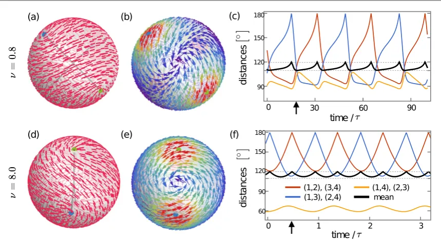
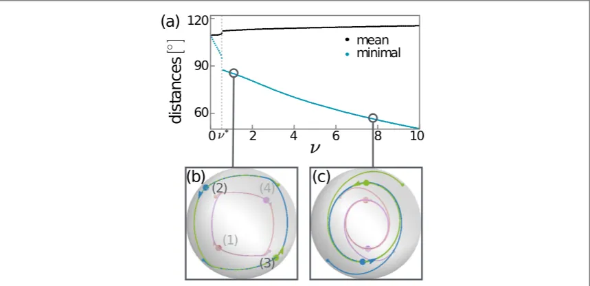
For intermediate activity the positions of the four defects periodically pass through tetrahedral and planar configurations, as shown infigures2(a)–(c), which is the dynamics found in experiments[28]. The motion is characterised by the formation of two counterrotatingflow vortices that separate the defects into two pairs, in which they rotate around each other. This effect becomes more pronounced as the activity is increased, as shown infigures2(d)–(f). The separation of defects within each pair decreases significantly withν. There is also a gradual change in the shape of the trajectories, from square-like to more ellipsoid, such that the tetrahedral configurations are no longer approached and the defects oscillate between two different planar arrangements. As the defects in each pair are drawn closer with increasing activity the dynamics approach the situation for two antipodal spirals in the director. In the limit, theflow consists of only one perfectly symmetricflow vortex pair. This behaviour is summarised infigure3, where the mean and the minimal angular distances are plotted against ν, the latter reflecting the decreasing separation between defects in each pair.
The total speed of the+1/2 defects, which also includes motion due to elasticity, is dominated by their active speedv0given by(13). The frequency of the defect oscillations is thus
f v R
h
r Rc , 16
0 02s0
m
~ = ( )
without accounting for the small changes in the orbit shape with increasingν. As a consequence of the radius-independent defect speed the frequency does depend on the shell size, which provides another route to tuning the defect oscillations.
[image:6.595.121.551.62.297.2]The effective hydrodynamic attraction of defects into pairs is mediated by the activeflow vortices that form in between them, which in turn are controlled by the underlying director. In the tetrahedral configuration the nematic is usually displayed as having a characteristic tennis ball texture[42,44]. However, for generic values of
Figure 2.The dynamics of four+1/2 defects is characterised by the formation of counterrotatingflow vortices and defect pairs.(a)–
0
a this texture is tilted, seefigure2(a), such that each two half-defects resemble a separated spiral defect. This enables them to approach each other in pairs.
The choicesa0=0,p 2produce no tilt in the texture of the initial tetrahedron and the resulting dynamics lack the contraction of defect trajectories in one of the directions, such that they continue passing through tetrahedra for high activity. Finally,a0=p 4does not have a dynamical regime and defects relax into increasingly tight, but stationary pairs.
In experiments, active nematic vesicles display a variety of dynamical defect states as well as shape
deformations[28]. For intermediate vesicle sizes of about 20μm the active nematic layer is reported to form four half-integer defects, which move on periodic trajectories similar to those predicted by our model for
intermediate values ofν, such as the trajectories infigure3(b). The time evolution of the mean angular distance infigures3(c),(f)is also in good agreement with experimentally measured values. It would be interesting to see how this dynamics changes when the vesicle radius is increased. Other structures which are observed instead of four half-defects include an equatorial ring, which occurs in smaller vesicles, and a spindle-like structure that forms from microtubules with higher rigidity. Both are reminiscent of a director with two+1 defects, which we consider in section3.4.
3.3. Linear stability of static configuration
The defects only move above a criticaln*»0.7(figure3)and we describe this transition in a linear stability analysis. The system is initialised with the four defects at the vertices of a tetrahedron with
, , ,
i0
q( )=(b p-b b p -b)andfi( )0 =(0,p 2, , 3p p 2), withb =arctan( 2). It is evident from simulations that for activities below the threshold the defects settle into an increasingly distorted tetrahedron, which can be described by the coordinates
, 17
1 3 10
* *
q =q =q( )-dq ( )
, 18
2 4 20
* *
q =q =q( )+dq ( )
, , 19
1 1 0
2 2 0
* *
f =f( )-df f =f( )+df ( )
, , 20
3 3 0
4 4 0
* *
f =f( )-df f =f( )+df ( )
with small deviationsdqanddfas shown infigure4(a). Using this ansatz wefind analytical solutions for the two deviations at linear order. The deformation of the tetrahedron is a superposition of two modes—twisting around and stretching along thez-axis, illustrated in the inset offigure4(a).
[image:7.595.123.553.62.270.2]In order to study the linear stability of the skewed tetrahedron that the four defects settle into for low activity we write their dynamical equations as
x
g x t
t t
d
d = , 21
( )
( ( )) ( )
wherex( )t =( ( )q1 t ,¼,q4( )t ,f1( )t ,¼,f4( ))t Î8is the vector of spherical defect coordinates andg x( ( ))t are the concatenated right-hand sides of equations(38)and(39)in appendixB. We use the ansatz given by(17)–
(20)for thefixed pointx*representing the skewed tetrahedron, with0<dq df, 1. Linearised indqanddf, the stationary conditiong x( (dq df, ))=0has the solutions
, 2 cos 2 2
2 sin 2 3 2 cos 2 3 , 22
0 2 2 0
0 0 2
dq n a n p a n
n a p n a p
= - +
+ +
( ) ( ( ) )
( ) ( ) ( )
, 2 3 3 2 2 cos 2
12 sin 2 9 csc sec 2 cos 2 , 23
0 2 0
0 0 0 0
df n a n p n a
n a p a a n a p
=
-+ +
( ) ( ( ))
( ) ( ) ( )( ( ) ) ( )
which are plotted infigure4(a)together with the deviations measured in the simulations.
At a critical activity the skewed tetrahedron becomes linearly unstable. A perturbationdxaway from x*=(q1*,¼,f*4)evolves according to
x
g x
t d
d x* , 24
d = d
∣ · ( )
and the spectrum of the dynamical matrixg∣x*characterises the linear stability ofx*. The spectrum is plotted infigure4(b), calculated numerically from measured deviations and from the approximate solutions(22)and
(23), respectively. The simulation data suggests that one eigenvalue changes sign atn*, while all others stay non-positive, indicating that the skewed tetrahedron is stable belown*. The three vanishing eigenvalues correspond to rigid body rotations. Calculating the eigensystem using the analytical solutions for the deviations above the threshold allows to identify the mode that becomes unstable, albeit with an overestimated critical activity. The eigenvaluel7becomes positive atn »1.0, which marks the linear instability of the skewed tetrahedron towards a deformation that strongly increases the twist and slightly reverses the stretching. This can be seen from the corresponding eigenvector, which is of the form(a,-a a, ,- -a, b b, ,-b b, )withba>0, and this is exactly the dynamics found in simulations at the beginning of the periodic orbits(seefigures3(b)and(c)).
3.4. Two+1 defects
ALCs can develop unit strength defects in their orientation[43,45]and the confinement to a spherical shell provides a setup where two such defects could be topologically stabilised. We study the advection of two+1 defects in the limit of very strong activity, settingK˜ =0and using the active time scaleT R2 h
02 0
m s
= . The
value ofa0that is required to generate a particular director geometry at the defects depends on their position. This ambiguity can be removed by settinga0= -arg(z1-z2)+a˜0, where the additional constant is found by imposing an aster-geometry fora˜0=0for both defects irrespective of their position. Now,a˜0Î[0,p 2] produces increasingly tilted spirals, up to two pure vortex defects fora˜0=p 2.
When the two+1 defects are antipodal there is no advection and theflow again consists of two counterrotating vortices, which coincides with four half-defects in the limit of high activity. If the angular distance of the two+1 defects is<p, wefind that they are either attracted to or repelled from each other by active advection, depending on the local director geometry, as shown infigure5(a). Two defects that are aster-like
(0a˜0<p 4)experience active hydrodynamic repulsion and relax into an antipodal configuration. Vortex-Figure 4.(a)Deviations of defect positions from the tetrahedron in the small activity regime. Shown are deviationsdqanddf measured in simulations(circles)and obtained from an analytical solution for the stationary configuration at linear order(lines).Inset: the corresponding twist(red arrows)and stretching(blue arrows)modes of deformation of the initial tetrahedron.(b)Spectrum of
g
[image:8.595.121.553.63.187.2]like defects(p 4 <a˜0p 2)show the converse effect and are drawn towards each other. In this idealised setting without elasticity, they would merge into a+2 boojum, with a localflow structure of a+3 singularity accompanied by a stagnation point at the antipodal point. Two perfect spiral defects(a˜0=p 4)keep a constant distance, rotating around each other on a circular path.
During this motion the defects are typically spiralling inward or outward, as shown infigure5(b). Only in the two limiting cases do the defects move along their connecting geodesic. Figure5(c)shows the activeflow with the additional vortex in between the defects(a˜0=5p 16), that draws the defects inward on a spiralling trajectory. The defects’trajectory rotates in a direction opposite to the rotation of their localflow vortices.
When elastic repulsion is included, withK˜ =1, the defects relax into the antipodal configuration for alla˜0 for activities up ton( )1 »12. Above this threshold active attraction overbalances the elastic repulsion for large enougha˜0, as shown infigure5(d). Interestingly, in such cases the defects again collapse into a very tight pair rather than equilibrating at somefinite distance. In an experimental system,fluctuations in the tilt of a spiral around the limiting value ofa˜0might therefore lead to oscillations between the antipodal and the collapsed configurations.
3.5. Many-defect states
When the activity∣ ∣s0or the shell sizeRare increased additional1 2defect pairs may be created on top of the four+1/2 defects, as the system approaches the onset of active turbulence[24]. To study such situations we increase the radius asR=gR0, withg>1, keeping all other parametersfixed. This changes the elastic time
scale to 2
0
t=g t and the activity-to-elasticity ratio ton=gn0. The reference values correspond to parameters in section3. A for the regime of tetrahedral-planar oscillations withn0=1.
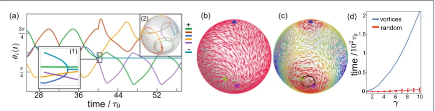
[image:9.595.121.555.63.184.2]We consider a system with four defects in this oscillatory state and inject one1 2pair at a random position. Figure6(a)shows how the dynamics react to this perturbation. One of the+1/2 defects very quickly annihilates with the-1 2and the remaining four defects resume the oscillation, usually in a different pairing. Similarly, when all defects are placed at random positions the annihilation events happen rapidly, leaving the
Figure 5.Active advection leads to repulsion of two aster-like defects and attraction of two vortex-like defects on a sphere.(a)Distance of the two+1 defects over time for different local director geometry, controlled bya˜0, which varies in steps ofp 16. Here, the motion of defects is due to active advection only, withK˜ =0.(b)Perfect asters(a˜0=0)or vortex defects(a˜0=p 2)move along geodesics, but in general the defects move on outward or inward spiralling trajectories. Two perfect spirals(a˜0=p 4)move along a circular path, without changing their distance.(c)Two spiral-like defects(a˜0=5p 16)are attracted to each other by theflow vortex that forms in between them; their inward spiralling trajectories are shown in black.(d)When elasticity is included, attraction of+1 defects is found only forn( )1above a threshold and for large enough tilt
0
a˜ .
Figure 6.(a)Four+1/2 defects show regular oscillations before and shortly after the insertion of an additional1 2defect pair, as seen fromqi( )t fori=1,¼, 6withg=2.Inset 1:close-up on the rapid annihilation of the additional pair.Inset 2:defects resume
[image:9.595.120.554.284.395.2]is transient and reduces to the four-defect state due to coalescence of oppositely charged defects. Infigure6(d) the times to thefirst annihilation event for this metastable configuration and fornpair=2with random initial defect positions are compared. For the vortex configuration this time increases considerably withγ. This opens an interesting direction of tuning specific many-defect states before the onset of active turbulence by exploiting the topologically required singularities in bothflow and director. The metastability of such configurations could be aided by an advantageous manipulation of the shell shape, for instance by trapping positive defects in regions of higher curvature[46].
4. Discussion
Our results can be extended to contractile activefluids by changing the sign of the activitys0. The reversed sign of theflow exchanges the role of splay-like and bend-like distortions in the orientation. The direction of motion of half-integer defects is reversed, but the tetrahedral-planar oscillations and the formation of vortices—with opposite rotation sense—is unchanged. Similarly, the type of active interaction between+1 defects is reversed. The thinfilm approach used here allows for a non-zero radialflow component, which in general is present in the examples considered and enables the repulsion or attraction of defects due to activeflows. The radial component is small,~(h0 R), compared to tangentialflows and will result in a dynamic deviation from the spherical shape that complements the defect motion. Stationary shell shapes, e.g. for two asters, should locally resemble profiles found forflat droplets of active nematics with defects[36,37]. We have taken a one elastic constant approximation and isotropic viscosity for simplicity, but in systems of elongatedfilaments one can expect anisotropy. In particular, longflexible nematogens are much more compliant to bend distortions than to splay [47]. If anisotropy is sufficiently large it could lead to qualitative changes of the dynamics, which is certainly an
extension worth pursuing.
Our approach provides a closed form solution for the activefluidflow in an active nematic shell within the thinfilm approximation, thus allowing to study the advection of defects with arbitrary topological strengths in an efficient, particle-like dynamics. The simplified representation of the director and its time evolution enables us to make theoretical predictions for certain aspects of this dynamics, such as defect velocities, the onset of the dynamical regime, and dependence on shell radius. However, to explore the full range of possible dynamics of active nematic shells numerical solutions of nemato-hydrodynamic equations might be better suited, such as the recent numerical study of half-defect dynamics for a wider range of activities including the transition to an active turbulent regime[48]. Other interesting directions, which would be relevant for a comparison with experiments, include deviations from the spherical shape and variation of elastic constants.
Our work establishes the formation of vortices under confinement as a generic feature also for ALCs on spherical surfaces. It would be interesting to extend to other topologies, for instance tori with additional handles[49].
Acknowledgments
We thank Carl Whitfield, Daniel Pearce and Julia Yeomans for enlightening discussions on various aspects of this work. This work was supported by the UK EPSRC through Grant No. A.MACX.0002.
Appendix A. Flow in a thin active nematic shell
r r R 1 1 , e = ⎜⎛ - ⎟ ⎝ ⎞⎠ ˜
and the corresponding partial derivatives rf h1 rf 0
¶ = ¶˜ , for some functionf(r). In the dimensionless form, for
instance theθ-component of the Stokes equation becomes
R U p
R
U u
0 a , 25
r
2
0
2 2
0
2 2
s
e m
e
m e
= - ¶ +q (· )q+ ¶˜˜q+ ( ) ( )
and there is a similar expression for thef-component. The divergence of the active stress is
R
1
sin 2 cos
cos 2 cos
. 26
a 0 cos 2
sin sin 2 sin
s s y y q y
y y q y
= - - ¶ + + 
¶ + + 
q qy f
q qy f
⎛ ⎝ ⎜ ⎜ ⎜ ⎞ ⎠ ⎟ ⎟ ⎟ · ( ) ( ) ( ) ( ) ( ) ( ) ( )
Therefore, in order for the activity to drive the tangentialflows the corresponding prefactor in(25)has to scale as 1
( ), leading to the dimensionless prefactor
R U 27 0 2 0 0 s e m s = ˜ ( )
and a similar relation for the pressure. Analogous to planar thinfilms[33,36,37], the leading order part of ther -component of the Stokes equation yields a constant pressure. With the boundary conditions
u 0 and u 0, 28
rs rs 1 rs 0
¶˜ ˜ ∣f˜= = ˜ ∣f˜= = ( )
the solution(3)for the tangentialflow components is obtained.
For afixedr˜, for instancer˜=1used for the defect dynamics, the tangentialflow can be written in a complex representation making use of the stereographic projectionz(q f, )=Rcot(q 2 e) if. In this way, the projection
point is the north pole and the plane crosses the sphere along the equator. The complexflow is given by
u z z u u z
R z z R z z R m z z z z , i
2e 2 . 29
z z j n j j j
0 i2 , 2
1 2 def
å
s = + = - - +-q f - a
= ⎪ ⎪ ⎪ ⎪ ⎧ ⎨ ⎩ ⎛ ⎝ ⎜ ⎞⎠⎟ ⎫⎬ ⎭ ˜( ¯) ˜ ˜ ˜ ∣ ∣ ∣ ∣ ∣ ∣ ∣ ∣ ( ) ( ¯)
This expression is well-defined through the stereographic projection of the tangentialflow onto the plane, which is given in the complex form asu=ux +iuyand relates tou˜as
u˜= -(1-cosq)eifu¯, (30)
whereu¯denotes the complex conjugate ofu. We evaluate(29)on the projection of the small circlegk( )s introduced in the main text, which has the form
z s z R
1 cos e 31
k k s i k r q =
-- f
-( ) ( ) ( )
withsÎ[0, 2p], provided the circle does not enclose one of the poles on the sphere. An expansion of(29)in powers ofρreads
u m
m
h z z h z z
e e e
e e
2 e e , ,... e , ,... , 32
k m s m w z
w z m k m s m s
i 2 1 i2 1 i2
i2 i2 i2 1 i2
1 1 1 i2 2 1 1
k k k k
k k k k k k
r r r = + + + f f f - - -- -
{
-}
˜( ) ( ¯ ) ( ¯ ) ( ) ( ) ( ) ( ) ( ) ( ) ( )where the functionsh1andh2only depend on the defect positions and other constants. Integrating this
expression oversyields a non-winding contribution at the order(1 r)formk=1 2and at the order( )1 for
mk=1, as discussed in the main text.
Appendix B. Point-particle-like dynamics of defects
The free energy of a nematic on a sphere can be phrased in terms of the defects’pairwise interaction energies and their self-energies[39,42,44], which are constant in our model,
E K m m
2 i j ln 1 cos const. 33
i j n
i j ij
E K m m
1 cos 36
k j j k
j
kj
1,
k p
å
b ¶ = -q = ¹ ( )
and the expression for¶fkEis analogous. The elastic terms in the dimensionless dynamical equations(8)and(9) can be written as
RF
K
R m m
cos
1 cos , 37
k
k j j k
n j kj kj 2 1, k def
å
t x t x p b b = - ¶ -q q = ¹ ( ) ( )and a similar expression for thef-component. Making time dimensionless withτleads toK˜ =tK xR2=1. For example, for four+1/2 defects the full dynamical system reads
w z 4
cos
1 cos 4cos 2 , 38
t k
j j k
kj kj k k 1, 4 k
å
q p b
b n f ¶ = - ¶ - - -q = ¹ ( ( )) ( ) ˜ w z 1
sin 4 sin
cos
1 cos 4sin 2 39
t k
k k j j k
kj kj k k 1, 4 k
å
f q p q b b n f ¶ = - ¶ - - -f = ¹ ⎛ ⎝ ⎜⎜ ( ( ))⎞⎠⎟⎟ ( ) ˜fork=1,..., 4, wherew zk =a0+ 2 + å12 j kIm ln zk-zj p
¹
( ) { ( )}andνis defined in equation(14)in the
main text.
For all defect configurations the dynamical systems are integrated using the ordinary differential equation solverode23sprovided by the softwareMATLAB 2016a, with relative and absolute accuracies set to10-6t.
ORCID iDs
Diana Khoromskaia https://orcid.org/0000-0003-2597-6336
References
[1]Prost J, Jülicher F and Joanny J F 2015Nat. Phys.11111
[2]Marchetti M C, Joanny J F, Ramaswamy S, Liverpool T B, Prost J, Rao M and Simha R A 2013Rev. Mod. Phys.851143
[3]Ramaswamy S 2010Annu. Rev. Condens. Matter Phys.1323
[4]Kruse K, Joanny J F, Jülicher F and Prost J 2006Phys. Biol.3130
[5]Tjhung E, Tiribocchi A, Marenduzzo D and Cates M E 2015Nat. Commun.65420
[6]Tjhung E, Marenduzzo D and Cates M E 2012Proc. Natl Acad. Sci. USA10912381
[7]Salbreux G, Prost J and Joanny J F 2009Phys. Rev. Lett.103058102
[8]Turlier H, Audoly B, Prost J and Joanny J F 2014Biophys. J.106114
[9]Brugués J and Needleman D 2014Proc. Natl Acad. Sci. USA11118496
[10]Salbreux G, Joanny J F, Prost J and Pullarkat P 2007Phys. Biol.4268
[11]Callan-Jones A C, Ruprecht V, Wieser S, Heisenberg C P and Voituriez R 2016Phys. Rev. Lett.116028102
[12]Doostmohammadi A, Thampi S P and Yeomans J M 2016Phys. Rev. Lett.117048102
[13]Wioland H, Woodhouse F G, Dunkel J, Kessler J O and Goldstein R E 2013Phys. Rev. Lett.110268102
[14]Wioland H, Woodhouse F G, Dunkel J and Goldstein R E 2016Nat. Phys.12341
[15]Guillamat P, Ignés-Mullol J and Sagués F 2017 Control of active nematics with passive liquid crystalsMol. Cryst. Liq. Cryst.646226–34
[16]Woodhouse F G and Goldstein R E 2012Phys. Rev. Lett.109168105
[17]Segerer F J, Thüroff F, Piera Alberola A, Frey E and Rädler J O 2015Phys. Rev. Lett.114228102
[18]Mohammad Nejad T, Iannaccone S, Rutherford W, Iannaccone P M and Foster C D 2014Biomech. Model. Mechanobiol.14107
[19]Whitfield C A, Marenduzzo D, Voituriez R and Hawkins R J 2014Eur. Phys. J.E378
[20]Kumar A, Maitra A, Sumit M, Ramaswamy S and Shivashankar G V 2014Sci. Rep.43781
[21]Simha A R and Ramaswamy S 2002Phys. Rev. Lett.89058101
[22]Sanchez T, Chen D T N, DeCamp S J, Heymann M and Dogic Z 2013Nature491431–4
[23]Dunkel J, Heidenreich S, Drescher K, Wensink H H, Bär M and Goldstein R E 2013Phys. Rev. Lett.110228102
[24]Giomi L 2015Phys. Rev.X5031003
[25]Adamer M F, Thampi S P, Yeomans J M and Doostmohammadi A 2016Nat. Commun.710557
[26]Schaller V, Weber C, Semmrich C, Frey E and Bausch A R 2010Nature46773
[27]Sumino Y, Nagai K H, Shitaka Y, Tanaka D, Yoshikawa K, Chaté H and Oiwa K 2012Nature483448
[29]Hopf H 1989Differential Geometry in the Large(Berlin: Springer)
[30]Giomi L, Bowick M J, Mishra P, Sknepnek R and Marchetti C M 2014Phil. Trans. R. Soc.A37220130365
[31]Sknepnek R and Henkes S 2015Phys. Rev.E91022306
[32]Green R, Toner J and Vitelli V 2016(arXiv:1602.00561)
[33]Oron A, Davis S H and Bankoff S G 1997Rev. Mod. Phys.69931
[34]Takagi D and Huppert H E 2010J. Fluid Mech.647221
[35]Sankararaman S and Ramaswamy S 2009Phys. Rev. Lett.102118107
[36]Joanny J F and Ramaswamy S 2012J. Fluid Mech.70546
[37]Khoromskaia D and Alexander G P 2015Phys. Rev.E92062311
[38]Chaikin P M and Lubensky T C 1995Principles of Condensed Matter Physics(Cambridge: Cambridge University Press)
[39]Lubensky T C and Prost J 1992J. Phys.II2371
[40]Denniston C 1996Phys. Rev.B546272–5
[41]Pismen L M 2013Phys. Rev.E88050502
[42]Vitelli V and Nelson D R 2006Phys. Rev.E74021711
[43]Kruse K, Joanny J F, Jülicher F, Prost J and Sekimoto K 2004Phys. Rev. Lett.92078101
[44]Nelson D R 2002Nano Lett.21125–9
[45]Nedelec F J, Surrey T, Maggs A C and Leibler S 1997Nature389305
[46]Selinger R L B, Konya A, Travesset A and Selinger J V 2011J .Phys. Chem.B11513989–93
[47]De Gennes P-G 1976Mol. Cryst. Liq. Cryst.34177–82
[48]Zhang R, Zhou Y, Rahimi M and de Pablo J J 2016Nat. Commun.71–9