University of Southampton Research Repository
ePrints Soton
Copyright © and Moral Rights for this thesis are retained by the author and/or other copyright owners. A copy can be downloaded for personal non-commercial
research or study, without prior permission or charge. This thesis cannot be
reproduced or quoted extensively from without first obtaining permission in writing from the copyright holder/s. The content must not be changed in any way or sold commercially in any format or medium without the formal permission of the
copyright holders.
When referring to this work, full bibliographic details including the author, title, awarding institution and date of the thesis must be given e.g.
AUTHOR (year of submission) "Full thesis title", University of Southampton, name of the University School or Department, PhD Thesis, pagination
Sublimation from Barium Oxide Coated Cathodes.
Thesis presented for the degree of Doctor of Philosophy at the
University of Southampton
Kevin Ross, B'eSc., G-rad, Inst. P.
CONTENTS
Introduction
page
Chapter I General properties of the oxide cathode
1.1 Introduction 1
1 . 2 Preparation of the oxide cathode 2
1.3 Activation 7
1.4 The activated state 10
1.5 The physical structure of the oxide
cathode 11
1.6 The cathode g,nd its environment 13 1.7 Preconversion of the oxide cathode 14
Chapter II The mechanism of the oxide cathode
2.1 Early emission theories 16
2.2 The band structure of solids;
semi-conductor theory 19
2.3 The contact potential difference 24
2.4 Thermionic emission 25
2.5 Voltage characteristics 30
2.6 Electrical conductivity 31
2.7 Current dependant processes 38
2.8 Thermal stability and evaporated
products 43
2.9 Emission decay effects 48
3.1 Introduction 52
3.2 Sublimation 52
3 . 3 Condensation 53
3.4 Chemical and physical adsorption 57 3.5 Modification of the adsorbent work function
by adsorbates 58
3.6 Work function variations of metals coated
with barium oxide films 63
3.7 Sublimation activation energy
measurements for barium oxide on platinum 67 3.8 Estimation of film thickness 69
Chapter IV The measurement of work function
4.1 Introduction 71
4 . 2 The Richardson line method 72
4.3 The effective work function 74
4.4 Anode work functions by displacement of
retarding potential characteristic 76 4.5 Measurement of contact potential
difference by the intersection method 80
4.6 The Kelvin technique 82
Chapter V The apparatus and techniques
5.1 Introduction 86
5'.2 The vacuum systems 86
2, The Venema and Bandringa ultra-high
vacuum system 91
5.3 The experimental tu.be 93
5.4 The construction of an experimental tube 95
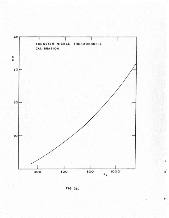
5 . 5 Temperature measurements 97
5 . 6 Emission measurements 99
5 . 7 Kelvin measurements 100
Cliapter VI The preliminary results
6.1 Introduction 104
6^2 The N series of tubes 105
6 . 3 The K series of tubes 108
6 . 4 The M series of tubes 110
6 . 5 The T series of tubes 112
6.6 The vacuum systems 114
6 . 7 Experimental error 116
6 . 8 Conclusions from the preliminary results 118
Chapter VII Results (i)
7 . 1 Introduction 120
7.2 Electron temperatures 120
7 . 3 Sublimation curves for cathode activation
states II to VII 121
7 . 4 Anomolous sublimation curves 124
T\5 The .anode:; temperature during activation
and sublimation 124
7 . 8 7 . 9
7.10
7.11
T.12
film bombardment Negative ion current
Effect of varying the anode potential during sublimation
Conductivity of the anode film Activation energy of barium oxide Estimation of a monolayer
Chapter "VIII Results (ii)
&.1
8.2
8 . 3
Introduction
Anode binding energies The 100 volt effect
126 128 129 130 131 131 138 139 143 Chapter IX 9^1 9\2 Appendix I
Discussion of results
Suggestions for future work
145
162
References
Some work function measurements in experimental tubes containing uranium and zirconium
carbides, and niobium 166
176
INTRODUCTION
It has been known for many years that low work function anodes are frequently associated with efficient thermionic emitters. One of the best thermionic emitters, the oxide cathode, always contaminates the anode to such an extent that sometimes its work function (which may originally have been that of clean nickel, molybdenum, or tungsten) appears to be lower than that of the oxide cathode. During the lifetime of such a cathode, the anode surface becomes sufficiently contaminated by sublimed materials from the cathode for its work function to have fallen by several electron volts.
The present work was initially undertaken to investigate the work function changes that take place at the anode of a diode containing a barium oxide cathode, during the course of decomposition and activation of the cathode. Andde work functions have been measured by three independent methods: the Richardson line, the displacement of retarding potential characteristic, and the Zisman modification of the Kelvin technique. Most of the measurements were made at indicated
-9
pressures of better than 10 ramHg.
tungsten substrate* A two phase model is proposed for the adsorption of barium oxide on tungsten at room temperature, and evidence is also presented for the existance of a third activated binding state.
Some measurements, reported in the appendices, have also been made on the work functions of uranium and zirconium
CHAPTBB I.
GENERAL PROPERTIES OF THE OXIDE COATED CATHODE
1.1. Introduction-^
The discovery of the oxide coated cathode as an important thermionic emitter of electrons is due to Wehnelt(1904). In the course of experiments on gas discharges, he observed the emission of cathode rays from some areas of a platinum filament at relatively low temperatures and low anode voltages. At these low temperatures the emission could not have been
directly from the platinum, but might have been the result of some impurity on the platinum surface. Wehnelt thought these impurities might be metal oxides originating from the stop-cock grease of the vacuum system. Systematic examination of the electron emission from various metal oxides showed that the most copious emitters of electrons were the alkaline earth oxide?. This accidental discovery subsequently led to the modern oxide cathode which remains the most important of
thermionic emitters.
conditions, especially those of vacuum. Improved vacuum techniques resulting from the introduction of diffusion pumps and liquid air traps and helped to eliminate many of the
experimental difficulties. Later, with the arrival of Wilson's theory of semi-conductors many of the observations on oxide
cathodes could be correlated under a coherent, though still inadequate theory.
As a result of recent research which will be described in detail below, and still further improved vacuum techniques which enable pressures of 10"^^ irmHg. to be attained, a more
satisfactory model of the oxide cathode is emerging.
In spite of the tremendous inroads made by transistors on the use of thermionic valves, the great reliability and long life of electron tubes containing oxide coated cathodes
continues to makes their study of prime technological importance.
1.2. Preparation of the oxide cathode.
The term oxide coated cathode can embrace a variety of
3.
a maximum of 10~^cm. ' Cathodes generally operate at a temperature of about 1100°K, and can be heated either
indirectly, in which case the base is in the form of a tube or box, or directly by depositing the coating on a wire or metal strip.
The demands made on the base metal are many and only a few metals and alloys are suitable. such materials must have low vapour pressures at the normal operating temperature of the cathode, and melting points well above this temperature, be chemically inert towards the oxide and any gases or vapours associated with it, be readily outgassed during the processing of the cathode, and have adequate mechanical, strength at high tei#erature8.
For directly heated cathodes, tungsten is preferred as a base material, although it has a disadvantage that at high temperatures a chemical reaction takes place with the alkaline earths to form a high resistance layer. When current is
A third metal commonly used as a base material is nickel. In the pure state this is like platinum, chemically stable and has no effect on the emission. To Improve the low
tensile strength of pure nickel an alloy known as '0' nickel has been developed having the approximate
compositions-Co 0.5% Fe O.Sgg Si 8.1% C 0.4% Mn 0.15% Mg 0.1% Cu 0.1% S 0.005%
The impurity agents present in '0' nickel, besides resulting in a stronger cathode base, have been found to enhance the emitting prope-rties of the cathode. At the same time silicon and manganese produce high resistance interface layers thus tending to shorten the life of the cathode.
Care is necessary in cleaning the base material before application of the coating of oxide. Washing the base in an organic solvent removes any grease present; oxides that might exist on the surface can usually be reduced by furnacing in dry hydrogen at 1300®K.
Emission measurements on the pure oxides of barium, strontium, and calcium at the same temperature give current densities approximately in the ratio lOOilOil. A mechanical mixture of any of these oxides has an emission current density
5.
higher emission current density than the mechanical mixtureo Mixed crystals of harima/atrontima oxide, (BaSrr)©, have good emission properties, but by adding calcium to form (BaSiCa)O so that the crystals have a composition BaO;SrO:.GaO of 49:44s7, the emission is optimised.
The alkaline earth oxides are unstable in air being rapidly converted into the hydrate and carbonate by water
vapour and carbon dioxide. The formation of these compounds, which is accompanied by a change in volume, effects the
bonding between base and coating, usually resulting in the coating flaking away from the base. For this reason the oxide is now generally prepared in vacuum, the alkaline earth being applied to the base as a carbonate and decomposed to oxide by pyrolysis in vacuum.
The carbonate can be prepared as a white precipitate by the addition of ammonia to a solution of the pure alkaline earth nitrate. The size of the precipitated particles depends on the temperature of the nitrate solution, and its concentration. After drying, the precipitate is mixed with an organic binder dissolved in a volatile solvent and ball-milled for several hours. Nitrocellulose is commonly used
The carbonate may be applied to the base by one of three
methods; spraying, painting, or electrophoresis. Mien painting is used, successively thin layers of carbonate are
super-posed until the required coating thickness is reached* This method, which is sometimes used for directly heated cathodes, does not normally lead to a uniform coating.
Indirectly heated cathodes are generally coated by spraying the carbonate suspension onto the base. The physical
properties, particularly density, of the carbonate deposit, vary widely in this process; gas pressure during the spraying, the ambient temperature, the distance of the spray gun from the base, and the concentration of the carbonate solution can all effect the final result. In general, surfaces prepared by spraying tend to be very porous. Application by electro-proresis is preferred where careful control of the coating
thickness and a less porous structure are desired.
When sealed into an envelope and mounted on the vacuum system, the carbonate is converted to oxide by raising the
o
temperature of the cathode to 1300 K over a period of about 50 seconds. The gases evolved from the cathode during this process are pumped away as fast as possible* Decomposition of the carbonate can be judged con^lete when the pressure in
—6
7.
o-and on the valve components: this absorbed gas can only be removed from the system by a rigorous outgassing programme
involving baking at 450°c together with eddy current heating of metallic components
1.5. Activation.
After decomposition of the carbonate the emission
obtainable from the cathode is usually low. Added to this there are wide variations in the emission characteristics from cathode to cathode. A higher and more stable emission can be obtained by processes called activation* The net effect of activation (which will be discussed in chapter II) is thought to be to produce an excess of free barium in the oxide. Oxide cathodes can be activated in any one, or a combination of at least five distinct methods*
(l) Theiraal activation.
Heating the cathode momentarily to a temperature (1350°K) well above its normal operating temperature can produce an excess of alkaline earth metal by increasing the rate of
chemical reaction between the oxide and reducing agents; these can arise from two sources: (1) carbon and carbon dioxide
reducing impurities that may be present in the base material. To investigate the possibility of reduction by carbon alone, Huber(l941) examined two types of cathode; one was prepared with a paste containing an organic binder and the other with a water paste. The presence of carbon was found to have no effect on the process of activation by reduction, though it may react with carbon dioxide to produce carbon monoxide: GOg + C ^ 200 • Carbon monoxide may also be produced by the
reaction:- 0GOg 200 + Og . The reduction of barium oxide by carbon monoxide is quite straight
foreward:-BaO + 00 Ba + COg.
After a theoretical study of the chemistry of the oxide cathode, Eittner(1953) suggests that Th, Mg, Be, Zr, U, Al, Si, should all be good activators of barium oxide, while Fe, Mo, Or, W, Mn, Ta, 0, Ti, are only moderate activators. M , Cd, Gu, Pb, Au, Pt, Rh, are relatively inert and should not produce any activation.
(2) Activation by drawing current.
By raising the cathode temperature to 1Q00®K and
applying a voltage to the anode it is possible to increase •Z
the emission current by as much as a factor of 10 . This process is generally thought to produce electrolytic
9,
given to electrolytic dissociation and associated effects in Chapter II.
(3) Activation by external reduction.
Small quantities of reducing gases such as methane also produce activation in oxide cathodes. Free barium can be produced by the reactions BaO + CH, Ba + CO + 2H
4 2
In this method the gas is introduced to the cathode at a pressure of 10"^ nu^g. and the cathode temperature then
raised to 1300°K for five or ten minutes. Hannay, MacNair and White(1949) have used this method successfully.
Hydrogen also acts as a reducing agent, but White(1949) has found that methane at 10"^ mmHg. is 100 times more effective in its reduction of barium o M d e than hydrogen even at
atmospheric pressure. However, at elevated teiaperatures methane is found to be unstable, dissociating spontaneously:
CH.-> G + 2H .
4 2
The carbon produced can deposit onto the cathode aJid thus result in a reduced emission.
Activation by external reduction is only used in experimental investigations with oxide cathodes.
(4) Activation by barium evaporation.
is not used commercially but is an expearimental tool, Beese(l9S0). Cathodes activated in this way ean be deactivated in a few minutes by raising the temperature to 1200°K thereby re-evaporating the deposited barium.
At lower temperatures the barium deposited onto the cathode surface diffuses into the bulk of the cathode matrix thus caus-ing activation.
(5) Activation by electron and ion bombardment.
Bombarding an unactivated cathode with electrons is found to have an activating effect. Electrons accumulating at the surface of the cathode lead to a change in surface potential which may give rise to an ionic current in the oxide layer and so produce activation by drawing current through the oxide. Bombardment by relatively low energy positive ions produces a similar effect.
1.4. The activated state.
Whichever of the five methods of activation are employed, the cathode emission finally reaches a steady state, although in this steady state the emission from the cathode is not uniform over the whole of the cathode area. Heinze and
l i t
stages of activation there are few emitting centres, but as activation proceeds the number of emitting patches increases to cover a large part of the cathodeo Further activation produces little alteration in tha size and distribution of
the emitting patches*
A considerable volume of work on the activation of oxide cathodes leads to the conclusion that the activated coating contains an excess of alkaline earth metal, (see for example Hermann and Wagener( 1 9 5 0 ) W a g e n e r (1954) found that the quantity of excess alkaline earth metal has an optimum value beyond which the emission does not increase. However, an
atten^t by Wooten et. al. (1955) to correlate emission with barium content failed. For an activated cathode Wooten et al.gave a
figure of 1 atom of baripn in 10® oxide molecules. The poor emission sometimes observed in cathodes with a high excess barium content indicates that other factors effect emissioDo lost important among these are probably the preparation
proceedure and the residual gas content of the final assembly*
1.5. The -physical structure of the oxide cathodeo
an important effect on the electrical performance of the cathode.
The base metal is important in determining the nature of the interface layer which results from reduction of the oxide coating by any reducing impurities diffusing out of the base metal. Reducing agents commonly used are silicon, titanium, manganese, magnesium, aluminium, and carbon. All of these react with barium oxide to form oxides, and many of the oxides in turn react with barium oxide to form higher compounds at the interface. Hooksby( 1940) (1940a) (1947) reported the formation of barium aluminate BaAl^O^, barium orthosilicate Ba„SiO , and barium orthotitanate Ba^TiO .
«o 4 2 4
Despite the fact that the interface layer gives a much stronger bond to the base metal, its growth during cathode operation often limits the life of the cathode by retarding the diffusion of reducing agents from the base into the oxide. This, together with the high resistance of the interface layer
can limit the lifetime of the cathode.
Barly investigations showed the electrical conductivity of the oxide coating to be very low compared with that of a metalo Further, all such measurements showed a general
increase in the electrical conductivity with increasing
IS.
oxide coating are now well established and thought to result from the excess alkaline earth metal in the oxide. Detailed discussion of the semi-condueting properties of the oxide cathode will be given in Chapter II» A voltage drop does
occur across this region of the cathode but it is small compared with the drop across th# interface layer*
, The exact nature of the vacuum interface is to a certain
extent open to speculation. The resistance of this region is found to be strongly influenced by dissociated ions resulting from the application of external field.
1.6. The cathode and its environment.
in dynamic equilibrium on the surface.
The effect of materials evolved from the glass envelope has been studied by Hamaker, Bruining, and Aten(l947) who found that the presence of chlorine on the cathode after activation could be accounted for by a reaction which took place during baking at 400°G:
2NaCl + 810* + H O 2HC1 +Na_8iO,.
The HCl produced then reacts with the carbonate of the cathode to form BaClg. During the pyrolysis .of the carbonate the BaOlg evaporates onto the anode. Electrons with energies greater than 10 volts are able to decompose the chloride, and the chlorine atoms produced can then find their way back to the cathode and cause poisoning.
1.7. Preconversion of the oxide cathode.
Many effects resulting from the liberation of large
quantities of gas during decomposition of an oxide cathode can be eliminated by 'preconverting' the cathode. To do this the cathode is mounted in a seperate envelope, evacuated, and
15.
allows the conversion of the oxide into the hydroxide only. Formation of the hydrate which occurs at lower temperatures, leads to a change in volume and hence to cracking and flaking of the coating. Heating also prevents the carbonate refonning from carbon dioxide present in the air. Preconverted cathodes have been observed by Haas and Jensen(l959) to give better
CHAPTER II.
THE MECHANISM OF THE OXIDE CATHODE
2ol» Early emission
theories-The introduction of a satisfactory semi-conductor theory in 1931 led to an important advance in understanding the
mechanism of the oxide cathode. By this time a theory accounting for the thermionic emission from pure metals had been established, the temperature dependance of emission being represented by Richardson's equation (see section 2o4.)o
The phenomena observed with oxide cathodes were not easily explained. Their high thermionic current density per watt of heater power (activity) surpassed even the more active contaminated metals such as thoriated and eaesiated tungsten, but an explanation was initially sought by analogy with these systems.
The necessity for a process of activation to produce a fully active cathode, which could be effected thermally or by drawing current through the cathode, was demonstrated by
Becker(l929). His experiments established that during either of these activation processes free metallic barium was produced, and that this resulted in the work function of the cathode
17.
The necessity for a process of activation to produce a fully active cathode, which could be effected thermally or by drawing current through the cathode, was demonstrated by Becfcer( 19Z9) • His experiments established that during either of these activation processes free metallic barium was
produced, and that this resulted in the work function of the cathode being lowered.
At the time of Bushman's review (1950), two theories existed concerning the location of the barium and hence the emitting surface of the cathode. Becker's theory (1929) held that the activity depended on a surface concentration of free metallic barium. The free barium on the barium oxide coating was considered to lower the work function in a way analogous to barium on tungsten. At the same time
Lowry(l930) considered the source of emission to be a layer of metallic barium or other alkaline earth metal on the surface of the base metal or alloyed with it. Electrons emitted from this coir^osite surface would have to diffuse through the ceating before being released into the vacuum. Apart from the source of emission, these two theories
In support of his mechanism, Dowry pointed out the pronounced influence of different base materials on the cathode performance, and also the gradual decay in activity during operation which he thought was the consequence of a slow scintering effect in the oxide. Scintering would result in a closing of the pores, thereby increasing the
resistance offered to the passage of electrons. By removing the coating completely, Becker and Sears(l931) found that the emission current dropped by three orders of magnitude.
Jones(l956) removed just the outer surface of the coating in vacuum and observed a decrease in emission by three orders of magnitude which could be subsequently restored by thermal
treatment. This indicated a marked dependence of electron emission on the external surface.
Darbyshire(1938) using electron diffraction techniques to examine surfaces of oxide cathodes, could find no positive evidence for the existance of a surface barium layer, but despite this he interpreted the results of his experiments as indicating such a layer. Other diffraction experiments by Huber and Wagener( 1942) also failed to demonstrate
con-clusively the presence of surface barium. More recent
19.
With the advent of Wilson's theory of semi-conductors (Wilson 1931), and the application of this theory to oxide cathodes, many well established experimental facts concerning the oxide cathode could be explained and some measure of
agreement was found between theoretical calculations and experiment. The theory is considered in greater detail below.
2.2. The band structure of solids; semi-conductor theory.
The behaviour of electrons in solids has been described quantitatively in terras of bands of allowed energy levels which may be seperated by gaps or forbidden energy regions. This theory can be approached by considering the discrete nature of energy levels in a free atom. When an assembly of atoms is condensed to form a crystal the energy levels of adjacent atoms interact, each discrete energy level being displaced such that a band of very closely spaced energy levels is formed. These allowed bands become wider with increasing energy and bands from different discrete levels in the individual atoms may overlap. A crystal may also have allowed energy bands which are normally unoccupied, corresponding to excited states in the isolated atoms.
•with other vacant bands or with a filled band. The occupied band immediately below the conduction bands is called the valence band.
It follows from the Pauli Exclusion Principle and as a result of the two spin quantum states of each electron, that a band of energy levels formed from N atoms contains 2N
possible electron energy states, so that when the atoms of a crystal only contribute one electron each to the valence band, the band is only half full. Electrons in such a crystal are easily accelerated by the application of low electric fields since there are levels of slightly higher energy to which the electrons caja move. When the contribution to the valence band is two electrons from each atom, all the energy levels in the band will be filled. Such solids are said to be
insulators provided the uppermest filled band does not overlap with an empty band, and the energy gap between it and the
nearest eir^ty band is about 10 eV. When this energy gap is > only about 1 eV. electrons may be excited into the conduction band at temperatures a few hundred degrees above room
temperature, and the solid is said to be an intrinsic semi-conductor. For an energy gap EgeV, the number of electrons in the conduction band is given by
21.
H = 5X10^^ exp -Sg/2kT (2.2)
When Eg is 1 eV, the ntimber of electrons in the conduction band is of the order 10^^. This is less than that of a
7 metal by a factor of 10 .
Semi-conductors usually contain impurities which can give rise to an enhanced conductivity if their concentration is sufficiently high. Such impurities can provide energy levels which lie in the forbidded region of the host crystal, and thus either supply electrons to the conduction band or accept electrons from the valence band much more readily than in the case of a pure semi-conductor.
Inqjurity levels fall into two distinct classes. Where the impurity has one or more valence electron than the host element then the in^urity energy levels are located just below the bottom of the conduction band. lonisation of these impuri ty centres by relatively low energy phonons contributes an electron to the conduction band which is then free to move in the crystal. Such impurity centres are called donors, and since the charge carriers are negatively charged, the crystal is said to be an 'n'-type semi-conduetor* When the impurity atom has one or more valence electrons less
than the host element, the impurity levels are slightly above the valence band, so that at a temperature greater than
to leave its normal state and enter the inpurity level. These iirrpurity levels are called acceptors, and conductivity takes place in the crystal as a result of electron vacancies or holes in the filled band. In this case the crystals are called 'p'-type semi-conductors.
It has been pointed out in Chapter I that considerable evidence is available for attributing the semi-conducting properties of the oxide cathode to a stoichiometric excess of
free alkaline earth metal in the crystal lattice ('n*-type semi-conduction). This excess could result from: (1) Excess alkaline earth atoms deposited either interstitially or at lattice points; in view of atomic size considerations a very distorted lattice would result from the interstitial arrange-ment* (2) The existence of vacant oxygen sites in the
lattice; this would provide an explanation for all the electronic behaviour without leading to a very distorted lattice*
Measurements using the Hall effect should make it
,1\ I N C R E A S I N G
E=E*
A E
E = E - A E
X
Q $
E = 5rEg
S E M I - C O N D U C T O R
VACUUM L E V E L
C O N D U C T I O N BAND F E R M I L E V E L
I M P U R I T Y L E V E L
VALENCE BAND
V A C U U M
F I G . I.
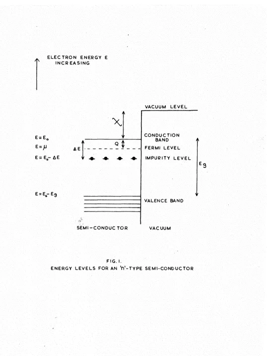
[image:31.600.9.547.49.766.2]The energy level configuration of an 'n'-type semi-conductor isdiown in Fig.l. The energy at the bottom of the conduction band is 1^, p., the electrochemical potential level is called the Fermi level of the 'n'-type semi-conductor, and represents the partial free energy of the electrons. The exact position of p between the conduction band and the
impurity levels is determined by the relative number of impurity centres, and the temperature of the crystal (see below). Eg is the energy gap between the valence band and
the conduction band.
The removal of an electron from the crystal into vacuum requires a total energy Q + x * Q is the energy necessary to raise an electron from the Fermi level into the conduction band, ©ailed the inner work function; % is the surface work function, and represents the difference in energy between the bottom of the conduction band and a position just outside the surface. The total quantity Q + X is known as the
thermionic work function 0*
24.
by Dg electrons. In addition there is a conduction band of levels above these bound states which is completely unoccupied at absolute zeroo Thermal transitions from the filled valence band to the conduction band are to be neglected on the assumption that S g » 62.
The location of the Fermi level is given by
p = Eg - AE/2 + kT/2. In. n^h^/2( 2 irm' kT) ( 2.5)
where k is the Boltzmann constant, T is the absolute
ten^erature, h is Planck's constant, and m' is the effective mass of an electron in the conduction band. For normal
densities of bound electrons the last term on the right of Eg.2.3. is of the order of magnitude kT, so that for
& E » kT
p = EQ- as/2.
The number of free electrons per unit volume in the conduction band, n^ is given by:
5 / 4 - 5 / 2
n^ = D ^ V 2 2^/^(2TTm'kT) h . exp - AE/2kT. (2.4)
If kT is large compared with 6E, all the in^urity levels will be ionised and n^ = n .
f b
2.5. The contact potential difference.
VACUUM
METAL 2 METAL I METAL 2 FIG. 2
[image:34.595.8.546.57.755.2]25,
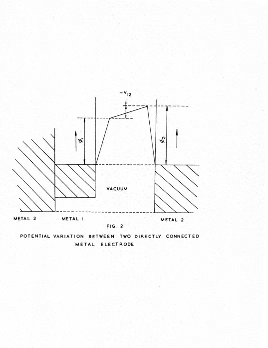
electron flow takes place across the junction between the two metals until the two Fermi levels reach a common energy level. Under these circumstances the potential variation across a vacuum gap between the two metals is shown in Pig.2. V_ , the potential across the vacuum, is known as the contact potential difference between the two surfaces of the
conductors and is given by the expression
-^12 = ^2 ~ ^1* (B'5)
where 0^ ^nd 0^ are the work functions of the two surfaces concerned.
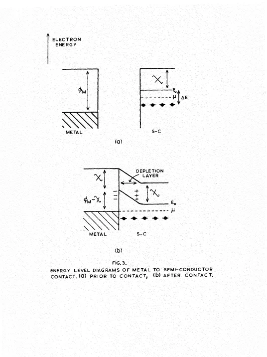
2.4. Thermionic emission.
In considering the thermionic emission from oxide cathodes based on the model of an 'n'-type semi-conductor, it is important to remember that the oxide is in contact with its base metal. Pig.3 shows the energy level diagram when contact is made to the base. Immediately the semi-conductor makes contact with the metal, electron donors near the surface of the semi-conductor lose their electrons to the metal until the two Permi levels coincide. This results in a layer of positive space charge in the
i M
METAL
(a)
S - C
DEPLETION LAYER
M E T A L S - C
[image:36.614.16.552.54.770.2](b)
FIG. 3.
26.
The emission current density equation for this model has been shown by Schottky(1940) to be similar to the Richardson-Laue-Dushman equation for emission from metals
jg = A(1 - r)T^. exp -e^/kT. (2.6) 3^ is the saturated current density, r is the electron
reflection coefficient at the emitting surface, 0 is the thermionic work function (X + " p)» ®Dd A is a constant given by:
A = 4TTm'k^e/h^ = 120 anrps/cm^/deg.^ (2.7) Substituting the value for (Eq- p.) from Eq.2.3. gives
j = B ( 1 - f G / a +"%) ( 2 . 8 )
where B = ( 2 Trm') (2.9)
Fowler has pointed out that these equations are only valid provided normal internal equilibrium is maintained in
the solid; emission is not an equilibrium process and there-fore these equations should never apply. In addition, the effects of the high resistance interface and the depletion layer formed at the base to oxide coating contact have been ignored. Some discussion will be given to these two points at the end of this section.
slope whose value is -(AE/2 From the energy diagram in Pig. 1 it can be seen that this quantity represents the thermionic work function at absolute zero. Similarly from Iq. (2.4) the so-called Richardson plot of log as a
function of 1/T should provide a measurement of the thermionic work function 0, However, account must be taken of the
fact that the work function 0 may be dependent on temperature (Becker and Brattain 1934). If the linear relationship
d^/dT ss a is assumed, then 0 = 0^ + aT, where 0 and 0^ are the values of the work function at T° and 0°E, respectively. Substituting this value of 0 into Sqo 2.6 gives
jg = A(1 - r)T^. exp -e(0^
i = A(1 - r)T^. exp -e(0 + aT)/kT (2.10)
= A(1 - r).exp -e( a/k). T^. exp -e(0^kT) (2.11)
The Richardson plot is therefore a straight line whose slope provides a measurement of the thermionic work function at 0°K, 0^, and whose intercept gives a value of the thermionic constant
AQ = A(1 - r). exp -e( a/k). (2.12) In addition to determining the thermionic work function at absolute zero, a fowler plot can provide an estimated value of the donor concentration from the intercept on the log
jg/T^ axis, log A' = 2ek^/^( 2ym') n^(l - r). (2.13) 3/2
98,
Direct calculation of either r or n^ being impossible,
Nottingham(1956) has estimated a value of 0.175 for (l - r) o A calculation based on the emission data of Hung(195J0) then
17 %
leads to a donor density of 2.4 x 10 per cm , By using
the emissioD data of Prescott and Morrison (1938) and their QQ
value for n^ of 10" , Bisenstein(1948) finds a value of 0.05 for (l - r); r = 0.95. Wooten' s( 1946) value of 10^® per cm"^ for n gives a value of 0.5 for (1 - r)o
On account of the very porous nature of the oxide cathode, accurate emission current density evaluation is very difficult since the actual emitting area is unknown*
Estimates of the external surface area will probably bear little relation to the total emitting area of the cathode, so that
measured values of log A are unreliable*
In his analysis of Hung's emission data, Nottingham applied corrections to the theory to include the effect of multiple
reflections on the diode characteristics and obtained a value of 112 amps/cm^/deg.^ for A, this value being in good agreement with the theoretical value of 120 amps/cra^/deg.^
Interesting results are obtained by considering the
emission from a cathode having zero reflection coefficient, a
18 ?
thermionic work function of 1.0 e¥., with n, = 10 per c m . b
density at 1000°K of 55 amps/cm^. Such high current densities have been observed only under microsecond pulse conditions, see Thomas(l930) , Sproull( 1945), Coomes( 1946) , and WrightC1947). From these observations it might be con-cluded that pulsed emission represents the true emission current density predicted by Eq. 2.8, and that measured D.C. emission current densities -represent a decayed state of the cathode. Emission decay effects will be discussed in detail in section 2.8.
The introduction of a depletion layer at the metal-coating interface, modifies the model of the oxide cathode
(Fig.3b) and leads to a possible explanation of the rectification properties observed in oxide oathodes by Wright(l947) and
t
K-2 Ui CK CK 3 u UJ o o z & o oSPACE CHARGE REGION
ACCELERATING \ FIELD REGION ^ RETARDING
FIELD REGION
A N O D E VOLTS F I G . 4 .
I4SO 9 7 0 725 5 8 0 o 4 8 0 T K. F I G . 5 .
REGION I , SEMICONDUCTOR CONDUCTIVITY IN CRYSTALS. RANGE E PORE C O N D U C T I V I T Y PREDOMINANT. RANGE m , PORE CONDUCTIVITY INHIBITED BY SPACE CHARGE. CURVE AA S E M I - C O N D U C T O R CONDUCTION A L O N E , CURVE BB PORE CONDUCTION ALONE WITHOUT
2.5 Voltage characteristics.
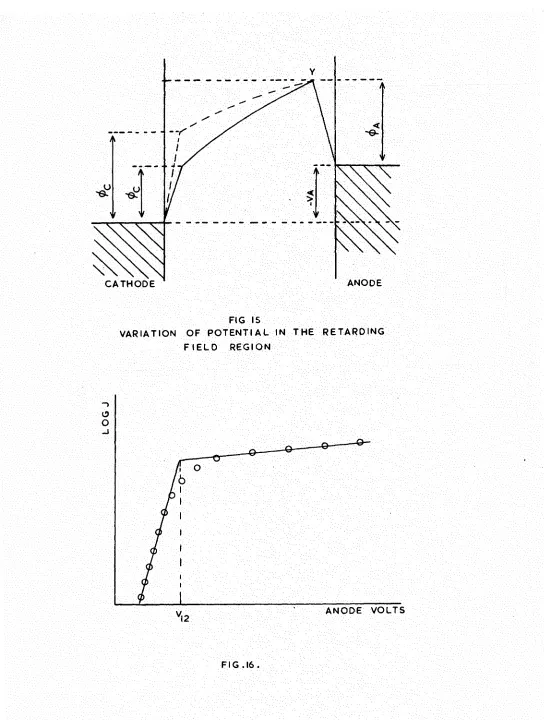
The general form of thermionic emission versus anode voltage curves for different cathode temperatures is shown in Fig.4, and can be divided into several distinct regions.
(a) Retarding potential region.
The retarding potential is the work required to carry an electron from a point just outside the emitter surface to a point just outside the collector surface, and may
result from an externally applied negative voltage, or from the contact potential difference between the anode and the cathode. For a plane parallel diode the current density
collected at an applied anode-cathode voltage V is given by jr = A(1 - r)T^ O.exp -(V + jZf^)/kT (2.14)
where is the anode work function, and G the anode electron reflection coefficient.
(b) Accelerating field region.
At low cathode temperatures where the emission current density is low enough for space charge effects to be
51.
interior and the emitted electrons. A reduction of work function resulting from a field B at the cathode surface was shown to be
1/2
0 K (el) . (2.15)
and the emission current density in this region j given by
= DQ exp (e^/B B^^^)/kT. (2.16)
where is the emission current density for zero applied field.
(c) Space charge region.
At higher cathode temperatures the space charge limited region becomes extended. Emission in this region range obeys the Langmuir-Child law, Ghilds(l911) , Langmuir( 1913) ,
(2.17) where is the space charge limited current, b is a
constant depending on the electrode arrangement, and V is the anode voltage.
2.6. Electrical conductivity.
cr with temperature T was of the form;
o- = a.exp -b/T. (2.18)
a and b being constants.
In 1949 Loosjes and Vink made a careful investigation of the electrical conductivity of a (BaSr)O cathode over the temperature range 500° to 1200°K. Their results showed that the conductivity over this temperature range could be divided into the three regions shown in Fig.5. Below 800°E the temperature dependence is small, the value of a the so-called activation energy in Eq.2.1@, varying from 0.6 to 0.09 eV. with increasing cathode activity, while in the range 800° to 1000°K there is a higher dependence of conductivity on temperature with activation energies from 2.2 to 0.8 eV. Above 1000°K the slope is again reduced.
Loos-jes and Vink explained these results in terras of two conduction mechanisms acting in parallel with one another. Low temperature conduction was attributed to normal conduction
through the particles of the oxide crystals, whereas conduction in the range 800° - 1000°K was explained by
The electrioal conductivity of an 'n' type
semi-conductor cTQ, is proportional to n^, the number of electrons
in the conduction band, and u, their mean mobility, so that
Oq = n^eu. (2.19)
Expressing in terms of electrical mean free path 1 which has a constant v#lue 1^ at a temperature T,(Maurer, 1945),
_ 4n„l e^
° 3C STira'lcT) 2°)
Substituting for n^ from Eg..2.4 givest
° I 2^''® , szp(_ ^3/2kT)
h
(2.21)
Providing AE/2 » kT, cr^ will be almost independant of the term in T^^^ and can be written:
CTQ = K exp -AE/2kT (2.22)
The plots of log Or against 1/T in the temperature range below
8 0 0 ° K which were found by Loosjes and Vink to be linear, will
then have a gradient a E / 2 » A s the temperature is increased
above 800°K, conduction of the electron gas in the pores of the oxide coating gradually swamps the semi-conduction
component.
The pore conduction process has been examined
a given applied potential and aathode temperature depends on the mean free path of the electrons, the pore size, the space charge in the pores, and the Schottky effect at the pore
surface resulting from the applied field. The expression derived for the pore conductivity is of the form
cr = E* ©xp (-^2AT) (2.23)
02 is a work function, which, by comparison with external thermionic emission, Loosjes and Vink identify as the Richardson work function, K' is a constant..
The combination of these two conduction mechanisms can be represented by:
era Aa^ + Ba^ = C e%p (-0 /kT) + D ezp ( - AE/2kT) (2.24) where A.B,G,D, are constants. If 0^ is the Richardson work function,
0 ^ — X , 80 that 0 2 ^ &B/2.
Over the whole temperature range these two processes act in parallel, but at low temperatures the solid semi-conduction mechanism dominates. In the high temperature range plots of
log eras a function of 1/T must be corrected for the semi-conduction process acting in parallel if an accurate value of 02 is to be obtained from the gradient.
An alternative explanation for the break in the
35.
However, if this was the case, activation energies in the high temperature region would be much less than the
Richardson work function, as energy would only be required to take electrons from the donor levels into the bottom of the conduction band. Loosjes and Vink(l949) and Nakai,
Inuishi, and Tsung-Chi(1955) reported values of the activation energy for the high temperature conductivity which agree
with the Richardson work function for thermionic emission in the same activation state. However, both these results should be considered cautiously. Loosjes and Vink measured the conductivities by pressing two cathodes into contact with one another. Emission measurements were made by seperating the cathodes and inserting an anode between them; this
process of seperation could almost certainly be expected to modify the cathode surfaces. On the other hand, the
conductivity measurements by Nakai, Inuishi, and Tsung-Chi (1955) have not been corrected for the parallel acting low temperature conductivity mechanism. Many workers obtain agreement to within 20^ between the activation energy for high temperature conductivity and the Richardson work
VS. RECIPROCAL TEMPERATURE. YOUNG (1952)
< * ) O X E (SI < 2
-BREAK POINT IN (b)
T H E R M O E L E C T R I C POWER VS. R E C I P R O C A L TEMPERATURE
YOUNG ( 1 9 5 2 )
(C)
H A L L C O E F F I C I E N T VS. RECIPROCAL TEMPERATURE
FORMAN (1954)
36.
Measurements of the: Hall coefficient and thermoelectric power provide other means of studying these conduction
processes. Theoretical models based on the pore conduction and semi-conduction suggested by Loosjes and Vink have been studied by Foreman! 1954) and Hensley(l952) , and these
theoretical results are in good agreement with the
experimental observations of Foreman(1954) and Young( 1952) . Both the Hall coefficient and the thermoelectric power show a distinct changes (Fig.6) in the temperature region
corresponding to a transition from pore to semi-conduction. Closely allied to the Hall effect is the phenomenon of magnetoresistancej this is the change of electrical
resistance brought about in a conductor or semi-conductor by the application of an external field. In agreement with theoretical predictions based on the Loosjes-Vink model, oxide cathodes have been shown (by Foreman 1954, and Metson 1958b) to exhibit strong megnetoresistive properties only when conduction is by way of the vacuum pores.
Pore conduction will involve successive collisions of electrons with the oxide particles, and the nature of such collisions, i.e. whether they are elastic, or non-elastic involving an energy transfer, has been investigated by Metson (1957)d. These investigations show clearly that the
electrons are therraionlcally emitted at the cathode base and travel to the surface, suffering regular non-elastic collisions with the pore walls.
The results of experimental investigations in the region below 800°K have not been is quantitative agreement with the
theoretical predictionso Measurements of the thermoelectric power by Young, although in qualitative agreement with
Hensley*s theoretical analysis based on the semi-conductor model, fail to agree quantitatively, and an additional ionic conduction process was suggested by Hensley to account for the discrepancy. Evidence for such a process was provided by HigginsonC1958). Metson was unable to detect the presence of this second semi-conduction process and attributes
Higginson's results to gas contamination in the cathode. Experiments with both inert gases and oxygen indicate that the solid semi-conduction mechanism in the oxide cathode is a surface phenomenon resulting from a layer of excess
alkaline earth atoms, as in de Boer's model (1935). Hughes and Ooppola( 1952) and Hannay et al.(l949) have found
exceptionally low activation energies of the order 0.05 eV. with the cathode below 800°K and surrounded by a high pressure inert gas. Upon introducing oxygen to an oxide cathode,
i o n c u r r e n t
-(AMPSxaxio*^)
20-i s e c
i sec
20 40
t i m e in s e c s ,
f i g . 7 .
h g o e v o l u t i o n f r o m a b a r i u m o x i d e c a t h o d e a t i 0 8 5 ° k
f a r a d a i c m o d e
100 200 300
c u r r e n t , m a .
4 0 0
p r o b a b l e r e l a t i o n s h i p b e t w e e n d i s s o c i a t i o n r a t e a n d c u r r e n t
instantaneous poisoning. The effect of the inert gas would be to prevent residual oxidising gases reaching the alkaline earth atoms on the surface. Oxygen would immediately
oxidise any excess alkaline earth atoms on the surface and hence produce the observed decay in conductivity.
Current dependant processes.
Electrolysis occuring in oxide coated cathodes was investigated by Becker(1929), and shown to produce free metallic barium and oxygen. Drawing temperature limited
emission from the cathode resulted in oxygen evolution, whereas when the current had been reversed metallic barium was found on the surface. As a result of investigations to study the observed pulsed-emission decay in oxide cathodes, Sproull(1945) suggested a flow of barium ions away from the surface dependant on the thermionic current density.
Plumlee(l956) has described the evolution of H , H 0, 2 2 CO, Og, and CO^ from a cathode at 1 0 3 5 u n d e r various
applied potentials. Evolution of molecular oxygen was found to be proportional to the applied potential and inversly
59.
For a given applied field, the CO evolved was found to be
2
proportional to the residual COg pressure in the system* A filament failure in the experimental system prevented
detailed observations on H evolution, although some voltage dependant effects were observed.
From these results Pluralee suggested that apart from the usual reaction of barium oxide with water vapour:
BaO + EgO -^Ba(OH) ,
at low vapour pressures another reaction might be expected
of the form:
/ \ + 2+ + BaO + H O -^BaCOH) + 0 + H
^»Ba(OH.e) + 1/8.0 + 1/2. Hg.
This reaction indicates the formation of a new type of hydroxy1 ion having attached to it an extra electron which Plumlee suggests is the electron donor centre in the oxide cathode. However the above reaction has not been verified experimentally. Active electron donors of the (OH.e) type would require the partial pressure of H O in the system to be of the order 10 mmHg. which is not unrealistic.
The most exhaustive study of electrolitic and
dependant dissociation does occur in the oxide cathode, it is not Faradaic. Pig.8 shows the probable variation of
dissociation rate with current (Metson and Macartney 1960a). The hypothesis presented by Metson to esqjlain this dissociation is as follows; an applied field accelerates electrons through the vacuum pores of the cathode finally resulting in
non-elastic collisions with the oxide particleso If during such a collision energy transfer raises the temperature of an oxide molecule above a critical temperature T^, the molecule
dissociates, and the dissociated ions are seperated by the applied field. In this hypothesis the seperation between
oxide particles in the matrix is considered to be quite random, so that a lower critical field exists which will accelerate an electron over the longest free path in the matrix and
produce dissociation when the electron collides with an oxide particle.
41.
that electrolytic dissociation produced a rise in the matrix resistance of an 8-type assembly fitted with platinum cores, and that under steady current flow conditions the resistance finally acquired a constant value which was higher thah that of the matrix under zero load conditions. When the current flow was removed from the matrix the resistance returned to its original value.
The increase in matrix resistance is attributed by Metson to an increase in the number of negative oxygen ions in the matrix. Under the Influence of the applied field, dissociated barium and oxygen Ions drift to the cathode and anode cores where they discharge to the atomic form. The Increased
concentration of the respective atoms at the anode and cathode cores gives rise to a slow dlffucion back to the
centre of the matrix resulting in their recombination as barium oxide molecules. The matrix resistance reaches a steady
state when dynamic equilibrium exists between the dissociation and recombination rates.
tip in the cathode matrix:, and compared with the S-type assembly, the emission decay will be reduced. Removing the current load will result in a cathode of increased
activity due to the excess barium produced by the electrolytic dissociation.
Okumura and Hensley (1963) have proposed a mobile acceptor theory to account for the activation of oxide coated cathodes. They suggest that in the initial stages of cathode processing Schottky vacancy pairs are produced, and that being positively and negatively charged, these vacancies act as acceptors and donors, respectively, in the oxide matrix. On the basis of their experimental results, Okumura and Hensley propose that during activation of the cathode free barium is produced by reaction of the barium oxide with the reducing agents in the nickel base, and that the presence of this free barium can result in anihilation of acceptors, thus increasing the
cathode activity by removing the acceptors (barium vacancies) which compensate the donors (oaygeo vacancies)
On this model activation by drawing current proceeds with a number of negatively charged acceptors being moved to
43.
of an oxide particle, the neutral acceptor releases an oxygen atom, the net result being a fall in the acceptor concentra-tion.
The above theory has no distinct advantages over other theories, but merely proposes an alternative mechanism by
which a donor density can be established in the oxide cathode. The experimental results given by Okumura and Hensley by no means establish this theory, and it seems that in the light of evidence so far available, activation of the oxide cathode by drawing current is due to electrolytic dissociation of the oxide, the oxygen being evolved and leaving an excess of the alkaline earth metal in the matrix.
2.8. Thermal stability and evaporated products.
The only 'internal' investigations of the thermal
stability of alkaline earth oxides are those of letson(1961)a. Measurements of the electrical conductivity of an 8-type
assembly with platinum cores indicate that purely thermal dissociation does occur in a (BaSr)O matrix, and that under the influence of an applied field the dissociated products are accumulated in the anode and cathode sections of the matrix. Negative oxygen ions in the anode section produce
Experiments with single oxides in the same system show a rise in Rg/R^ as a result of purely thermal treatment at 1020°K, only in the case of strontium oxide. Barium oxide shows only a slight rise in Rg/E^o indicating that baripm oxide on a platinum base can be regarded as thermally stable. Thus in the case of the mixed oxides the observed
dissocia-tion is that of the strontium oxide component of the matrix. Many observations have been made on the products
evaporated from cathodes of mixed and single oxides, Plumlee and Smith(l950), Aldrich(l951) , Pei.chowitch(l954) , Metson (l96l)b. With the exception of the work by Metson, the evaporated products have been studied using high resolution mass spectrometric tedhnlquea. Metson identified the
evaporants by their electrical conductivity, optical
properties, and reactions on exposure to air. As Rittner (1953) suggested in his theoretical study of the chemistry of oxide cathodes, the products evaporated from any given alkaline earth oxide depend to a great extent on nature of the metal base.
Mixed oxides of (BaSiOa)O in the ratio 49t44:7 on active nickel have been investigated by Plumlee and Smith* At
45,
calcium. On pure platinum or nickel the mixed oxides were shown by Pelchovdtch and Plumlee and Smith to evaporate mainly as barium oxide*.
(BaCa)O and (BaSr)O coated onto pure platinum or nickel have been found by Pelchowitch to evaporate mainly as barium oxide, although Metson's evaporation experiments showed the evaporation from a (BaSr)O system to be predominantly
strontiumo
When consideration is given to the products evaporated from single oxides on platinum the results are some to a extent surprising; the main evaporant from calcium oxide was found by Pelchowitch to be neutral calcium, and to a lesser extent calcium oxide and positive calcium ions, while strontium was observed to evaporate as strontium metal,
strontium oxide, and positive strontium ions, in the same proportions as the calcium oxide evaporants. However, in
the case of barium oxide dissociation does not take place, the only evaporant being barium oxide. At higher temperatures in the region 1500°K, in addition to BaO, lesser quantities of Ba_0 , Ba 0, and Ba 0 are evaporated.
TABLE 2.1.
0x1 de H (eV.) H - LgteV,)
BaO 5.^9 5.8 1,9
8rO 5.4 6.1 0.7
GaO 6.5 6*6 0.1
Lg heat of sublimation H dissociation energy
Table 2.1 gives the heats of sublimation Lg and the dissociation energies H of barium oxide, strontium oxide, and calcium oxide. From Table 2ol it is not suprising to find that barium oxide is the more stable of the three oxides. As Metson(l953) has recently pointed out, the degree of
dissociation as measured by the ratio of metal to oxide in the sublimate is dependant on the energy difference H - Lg rather than on H alone.
The combined effect of a hot cathode and an applied anode potential of about 30 volts has been shown by Metson and
Woodgate(l962)a to have disasterous effects on the oxide
47,
electrons between collisions, and causing intense heating and luminescence of the oxide particles. At still higher applied voltages this internal electron bombardment produced incandescence at small points in the cathode, resulting
finally in a partially eroded cathode surface. During this latter process violet and less frequently green flashes were observed, indicating excited states of strontium and barium, respectively. Further increases in the electron energy were found to result in total disruption of the matrix. Fused, positively charged particles were ejected from the cathode leaving a fused oxide layer covered with strontium and barium metal. Observations of the trajectories of the ejected
particles with and without the presence of magnetic fields indicate that the fused particles are carried out of the disrupting cathode in ajet of negative oxygen ions, and that they receive their positive charge from the dissociated metal ions.
The very high electron energies required to cause total disruption were obtained by holding the current through the
coating constant, and then decreasing the cathode temperature. Since
I = env
A
of the electrons, decreasing the cathode temperature at constant produces a decrease in the number of carriers and therefore an increase in v.
2.S. Emission decay effects.
For a fixed cathode temperature and anode potential the emission current from a fully activated oxide cathode is observed to decay with time. The time scale of this decay allows a division into two catagories; long term emission decay and millisecond decay.
Long term emission decay is probably caused by the return of material from the anode and this has been mentioned in
section (2.6). Such decay is observed fo$ certain definite values of the anode potential in oxide cathode valves.
Metson(l949) has reported emission poisoning at anode
potentials of 5, 10, and 16 volts. From the work of Jacobs (1946) who derived a tentative relationship between minimum electron energy for dissociation and the heat of formation of the compound concerned, these voltages are thought to
correspond to dissociation energies; the 5 volt effect to the dissociation of BaO or SrO, the 10 volt effect to the dissociation of either BaCl^ or SiGl and the 16 volt effect
2 2
49 c
ionisation phenomena. fhe electronegative component formed by these dissociations may then result in the observed cathode poisoning.
A second emission decay phenomenon, having a time constant of the order of a few milliseconds, was first observed by
Blewett(l939), and attributed to a depletion of barium atoms from the cathode surface. Later investigations by Sproull (1945) confirmed Blewett's findings. Kergaard(l952) proposed a mobile donor theory to account for the millisecond decay phenomenon. Under an applied field the partially ionised
donors formally distributed uniformally throughout the coating, would drift away from the cathode surface, leaving a donor
depletion layer. For a fixed anode potential the drift of charged donors is counterbalanced by a diffusion of donors
under the influence of the newly created concentration gradiento The net result is a depletion of donors from the surface
resulting in an increase in the work function of the cathode® On removing the applied field the former uniform distribution is restored by diffusion.
to the pulsed current, the saturation current density was increased.
Hensley's mobile acceptor theory (1963) can also explain millisecond decay. All the essential features of Nergaard's
theory are retained, except that, being negatively charged, the acceptors are attracted to the surface when a positive potential is applied.
Thin film emission.
All studies of thermionic emission from monolayer films of evaporated barium oxide indicate a similarity between the emission properties of such films and those of thick sprayed oxide coated cathodes. (see for example Davisson and Pidgeon 1920, Moore and Allison 1950, Russell and Bisenstein 1954, Metson 1957, Florio 1963)
The formation of a thin film of alkaline earth oxide on the metal base of an oxide cathode has been described by
electrons thermiooically emitted from the cathode. On this model the porous matrix has three functions; to limit the
total emission by the space charge effect of electrons emitted from the pore walls, to maintain the thin emitting film which is being continually condensed and re-evaporated, and to
protect the core emitter from gas attack.
Russell and Bisenstein consider that the thin film of
oxide on the base metal only makes a contribution with the rest of the matrix to maintaining an electron gas density in the pores, these electrons being continually absorbed and
re-emitted from the pore walls.
CHAPTER III
SUBLIMATION AND ADSOEETION PROGSSSES*
5.1. IntroduGtioQ.
The main interest of this work is the sublimation and adsorption of barium oxide. In this chapter consideration will be given to sublimation and adsorption processes, and
the modification of the adsorbent work function by adsorbates. The various methods available for estimating the thickness of adsorbed films will also be discussed.
5.2. Sublimation.
Sublimation is said to take place when a solid changes directly to vapour without the presence of a liquid phase. The condition necessary for sublimation is that the solid
should be maintained at a pressure below that corresponding to its triple point. If the solid is then heated, sublima-tion takes place.
molecules and so tending to lower the temperature of the solid. The energy necessary for a molecule to leave the surface is called the activation energy of sublimation, and this quantity can be related to the tsi^erature of the solid and the rate of sublimation by an Arrehenius equation| in any reversible reaction the variation of the velocity constant c with the temperature T°K in either direction was shown by Arrehenius to obey a relation of the foira:
d/dT. ln(c) = A/kT^, (3.1)
where k is Boltzmann's constant, and A can be considered as an energy of activation. Integrating Eq. 5.1 ;
c = C exp -A/kT. (3.2)
where C is a constant of integration. Thus, taking the case of sublimation, where W is the rate of sublimation in grams per square centimeter per second, and Lg is the activation energy of sublimation,
W = G exp -Lg/kT. (5.5)
The value of the activation energy of sublimation can be deduced from a graph of log W as a function of l/T,
Lg = 1/5040. d(log W)/d(l/T). eV. (3.4)
3.3 Condensation.
KBud8en(l909), and Langrntiir( 1917) , established that a lower critical substrate temperature was necessary before
condensation could take place. Prom observations with cadmium and mercury vapour Wood and Knudsen concluded that when atoms strike a glass surface which is above the critical
temperature for condensation, they are reflected from the surface. This reflection may result from either elastic or non-elastic collisions with the surface, but in either case the reflection is a direct result of the atom striking the surface initially.
The results of Langmuir's experiments indicated a process of condensation and re-evaporation, rather than
reflections by increasing the intensity of the vapour stream hitting the condensing surface Langmuir found that the
critical temperature for condensation could be increased. On the basis of Langmuir's theory, condensed atoms would have a finite life on the condensing surface before being
re-evaporated. For temperatures below the critical value, the life-time of an atom on the surface may be sufficiently long to enable another condensed atom to collide with it, and so form an atomic pair. The atomic pair forms a nucleus with a much longer mean life on the surface than the single atom.
55.
and Langmuir to condensation on surface contaminated by gases and grease from the vacumn systems. When consideration is given to the vacutim conditions available for these early investigations, it is possible that such contamination did exist, and that it might have resulted in a lowering of the surface binding forces. On clean degassed metals the weakest vapour intensities should condense, and the structure of the deposited layer can be expected to be similar to the crystal lattice of the substrate.
A flux of atoms or molecules can be condensed either as mono-atomic or raono-molecularlayers, or aggregates. [The
conditions leading to either structure have been stated by Appleyard(1937)s- "Let L be the latent heat of evaporation of
condensed atoms or molecules from the substrate, and the latent heat of evaporation from the condensing solid. Then, if L<Ljjj the aggregate form has the lowest energy and is the most stable. If the monolayer form is the most stable."
Observations made on thin films of cadmium and mercury by lstermann( 1925) , Cockcrof t( 1928) , and Holland( 1956) are in good agreement with this statement.
molecules or atoms are trapped at low temperatures. Before the trapped molecules or atoms can be mobile over the surface they must have sufficient kinetic energy to surmount the
potential barriers between pockets. Since this kinetic
energy is much less than the energy required for re-evaporation, migration can occur at temperatures well below those at which
re-evaporation takes place*
For relatively high intensity metal vapour beams. Levinstein(1949) observed a stronger tendency for the
condensed films to form monolayers rather than aggregates.. Levinstein explained these observations in terras of surface mobility. Atoms or molecules will move over the surface until they collide with other atoms or molecules and thereby loose their mobility. In the case of high intensity beams, atoms arriving on the surface either collide with each other, or with existing atom pairs; since there is a greater
57.
5.4 Chemical and physical adsorption.
Adsoiption phenomena are frequently divided into two classes; chemical adsorption (chemisorption), and physical adsorption. In principle these two processes can be
distinguished by defining chemical adsorption as occurring when the binding of the molecule to the surface is caused by an exchange or sharing of electrons. The forces producing chemisorption are the same as those producing chemical
combinations, so that during chemisorption the heat evolved (the heat of chemisorption) is the heat expected from a chemical reaction between the adsorbate and the adsorbento Since chemisorption is a surface reaction taking place between
the adsorbent and the adsorbate, it follows that only one chemlsorbed layer can be formed; chemisorption is always unimolecular.
The forces of interaction in physical adsorption are Van der Waal's forces in their widest sense* This Includes quadrupole, permanent dipole, and induced dipole attraction. Such forces are weak in comparison with chemisorption forces, the heat of physical adsorption being of the same order of magnitude as the heat of liquifactlon of gases. When