A L L - C E L L U L O S E C O M P O S I T E L A M I N AT E S : T H E P R O C E S S I N G - S T R U C T U R E - P R O P E R T Y R E L AT I O N S H I P S F R O M T H E M A C R O - T O T H E
N A N O S C A L E
Jan Wolfgang Dormanns
A thesis submitted in partial fulfilment of the requirements for the Degree of Doctor of Philosophy in Mechanical Engineering in the
“For all knowledge and wonder (which is the seed of knowledge) is an impression of pleasure in itself.” — Sir Francis Bacon (The Advancement of Learning, 1605)
Dedicated to my son Samuel with your endless curiosity and happiness. Never stop exploring my little adventurer!
C O N T E N T S
Acknowledgements v
Abstract vii
List of Figures xii
List of Tables xxiii
1 i n t r o d u c t i o n 1
1.1 Background . . . 1
1.1.1 Composites, bio-based composites and green composites 1 1.1.2 Single polymer composites . . . 5
1.1.3 All-cellulose composites . . . 6
1.2 Research motivation and objectives . . . 17
1.2.1 Motivation . . . 17
1.2.2 Objective 1: Upscaled manufacturing and size effect in all-cellulose composite laminates . . . 18
1.2.3 Objective 2: Aqueous sodium hydroxide/urea solution as alternative solvent for solvent infusion processing . . 18
1.2.4 Objective 3: Removal of solvent from all-cellulose com-posite laminates . . . 19
1.2.5 Objective 4: Individual structural and mechanical char-acterisation of fibre and matrix phases in all-cellulose composite laminates . . . 20
2 l i t e r at u r e r e v i e w 23 2.1 Cellulose . . . 23
2.1.1 Molecular structure . . . 23
2.1.2 Secondary structure . . . 25
2.1.3 Crystal structure and polymorphy . . . 27
2.1.4 Amorphous cellulose . . . 29
2.1.5 Crystallinity . . . 30
2.2 Cellulose dissolution . . . 31
2.2.1 Derivatising cellulose solvents . . . 31
2.2.2 Non-derivatising cellulose solvents . . . 32
2.2.3 Cellulose dissolution in aqueous sodium hydroxide solu-tion . . . 36
2.2.4 Cellulose dissolution in ionic liquids . . . 41
2.2.5 Regeneration of dissolved cellulose . . . 44
2.3 Cellulose fibres . . . 49
2.3.1 Natural fibres . . . 49
2.3.2 Man-made cellulose fibres . . . 52
3.1 Materials . . . 65
3.1.1 Cellulose precursor . . . 65
3.1.2 Solvents . . . 66
3.2 Preparation of all-cellulose composite laminates . . . 67
3.3 Preparation of cellulose films . . . 69
3.4 Materials characterisation . . . 70
3.4.1 Mechanical testing . . . 70
3.4.2 Microscopy . . . 70
3.4.3 Density . . . 71
3.4.4 Determination of matrix and void fraction . . . 72
3.4.5 Wide angle X-ray diffraction . . . 73
3.4.6 Fourier transformed infrared spectroscopy . . . 75
3.5 Statistics . . . 76
4 s i z e a n d s c a l e e f f e c t s i n a l l-c e l l u l o s e c o m p o s i t e l a m i nat e s 77 4.1 Introduction . . . 77
4.2 Experimental procedures . . . 79
4.2.1 Preparation of all-cellulose composite laminates . . . 79
4.2.2 Materials characterisation . . . 80
4.3 Results and discussion . . . 82
4.3.1 Microstructure . . . 82
4.3.2 Tensile behaviour . . . 82
4.3.3 Damage evolution in all-cellulose composite laminates . 84 4.3.4 Properties of all-cellulose composite laminates as a func-tion of laminate thickness . . . 88
4.3.5 Positive size effect on the tensile strength of all-cellulose composite laminates . . . 96
4.3.6 Size effects in composites and polymers . . . 98
4.3.7 Initiation of failure in all-cellulose composite laminates .103 4.3.8 Scale effects in all-cellulose composite laminates . . . . .104
4.4 Summary . . . .104
5 s o lv e n t i n f u s i o n p r o c e s s i n g u s i n g a q u e o u s s o d i u m h y d r o x i d e/u r e a s o l u t i o n 107 5.1 Introduction . . . .107
5.2 Experimental procedures . . . .109
5.2.1 Preparation of all-cellulose composite laminates by solvent infusion . . . .109
5.2.2 Optimisation of processing parameters . . . .111
5.2.3 Solubility of rayon in aqueous sodium hydroxide/urea solution . . . .112
5.2.4 Preparation of unreinforced cellulose films . . . .113
5.3 Results and discussion . . . .114
5.3.1 Effect of infusion temperature . . . .114
5.3.2 Effect of continuous cooling during infusion . . . .118
5.3.3 Effect of dissolution time on the microstructure . . . . .123
5.3.4 Effect of dissolution time on the fine structure of cellulose126 5.3.5 Effect of dissolution time on the mechanical properties .131 5.3.6 Characteristic stress-strain behaviour . . . .134
5.3.7 Influence of increasing laminate thickness . . . .137
5.3.8 Effect of infusion pressure . . . .141
5.3.9 Processing of all-cellulose composite laminates by im-mersion in aqueous sodium hydroxide/urea solution . .144
5.3.10 Comparison between ionic liquids and aqueous sodium hydroxide/urea solution for solvent infusion processing149 5.4 Summary . . . .150
6 r e m ova l o f s o lv e n t f r o m a l l-c e l l u l o s e c o m p o s i t e l a m i nat e s 153 6.1 Introduction . . . .153
6.2 Experimental procedures . . . .157
6.2.1 Conductivity and pH measurements . . . .157
6.2.2 Fourier transformed infrared spectroscopy . . . .157
6.2.3 Elemental analysis . . . .158
6.3 Results and discussion . . . .159
6.3.1 Monitoring of solvent removal by washing in distilled water . . . .159
6.3.2 Analysis of solvent removal by Fourier-transformed in-frared spectroscopy . . . .162
6.3.3 Analysis of solvent removal by elemental analysis . . . .164
6.4 Summary . . . .173
7 i n d i v i d ua l c h a r a c t e r i s at i o n o f t h e f i b r e a n d m at -r i x p h a s e s i n a l l-c e l l u l o s e c o m p o s i t e l a m i nat e s 175 7.1 Introduction . . . .175
7.2 Experimental procedures . . . .180
7.2.1 Sample preparation . . . .180
7.2.2 Synchrotron-based Fourier-transformed infrared micro-spectroscopy . . . .181
7.2.3 Analysis of Fourier-transformed infrared spectra . . . .182
7.2.4 Nanoindentation . . . .184
7.2.5 Atomic force microscopy . . . .186
7.2.6 Transmission electron microscopy . . . .189
7.3 Results and discussion . . . .190
7.3.1 Microstructure . . . .190
7.3.3 Synchrotron-based Fourier-transformed infrared micro-spectroscopy . . . .199 7.3.4 Nanoindentation . . . .213 7.3.5 Influence of the individual phases on the laminate
prop-erties . . . .219 7.4 Summary . . . .223 8 d i s c u s s i o n o f m e t h o d o l o g y a n d f u t u r e w o r k 227
8.1 Specimen preparation for microscopy . . . .227 8.2 Determination of void and matrix fractions . . . .232 8.3 Upscaled cooling setup for solvent infusion processing using
aqueous sodium hydroxide/urea solution . . . .235 8.4 Alternative methods for the characterisation of the individual
fibre and matrix phases . . . .238
9 c o n c l u s i o n s a n d o u t l o o k 241
9.1 Concluding remarks . . . .241 9.2 Outlook . . . .246
b i b l i o g r a p h y 251
Of the gladest moments in human life, methinks is the departure upon a distant journey to unknown lands. — Sir Richard Francis Burton (1856)
A C K N O W L E D G E M E N T S
Even though the world was quite different and far more unexplored in Bur-ton’s days, it was with slightly nervous joy that Katharina and I headed off to Christchurch in 2012 and it is with a laughing and a crying eye that I see this thesis being submitted. New Zealand has been a fantastic home in the past three years and I want to thank all those who helped me during this time.
I wish to express my most sincere gratitude to Dr. Mark Staiger, Prof. Dr. Jörg Müssig and Dr. Benoît Duchemin for their valuable supervision. Thank you for all the advice and help over the past years, it was a great experience. I want to thank all the technicians at UC for their great assistance, es-pecially Kevin Stobbs, Mike Flaws, Helen Devereux, Gary Turner, Manfred Ingerfeld and Jan McKenzie.
A big thanks to the MacDiarmid Institute for funding my research trips, the MacDiarmid Emerging Scientist Association for great workshops and connecting students all over New Zealand, and Dr. Michelle Dickinson at the University of Auckland for granting access to the nanoindenter.
My thanks also go to Dr. Céline Picard and Vincent Loisel for their as-sistance during my stay in Le Havre; and Dr. Mark Tobin and the IR-team at the Australian Synchrotron, and the Royal Society of New Zealand for funding the synchrotron experiments and travel assistance to Melbourne (AS151/IRM/ Proposal 9060).
A special thanks to Dr. Tim Huber and Dr. Jeremias Schuermann for their help and advice, as well as countless discussions on ACCs; and to all the other students I had the honour to share an office with for the great atmo-sphere. I also want to thank Felix Weiler, Tom Pawley and Christian Hannes for their contributions during their internships in our research group.
Thanks to André Miede for providing the classic thesis style and the LA
TEX-community for discussing every single typesetting problem and all the en-ergy that goes into web fora. Also a big thanks to all open source developers for making great software available.
Finally, I want to thank all my friends here in New Zealand, back home in Germany and all over the world, thanks for being the wonderful people you are. I want to show my deepest gratitude to my parents and my fam-ily, thanks for all your trust and confidence, supporting me wherever I go, whatever I do and always being there for me when I need you the most.
A B S T R A C T
Cellulose is an excellent resource for the manufacture of sustainable materials, due to its availability and biodegradability. All-cellulose composites (ACCs) are an emerging class of bio-based composites in which both the fibre and matrix phase consist of cellulose. Thereby, ACCs overcome the chemical incompatibility often encountered when hydrophilic cellulose is used as reinforcement of hydrophobic polymer matrices in bio-based composites.
The mechanical properties of ACCs are reported to exceed those of traditional bio-based composites, which makes ACCs a promising material in the search for an alternative to petrochemical-derived thermoplastics. However, the manufacture and characterisation of ACCs has been limited to thin films (< 1 mm). Recently, solvent infusion processing (SIP) based on partial dissolution of cellulose fibres in an ionic liquid (IL) has been developed. SIP presents a pathway that allows the manufacture of thick ACC laminates (> 4 mm), which widens the range of potential applications. The aim of this work was the characterisation of the structure and properties of ACC laminates from the macroscopic laminate scale down to the individual fibre and matrix phases on the microscopic scale.
fail-ure to tough and high-strain failfail-ure with increasing thickness and a scale effect of increasing crystallinity towards the core of thick ACC laminates was observed.
SIP has been developed using imidazolium-based ILs, which offer a high cel-lulose solubility and facilitate controlled dissolution by adjusting the processing temperature. However, ILs are also known to be toxic and non-biodegradable, mak-ing them non-ideal solvents for manufacturmak-ing a green material. In this work the use of an aqueous 7 wt. % NaOH/12 wt. % urea solution (NaOH/urea) as cellulose solvent for SIP has been explored as an environmentally friendly and cost-effective alternative to ILs. The effect of infusion temperature, dissolution time and cooling during processing were investigated. NaOH/urea facilitated rapid processing of ACC laminates with partial dissolution achieved in 5 min and when compared to IL-processed laminates a similar Young’s modulus in the range of 7 to 8 GPa and a 28 % increase in ultimate tensile strength to 123 MPa was found. Cooling the SIP setup and the solvent to -12 °C prior to infusion and continuous cooling during in-fusion were required to achieve homogeneous and optimum mechanical properties. Fourier-transformed infrared spectroscopy (FTIR) and elemental analysis were utilised to confirm the complete removal of IL and NaOH/urea from thick ACC laminates by washing in distilled water. Measuring the conductivity of the washing bath was established as a measure of the solvent content and to determine comple-tion of solvent removal from ACCs.
D E C L A R AT I O N
I declare that this dissertation is my own unaided work. It is being submitted for the degree of Doctor of Philosophy at the University of Canterbury. It has not been submitted for any other degree or examination in any other University.
P U B L I C AT I O N S
The work presented in this thesis includes the following publications:
Chapters1– Introduction – and2– Literature Review – include passages of the following book chapter:
Title: “From Cellulose Dissolution and Regeneration to Added Value Applic-ations – Synergism Between Molecular Understanding and Material Devel-opment”
Authors: Poonam Singh, Hugo Duarte, Luís Alves, Filipe Antunes, Nicolas Le Moigne,Jan Dormanns, Benoît Duchemin, Mark Peter Staiger and Bruno Medronho
Book: “Cellulose”, ISBN 978-953-51-4411-3 Publisher: IntechOpen, Rijeka, Croatia
Material covered in Chapter4– Size and scale effects in all-cellulose com-posite laminates – has been accepted for publication subject to amendments, revision under review as of 24.02.2016:
Title: “Positive size and scale effects in all-cellulose composite laminates” Authors: Jan Dormanns, Felix Weiler, Jeremias Schuermann, Jörg Müssig, Benoît Duchemin, Mark Peter Staiger
Material covered in Chapter5– Solvent Infusion Processing Using Aqueous Sodium Hydroxide/Urea Solution – has been peer-reviewed and published: Title: “Solvent Infusion Processing of All-Cellulose Composite Laminates Us-ing Aqueous Sodium Hydroxide/Urea Solution”
Authors: Jan Dormanns, Jeremias Schuermann, Jörg Müssig, Benoît Duch-emin, Mark Peter Staiger
L I S T O F F I G U R E S
Figure 1 (a) Natural fibre-reinforced components in Mercedes S class (Bledzki et al.,2006, reproduced with kind per-mission of John Wiley and Sons). (b) Bioconcept car based on a Volkswagen Scirocco with natural fibre-reinforced chassis (www.fourmotors.com, 21.05.2015). 3 Figure 2 Processing of ACCsvia(a) the 1-step method and (b)
the 2-step method (Adapted fromHuber et al.,2012c). 8 Figure 3 Comparison of mechanical properties of (a) isotropic
and (b) unidirectional bio-based composites and ACCs. Underlying data was presented in the review ofHuber et al.[2012b], updated with more recently published studies on isotropic ACCs [Halonen et al.,2012;Huber et al.,2012a;Shibata et al.,2013a,b;Larsson et al.,2014]. 13 Figure 4 Setup of the solvent infusion process (SIP) as developed
byHuber et al.[2012a]. . . 16 Figure 5 Molecular structure of cellulose (adapted fromPinkert
et al.,2010). . . 24 Figure 6 Hierarchical structure of cellulose from microfibril to
tree (Image credit: Mark Harrington, University of Canterbury). . . 25 Figure 7 Schematic of cellulose chains (hypothetically) arranged
in different degrees of order, from perfectly crystalline to fully amorphous (adapted fromHowsmon and Sis-son,1954). . . 26 Figure 8 Models for the supermolecular structure of (a)
crystal-line and (b & c) semicrystalcrystal-line cellulose (Fink et al., 1995; reproduced with kind permission of Springer Science and Business Media). . . 27 Figure 9 Interconversion of cellulose polymorphs (adapted from
O’Sullivan,1997). . . 28 Figure 10 Hydrogen bonding pattern of cellulose I and
cellu-lose II (adapted fromO’Sullivan,1997). . . 29 Figure 11 (a) Chemical structure of NMMO [Olsson and Wesman,
2013]. (b) Phase diagram of the NMMO/water solvent system [Biganska and Navard,2003]. . . 34 Figure 12 Solubility of modified cotton in aqueous NaOH
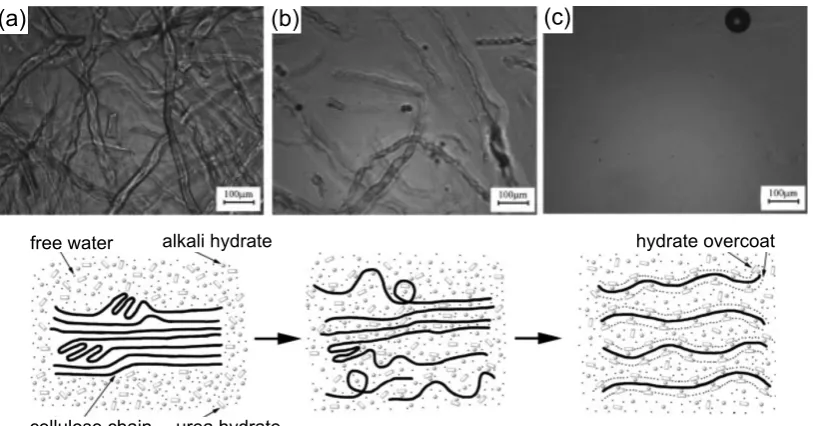
Figure 13 Ternary phase diagram of cellulose-NaOH-water mix-tures developed bySobue et al.[1939]. Red circle marks the “Q-region” of cellulose solubility (adapted from Navard et al.,2012). . . 37 Figure 14 Optical microscopy and schematic of the dissolution
process of cellulose in aqueous NaOH/urea solution precooled to -10 °C from (a) the initial undissolved to (b) the swollen and (c) fully dissolved state (Cai and Zhang,2005; with kind permission of John Wiley and Sons). . . 40 Figure 15 Van der Waals force representation of the cellulose
chain shown perpendicular (top) and parallel (bot-tom) to the equatorial direction of the glucopyranose rings with hydrophobic and hydrophilic parts indic-ated by ellipses. Oxygen atoms are shown in red, non-polar carbon atoms in black, hydrogen atoms have been omitted for clarity (adapted from Bergenstrahle et al.,2010, andMedronho and Lindman,2014b; with kind permission of Elsevier). . . 41 Figure 16 Commonly used cations of ILs used for cellulose
dis-solution (Olsson and Wesman,2013). . . 42 Figure 17 Interaction of an imidazolium-chloride ionic liquid
with cellulose (based on Feng and Chen, 2008, and Olsson and Wesman,2013). . . 43 Figure 18 Schematic model for the structural formation of
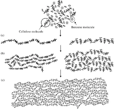
cel-lulose by regeneration in water: (a) formation of mo-lecular sheets by hydrophobic stacking and van der Waals forces; (b) piling up of the molecular sheets by hydrogen bonds to form seeds of crystalline (left, (110) crystal lattice plane indicated) and amorphous domains (right); (c) contact and sticking together of the structural units to form regenerated cellulose (re-produced from Miyamoto et al., 2009, with kind per-mission of Elsevier). . . 46 Figure 19 Schematic model for the structural formation of
Figure 21 Schematic of the cell wall structure of plant fibres, dif-ferent microfibrillar angles are outlined in the second-ary cell wall layers (Adapted fromKlemm et al. 2005 andBledzki and Gassan 1999). . . 52 Figure 22 Processing steps in the production of regenerated
cel-lulose fibres (www.lenzing.com, 19.02.2015) . . . 54 Figure 23 Processing steps of regenerated cellulose fibresviathe
viscose and Lyocell process (adapted fromWoodings, 2001, andKlemm et al.,2005). . . 57 Figure 24 Representative stress-strain curves of glass, flax and
various regenerated cellulose fibres. The stress-strain curve of glass fibre extends to 3000 MPa and is not fully shown. Curves are horizontally shifted by 1 % [Adusumali et al.,2006]. . . 60 Figure 25 Comparison of average tensile strength and Young’s
modulus of natural and man-made cellulose fibres [Adusumali et al.,2006]. . . 61 Figure 26 Setup and processing steps of the solvent infusion
process (SIP) as developed byHuber et al.[2012a]. . . . 68 Figure 27 Procedure for determination of matrix (a-c) and void
fraction (d-f) in ACC laminates by image analysis. . . . 72 Figure 28 Logarithmic plot of a strength size effect as predicted
by the modified weakest link model with Weibull mod-ulusm[Sutherland et al.,1999a]. . . 78 Figure 29 (a) Schematic of solvent infusion processing of ACC
laminates. (b) Schematic of the warp and weft dir-ections in the laminates. The longitudinal and trans-verse planes describe the cross-sectional cuts for the microstructural analysis. Arrows indicate the direc-tion of the applied load F during tensile testing. . . 80 Figure 30 Scanning electron micrographs of the longitudinal cross
section of an as-fabricated ACC laminate with 4 lam-inae at varying magnifications. . . 83 Figure 31 Representative stress-strain curve of an ACC laminate
with 4 laminae characterised by four stages: linear-elastic (I), yield (II), stress plateau (III) and final fail-ure (IV). The accumulated damage was examined at ε1,ε2,ε3andεf. . . 84 Figure 32 Photograph of specimens with 4 laminae showing
Figure 33 Scanning electron micrographs of the longitudinal cross section of an ACC laminate with 4 laminae strained to 1.5 % elongation (Stage II). Direction of the applied tensile stressσt is indicated by arrows (l). . . 86 Figure 34 Scanning electron micrograph of the longitudinal and
transverse cross section of a 4-layered ACC laminate strained to 4.5 % elongation (Stage III). Direction of the applied tensile stressσt is indicated by arrows (l) for in plane and signs (J
&L
) for out of plane stress. 87 Figure 35 Scanning electron micrograph of a fractured 4 layer
ACC laminate (Stage IV). Direction of the applied tensile stressσtis indicated by arrows (l). . . 89 Figure 36 Scanning electron micrographs of details in
longit-udinal cross sections of ACC laminates in Stages III and IV. (a) Transverse crack running in between fibres. (b) Single fibre separated from other fibres in a yarn and protruding into a transverse crack. (c) Micrograph of the only observed instance of a fibre split by a transverse cracks. The arrow indicates the separated halves of the split fibre. . . 90 Figure 37 Scanning electron micrographs of the tensile fracture
surface of an ACC laminate with 4 laminae, on lam-inate (a), yarn (b) and fibre level (c). . . 91 Figure 38 Photographs of (a) an as-fabricated (b) and fractured
1 lamina specimen. Arrows indicate the location of individual transverse cracks. The width of each speci-men is 14 mm. . . 91 Figure 39 (a) Area-normalised WAXD diffractograms (shifted
ver-tically for clarity) and (b) cellulose crystallinity as func-tion of thickness of an 8 laminae ACC from skin to core. 93 Figure 40 Representative stress-strain curves of ACC laminates
with increasing number of laminae and unreinforced cellulose film. Graphs have been shifted horizontally for clarity. . . 95 Figure 41 Scanning electron micrographs of the fracture surface
of the unreinforced cellulose film at low (a) and high (b) magnification. . . 96 Figure 42 (a) SEM micrograph with false-coloured inlay
show-ing longitudinal warp (green) and transverse weft yarns (orange). (b) Schematic of the warp and weft yarns of the twill weave textile within the ACC laminates. (c) Schematic of ACCs with 1 lamina and 8 laminae with one fractured transverse yarn and the corresponding increase in stress in the remaining cross-sectional area.
Figure 43 Log-log plot of tensile strength over specimen volume with a positive slope seen for ACC laminates and a typical negative slope for other composites following Weibull theory [Wisnom,1999;Sutherland et al.,1999a]100 Figure 44 Processing steps of solvent infusion processing (SIP)
using aqueous NaOH/urea solution as solvent. . . . .110 Figure 45 Schematic of the three stages of optimisation of the
processing parameters for SIP using NaOH/urea. . . .111 Figure 46 Scanning electron micrographs of the cross section of
an ACC laminate prepared by SIP using NaOH/urea infused at 0 °C and dissolved for 30 min. . . .116 Figure 47 Scanning electron micrographs of the cross section of
an ACC laminate prepared by SIP using NaOH/urea infused at -12 °C and dissolved for 30 min. An inter-laminar void and an incompletely infused core of a yarn with loose fibres are indicated by a black and a white arrow, respectively, in (b). . . .117 Figure 48 (a) Overlay of stress-strain curves as a function of
dis-tance from inlet to outlet of ACC laminates processed by 0 °C precooled/ambient SIP and -12 °C continu-ously cooled SIP, both prepared with a dissolution time of 30 min. (b) Normalised tensile yield strength as a function of distance from the inlet to outlet, for 0 °C and -12 °C precooled/ambient and -12 °C con-tinuously cooled SIP with a dissolution time of 30 min (Results were normalised to the respective inlet value). 119 Figure 49 Temperature of the solvent and Tinand Toutas a
func-tion of infusion time during precooled/ambient (black) and continuously cooled SIP (grey). . . .120 Figure 50 Scanning electron micrographs of ACC laminate cross
sections. (a) Matrix content varied from high in the rim to low in the core of a yarn (SIP-5). (b) Voids were typically found in the core of a yarn (SIP-30). . . .125 Figure 51 (a) Plots of WAXD intensity as a function of 2θ for
the as-received rayon textile and ACC laminates (dif-fractograms are vertically shifted for clarity). (b) Crys-tallinity determined by WAXD and TCI determined by FTIR as a function of dissolution time. (c) Crystal-lite size calculated from the WAXD diffractograms as a function of dissolution time. . . .127 Figure 52 Area-normalised plots of FTIR spectra of the as-received
Figure 53 (a) Schematic of the parallel-series model of crystal-line (C) and amorphous (A) domains in regenerated cellulose fibres (adapted from Kong and Eichhorn, 2005). (b,c) Schematics of the proposed molecular changes with processing of ACCs: (b) Initially highly oriented crystallites in as-received rayon connected by amorph-ous tie molecules. (c) Lateral increase in crystallite size (green), decreased orientation of crystallites and chain scission in amorphous tie molecules, caused by partial dissolution and swelling. . . .133 Figure 54 Overlay of typical stress-strain curves of the
unrein-forced cellulose film and ACC laminates with increas-ing dissolution time (Curves of ACCs have been shif-ted horizintally by 0.5 % for clarity). . . .135 Figure 55 Photographs of (a) ACC laminate before tensile
test-ing and (b & c) tensile tested ACCs at site of fracture with separated transverse and failed axial yarns. All specimens are 10 mm wide. . . .136 Figure 56 Photographs of fractured ACC laminates prepared by
SIP using IL (a, left; b) and NaOH/urea (a right; c). Arrows in (a) indicate the sites of fracture. . . .137 Figure 57 Overlay of stress-strain curves as a function of
dis-tance from inlet to outlet of a 4 layer laminate fabric-ated by -12 °C continuously cooled SIP. . . .139 Figure 58 Variation of normalised tensile mechanical properties
as a function of distance from inlet to outlet of a 4-layered ACC laminate fabricated by -12 °C continu-ously cooled SIP (Results were normalised by the re-spective inlet value). . . .140 Figure 59 Representative stress-strain curves of ACC laminates
infused at 200 mbar and 700 mbar. . . .142 Figure 60 (a) Scanning electron micrograph of an ACC laminate
processed by immersion. Arrows indicate unconsol-idated fibres at the core of yarns. (b) Photograph of the same laminate with arrows indicating large inter-laminar voids that appear as bubbles filled with wa-ter afwa-ter regeneration (A nut with 8 mm diamewa-ter was placed on the ACC for size comparison). . . .145 Figure 61 Typical stress-strain curves of ACC laminates prepared
Figure 62 Photographs of fractured ACC laminates. (a) Compar-ison of laminates prepared by SIP using IL or NaOH/urea and by immersion in NaOH/urea, arrows indicate the site of fracture. (b) Macro of the fracture of an ACC laminate prepared by immersion in NaOH/urea. (c) Macro of the fracture of an ACC laminate prepared by SIP using NaOH/urea. . . .148 Figure 63 Structure of the imidazolium cation in the IL EmimAc
and urea. . . .156 Figure 64 (a) Conductivity and (b) pH as a function of washing
time of ACC laminates and as-received rayon in dis-tilled water (Standard deviations are smaller than the markers). . . .160 Figure 65 Conductivity of the washing bath as a function of
solvent content for (a) NaOH and (b) EmimAc. . . . .161 Figure 66 FTIR spectra of rayon, ACCs washed for 60 h and
cor-responding solvents used for processing, (a) EmimAc and (b) NaOH/urea. The magnified views on the right indicate characteristic peaks of cellulose II and the solvents and their assigned bonds. . . .163 Figure 67 Photograph as received rayon, ACC laminates and the
solvent EmimAc. . . .169 Figure 68 (a) FTIR spectra of an ACC with 8 laminae as a
func-tion of thickness from the skin (0.35 mm) to the core (1.70 mm). (b) Magnification of the wavenumber re-gion 1300 to 1800 cm-1with C-N (1562 cm-1) and C=C (1463 cm-1) vibrations typical for the imidazolium (* The intensity of the IL spectrum was decreased by a factor of 0.4 to fit the y-axis). . . .170 Figure 69 Decreasing signal to noise ratio with decreasing
aper-ture in FTIR microspectroscopy of ACCs using a stand-ard laboratory light source (Frontier, Perkin Elmer, Waltham, MA, USA). . . .179 Figure 70 (a) The baselines for determining the intensity (b) and
the position of the respective wavenumbers in the spec-trum of cellulose II for the FTIR intensity ratios TCI (I2900/I1372) and LOI (I1420/I890) according to Nelson
and O’Connor[1964] andO’Connor et al.[1958]. . . . .183 Figure 71 Load function for quasi-static nanoindentation. . . .184 Figure 72 (a) Topography scan of residual indents on the fibre
and matrix phases in an ACC laminate. (b) Typical force-displacement curve for nanoindentation of ACCs.185 Figure 73 Schematic of contact mode AFM (reproduced from
Figure 74 Schematic of tapping mode AFM illustrating a vari-ation in the phase angle depending on the sample composition, where the green phase at Position 2 is stiffer in comparison to Position 1 [Xu et al.,2011]. . . .188 Figure 75 Example of AFM phase imaging to distinguish the
fibre, matrix and interphase in a regenerated cellulose fibre-reinforced polypropylene composite [Lee et al., 2009]. . . .189 Figure 76 SEM micrographs of the ACC laminate IL_15min_H2O
at increasing magnification. . . .192 Figure 77 SEM micrographs of the ACC laminate IL_6h_H2O
at increasing magnification. An interlaminar void is indicated by a black arrow. . . .193 Figure 78 SEM micrographs of the ACC laminate IL_6h_acetone
at increasing magnification. Interlaminar and intra-yarn microvoids are indicated by black and white ar-rows, respectively. . . .194 Figure 79 X-ray diffractograms of the ACC laminates and
un-reinforced cellulose films. Diffractograms were shif-ted vertically for clarity. . . .195 Figure 80 Crystallinity of ACC laminates and unreinforced
cel-lulose films determined by XRD as (a) CrIarea and (b)
CrISegal. (c) Correlation graph of CrISegal as a function
of CrIarea. . . .196
Figure 81 (a) Optical transmission microscope image of the ACC microstructure with IR beam positions on fibre and matrix. The squares indicate the beam spot size. (b) Transmission-FTIR spectra of fibre and matrix in the ACC IL_15min_H2O at positions 1 to 4 indicated in (a) distorted by fringes. For comparison, an undistor-ted ATR-FTIR spectrum of as-received rayon is shown. (c,d) Details of the peaks at 2900, 1430 and 1372 cm-1 with baselines for peak intensity determination. . . . .201 Figure 82 Examples of methods for the suppression of fringes
Figure 83 (a) Optical reflection microscope image of the ACC microstructure with synchrotron ATR-FTIR beam po-sitions on fibre (f) and matrix (m). Circles indicate the beam position, the square resembles the aperture, which is reduced by a factor of 4 due to refraction of the ATR crystal to form the beam spot size. (b) Representative synchrotron ATR-FTIR spectra of fibre and matrix of the ACC IL_6h_H2O. (c) Detail of the
1500 to 750 cm-1wavenumber region. Note the scatter
at low wavenumbers obscuring the expected peak at 890 cm-1. . . .206 Figure 84 (a) TCI determined from fibre and matrix of ACCs
via synchrotron-based ATR-FTIR microspectroscopy. No suitable matrix rich areas were found in the ACC IL_6h_acetone. No statistically significant difference was found between the TCI of fibre and matrix of IL_15min_H2O and IL_6h_H2O. (b) Baseline
correc-ted and normalised plots of synchrotron ATR-FTIR spectra comparing the fibre and matrix of the ACC IL_6h_Htext2O. The wavenumbers at 1336, 1278 and 1227 cm-1 typical for crystalline cellulose II [Nelson
and O’Connor, 1964; Colom and Carrillo, 2002] are indicated by arrows. . . .207 Figure 85 (a) Correlation of crystallinity of ACC laminates and
unreinforced films determined from WAXD and Macro-ATR-FTIR performed on the bulk materials using a standard laboratory spectrometer (independent of loc-alised synchrotron experiments, which are not dir-ectly comparable to the bulk WAXD results). (b) Cor-relation of TCI with CrIarea, adapted from the TCI
de-fining study ofNelson and O’Connor[1964]. (c) Cor-relation of TCI determined from FTIR experiments in ATR and transmission mode (adapted fromRöder et al.,2006). . . .209 Figure 86 TEM bright-field micrographs of the ACC IL_15min_H2O
Figure 87 SEM micrograph of (a) microvoids and fine cracks in the matrix (black arrows), predominantly occur-ring along the median line between fibres, where the largest deformation during drying is expected. (b) Lar-ger voids (white arrows) arising from air inclusions introduced by solvent infusion. . . .212 Figure 88 (a) Comparison of the reduced modulus at skin and
core of as-received rayon and fibres in ACC laminates. No statistically significant differences were found be-tween skin and core results (marked by =). (b) Surface contact scanning image of the topography of an ACC laminate exhibiting residual indents at fibre skin (s), core (c) and matrix (m). . . .214 Figure 89 Reduced modulus of as-received rayon and fibre and
matrix in ACCs determined by nanoindentation. Stat-istically significant differences were found between the as-received rayon and fibres in the laminates, as well as between the fibres and the matrix in all ACCs (Statistically significant differences (α = 0.05) are in-dicated by different letters.). . . .215 Figure 90 Height (a) and phase image (b) of ACC IL_15min_H2O
obtained in tapping mode AFM. (c) Plots of height and phase angle over distance indicated by the lines of equal colour in (a) and (b). Height profiles have been shifted by 15 nm and phase profiles by 1 ° for clarity. . . .217 Figure 91 (a) Comparison of the Young’s modulus of ACC
lam-inates determined in tensile tests and reduced modu-lus determined by nanoindentation of the individual phases. (b) Ultimate tensile strength and (c) elonga-tion at break determined in tensile tests of ACC lam-inates. Statistically significant differences (α = 0.05) are marked by different letters. . . .220 Figure 92 Correlations of Young’s modulus and ultimate tensile
strength of ACC laminates with (a) matrix, (b) fibre, (c) void fraction. Data of 2-layered ACCs prepared by SIP using IL (red 4; IL_6h_H2O, IL_15min_H2O,
IL_6h_acetone, ) and NaOH/urea (blue; 5, SIP-30, SIP-60). . . .222 Figure 93 SEM micrographs of an ACC laminate prepared via
Figure 94 SEM micrographs of an ACC laminate prepared via SIP using NaOH/urea at 0 °C cut with a razor blade prior to drying, without embedding in a resin. . . .229 Figure 95 High magnification SEM micrographs of ACC
lamin-ates with surfaces prepared by (a) cutting with a razor blade and (b) diamond polishing. . . .231 Figure 96 Variation of matrix fraction (Vm) in an ACC (EmimAc,
dissolution time 6 h at 95 °C) as determined by image analysis. . . .234 Figure 97 SEM micrographs of (a) interlaminar voids and (b)
microvoids within the matrix of ACC laminates. . . . .236 Figure 98 Schematic of the Quickstep process adapted to SIP
us-ing NaOH/urea by usus-ing a coolus-ing liquid. The tem-perature of the SIP setup within the pressure chamber is controlled by the flow of cooling liquid from the reservoirs at T1 below and T2 above the target
tem-perature of -12.6 °C. . . .237 Figure 99 Moisture uptake of rayon at 23 °C and 50 % RH. . . . .275 Figure 100 Settings for integration routine of I2900and I1372to
de-termine TCI in OPUS 7.2. . . .277 Figure 101 Settings for integration routine of I1420 and I890 to
L I S T O F TA B L E S
Table 1 Solubility of cellulose in NaOH-based aqueous solu-tions of different composition (References [1] Isogai and Atalla,1998; [2]Qin et al.,2012; and [3]Jin et al., 2007). . . 39 Table 2 Overview of properties of selected natural fibres
com-pared to E-glass fibres [Franck, 2005]. Crystallinity values taken from [a]Klemm et al.,2005; [b]Mwaikambo and Ansell, 1999; [c] Arévalo et al., 2010; [d] Gindl-Altmutter et al.,2012. . . 53 Table 3 Summary of information about the cellulose precursor
according to the manufacturer [Cordenka,2009; Wun-derlich and Zimmerer, 2011] and single fibre testing reported in the literature [Volkmann et al.,2012; Gan-ster and Fink,2006]. . . 66 Table 4 Mechanical and physical properties of ACC
lamin-ates and unreinforced cellulose film (Unr. cell. film). (* significant differences in ultimate tensile and yield strength are indicated by different superscript letters, no significant difference in Young’s modulus was found, α= 0.05). . . 92 Table 5 Influence of the infusion temperature and external
cooling of the laminate stack during infusion on tensile properties of ACC laminates. The dissolution time was 30 min for all laminates (# precooled/ambient, ∗continuously cooled). . . .115 Table 6 Variation of void and matrix fraction and density of
ACC laminates with increasing dissolution time. . . . .123 Table 7 Solubility of rayon fibre (Cordenka) in NaOH/urea
aqueous solution. . . .124 Table 8 Influence of dissolution time on the mechanical
prop-erties of ACC laminates. . . .131 Table 9 Tensile properties of ACCs with increasing number of
Table 10 Comparison of mechanical (tensile) and physical prop-erties of ACC laminates with 4 laminae infused at high (200 mbar) and low (700 mbar) vacuum pressure. Both laminates were processed by continuously cooled SIP at -12 °C with NaOH/urea and a dissolution time of 5 min. . . .143 Table 11 Comparison of ACC laminates processed by
immer-sion and SIP using NaOH/urea at a dissolution time of 30 min. . . .146 Table 12 Carbon, hydrogen and nitrogen (C, H, N) content of
as-received rayon and ACC laminates washed for 60 h determined by elemental analysis. . . .164 Table 13 Theoretical elemental composition of pure cellulose,
the solvents EmimAc and NaOH/urea, pure water, and their mixtures. . . .166 Table 14 Processing parameters for the ACCs subjected to
in-dividual phase analysis. . . .181 Table 15 Density, void fraction (Vv) and matrix fraction (Vm) of
ACC laminates. (Void fraction was determined based on the actual and theoretical density of the ACCs (dens-ity of rayon 1.52 g cm−3) and by image analysis). . . . .191 Table 16 Crystallite size of rayon and ACC laminates in the
crystal planes (110), (110) and (020) at 12, 20.1 and 21.8 ° 2θ, respectively. . . .197 Table 17 Mass loss of rayon textile dried at 95 °C in a vacuum
oven. . . .275 Table 18 Reproduced figures with corresponding reference,
1
I N T R O D U C T I O N
1.1
b a c k g r o u n d
1.1.1 Composites, bio-based composites and green composites
Composites represent an important class of engineering materials and are generally made up of two or more distinct phases. A strong and stiff compon-ent, often in fibrous form, is used as the reinforcement by embedding it in a more compliant phase, that is referred to as the matrix. A synergistic effect is achieved by the combination of matrix and reinforcement, such that the mechanical properties of the composite exceed those of either phase alone. A central point in composites is the concept of load transfer. An externally applied load is transferred from the compliant matrix to the reinforcement, such that the bulk of the load is carried by the stronger and stiffer fibres. One of the main advantages of composites is that high strength and stiffness can be achieved in materials of relatively low density. Advanced composites are nowadays used in a wide range of lightweight, structural applications in the aerospace, automotive and sports industries [Hull and Clyne,1996].
The 21st century is marked by an increase in public awareness of
environmentally-friendly alternatives to petrochemical-derived plastics, such as bio-based polymers and composites. Cellulose has gained interest in this context due to its high strength and stiffness, availability and biodegradab-ility [Wertz et al.,2010]. A large body of research has focused on replacing the traditional reinforcement of composites, such as glass fibres, with nat-ural, lignocellulosic fibres [Mohanty et al., 2002; John and Thomas, 2008; Faruk et al.,2012]. The most commonly used natural fibres are flax, hemp, sisal, jute and wood [Bledzki and Gassan, 1999; Müssig, 2010] and it has been shown that their high strength and stiffness give bio-based composites mechanical properties that can compete with glass fibre-reinforced compos-ites, especially when density is accounted for [Wambua et al.,2003].
Comparative life cycle assessment of natural fibre-reinforced composites and traditional glass fibre-reinforced composites conducted by Joshi et al. [2004] shows that the use of natural fibres as reinforcement is environment-ally favourable due to (i) the lower environmental impact of natural fibres during production, (ii) the higher fibre fraction of bio-based composites re-quired to achieve equivalent mechanical performance, which reduces the environmentally concerning matrix phase, (iii) the lower density and accord-ingly high specific modulus and strength of bio-based composites, that im-proves fuel efficiency and reduces emissions in transport applications and (iv) the recovered energy and carbon credits from incineration of natural fibres at the end-of-life disposal [Joshi et al.,2004].
fibre-Figure 1: (a) Natural fibre-reinforced components in Mercedes S class (Bledzki et al., 2006, reproduced with kind permission of John Wiley and Sons). (b) Bioconcept car based on a Volkswagen Scirocco with natural fibre-reinforced chassis (www.fourmotors.com, 21.05.2015).
reinforced components in his cars already in 1941 and the Trabant, intro-duced in 1957 and the most common vehicle in former East Germany, was equipped with a natural fibre-reinforced chassis [Karus et al., 2005]. Since then research and development on bio-based composites has progressed continuously and natural fibre-reinforced components are nowadays used in many interior, e.g. door panels and seat backs (Figure 1a), and some exter-ior applications, e.g. an Abaca fibre-reinforced under floor protector in the Mercedes A class [Bledzki et al.,2006].
[image:30.595.168.429.112.430.2]However, other factors, such as cost, weight and sustainability, have gained in importance and led to a shift towards greater use of bio-based composites. The “Bioconcept Car” (Figure 1b), based on a Volkswagen Scirocco, is the res-ult of a sustainable racing project. It runs on biofuel and is one of the world’s first racing cars with a chassis made entirely from natural fibre-reinforced composites [Endres and Habermann,2013;Fan et al.,2011]. The car was hon-oured with the “Composite Pioneer Award” in 2009 (www.fourmotors.com) and is an inspiring example in the development of bio-based composites.
However, the use of bio-based reinforcements is only the first step towards the final goal of completely bio-based, biodegradable and CO2-neutral
ma-terials. In parallel, there has been intensive research on the development of bio-based polymers as matrix systems [Faruk et al.,2012;Reddy et al.,2013]. Composites that are a mix of bio-based and synthetic materials are known as bio- or ecocomposites, while those completely composed of bio-based ma-terials are referred to asgreen composites.
1.1.2 Single polymer composites
Single polymer composites (SPCs), also referred to as one-polymer compos-ites, self-reinforced composcompos-ites, all-polymer composites or homocomposcompos-ites, are an emerging class of materials and have received attention in several re-cent review articles [Matabola et al.,2009;Kmetty et al.,2010;Fakirov,2013; Karger-Kocsis and Bárány,2014]. The concept of SPCs is to use two varieties of the same polymer as matrix and reinforcement in a composite and it was first presented byCapiati and Porter[1975] using high-density polyethylene (HDPE). HDPE fibres with highly aligned and extended polymer chains, having an increased melting temperature of 140.1 °C and strength compar-able to that of glass fibre, were used as reinforcement. A second variety of HDPE with low degree of polymerisation (DP) and therefore comparably low melting temperature of 131.1 °C was used as matrix. The difference in melting temperature of 9 °C was utilised to embed the fibres in the molten matrix [Capiati and Porter,1975].
Based on this principle of variations in the melting temperature of a given polymer depending on e.g. DP, orientation, branching or co-polymerisation, several processing pathways for thermoplastic SPCs, such as film stacking, co-extrusion and hot compaction, have been developed and are summarised in the reviews byKmetty et al.[2010] andFakirov[2013].
traditional composites and bio-based composites [Capiati and Porter, 1975; Matabola et al.,2009;Kmetty et al.,2010;Karger-Kocsis and Bárány,2014].
The recent increase in environmental awareness also led to growing in-terest in green SPCs. A high performing class of green SPCs are all-cellulose composites, in which both phases consist of cellulose.
1.1.3 All-cellulose composites
All-cellulose composites (ACCs) are green composites that have been de-veloped using the SPC concept. In ACCs, both the reinforcing and matrix phases are based on cellulose, leading to high chemical compatibility at the fibre-matrix interface. Although high performance ACCs have recently ap-peared in the literature [Nishino et al., 2004;Qin et al., 2008;Soykeabkaew et al.,2009a], there are historically a number of materials that could be cat-egorized as ACCs. For example, currently used materials such as vulcanized fibre and paper were patented in 1859 [Brown,1999], cellophane was paten-ted in 1918 [Brandenberger,1918] and the processing of vegetable parchment is a technology dating back to the 19th century, as well [Cartier et al.,1994].
1.1.3.1 Processing pathways of all-cellulose composites
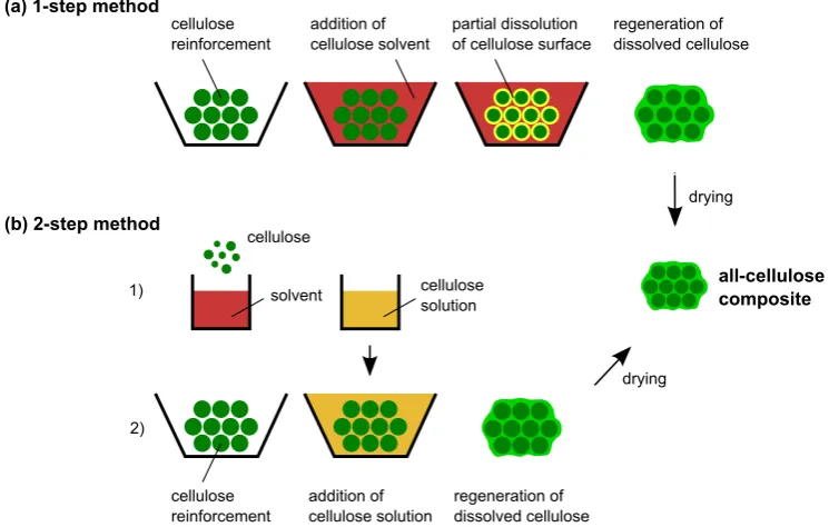
single processing step that involves wetting a cellulose reinforcement with a solvent and partially dissolving the cellulose. Regeneration of the dissolved portion of cellulose leads to the in situ formation of a matrix phase that binds together the undissolved portion of cellulose.Gindl and Keckes[2005] were the first to report the use of the 1-step method for creating an ACC, and it has been variously referred to as partial dissolution [Huber et al., 2012a], surface-selective dissolution [Soykeabkaew et al., 2008] and natural fibre welding [Haverhals et al., 2010]. It is important to note that the pro-cessing of ACCsviathe 1-step method follows a transforming instead of an adding concept. Partial dissolution transforms the outermost part of cellu-lose fibre into the matrix, instead of adding a separate matrix.
An advantage of the 1-step method is the relatively high volume fraction of fibres that can be achieved, e.g.688 vol.% are reported bySoykeabkaew et al.[2009a]. Thus, the volume fraction of fibres in an ACC approaches the theoretical maximum of 90.7 % that exists for a hexagonal packing arrange-ment. Maximising the volume fraction of fibres and minimising that of the matrix is desirable as it leads to improved mechanical properties [Hull and Clyne,1996].
1.1.3.2 Derivatised all-cellulose composites
(a) 1-step method cellulose reinforcement addition of cellulose solvent partial dissolution of cellulose surface
regeneration of dissolved cellulose
drying
all-cellulose composite (b) 2-step method
[image:35.595.111.484.114.351.2]1) 2) cellulose solvent cellulose solution cellulose reinforcement addition of cellulose solution regeneration of dissolved cellulose drying
Figure 2: Processing of ACCsvia (a) the 1-step method and (b) the 2-step method (Adapted fromHuber et al.,2012c).
costs cannot be justified by their mechanical properties, as tensile strength and Young’s modulus are inferior when compared to non-derivatised ACCs [Huber et al.,2012b]. The relatively low mechanical properties are probably due to a comparably low volume fraction of fibres (30 to 40 %) and incom-plete impregnation of the fibres due to the high viscosity of the benzylated cellulose matrix [Lu et al.,2002].
1.1.3.3 Cellulose reinforcements in all-cellulose composites
2008;Soykeabkaew et al., 2008] and flax [Gindl-Altmutter et al.,2012], and regenerated cellulose fibre including Lyocell [Gindl-Altmutter et al., 2012], Cordenka [Huber et al.,2012d,a] and Bocell [Soykeabkaew et al.,2009a].
1.1.3.4 Solvents used for processing all-cellulose composites
A solvent for industrial scale manufacture of ACCs ideally facilitates cel-lulose dissolution without pretreatment in a short time, while having a low environmental impact and being cost efficient. In the majority of stud-ies, ACCs were processed using the lithium chloride/dimethyl acetamide (LiCl/DMAc) solvent system [Nishino et al., 2004; Gindl and Keckes, 2005; Duchemin et al., 2007, 2009b; Qin et al., 2008; Soykeabkaew et al., 2008; Pullawan et al., 2013; Yousefi et al., 2013]. LiCl/DMAc is a direct solvent of cellulose with very low chain degradation during dissolution and solubil-ity of 15 wt.% [Liebert,2009;Olsson and Wesman,2013]. However, cellulose needs to be activated in a polar medium for 6 to 24 h and dissolution times of 2 to 6 h are necessary for processing fibres to ACCs by partial dissolu-tion [Qin et al.,2008;Soykeabkaew et al.,2008]. These long processing times make LiCl/DMAc less attractive.
N-methyl-morpholine-N-oxide (NMMO) is known as a relatively environ-mentally friendly solvent used on industrial scale for regenerated cellulose fibre production (Lyocell process) [Loubinoux and Chaunis,1987;Fink et al., 2001]. However, NMMO is thermally unstable and additives are necessary to prevent dangerous exothermic side reactions during cellulose dissolution [Navard et al., 2012; Rosenau et al., 2002], and it has been hardly used for manufacturing ACCs [Ouajai and Shanks,2009].
dissolution capability of ILs have since led to their use for ACC processing in many studies. ACCs have been prepared using ILsviathe 2-step method by Zhao et al.[2009], who used rice husks as reinforcement and dissolved filter paper as cellulose matrix. Several groups have also performed 1-step processing of ACCs using ILs.Duchemin et al. [2009a] used the IL 1-butyl-3-methylimidazolium chloride (BmimCl) to prepare ACCs by partial dissol-ution of microcrystalline cellulose and filter paper. Huber et al. used the IL 1-butyl-3-methylimidazolium acetate (BmimAc) in partial dissolution ap-proaches to produce ACC laminates by compression moulding [Huber et al., 2012d] and the solvent infusion process [Huber et al., 2012a]. Haverhals et al. used the IL 1-ethyl-3-methylimidazolium acetate (EmimAc) to transform loose natural fibres (hemp and cotton) into a composite structure by partial dissolution and termed the process “natural fibre welding” [Haverhals et al., 2010,2012]. Similar approaches using IL for ACC processing have also been reported in other studies [Yousefi et al.,2011; Ma et al., 2011;Shibata et al., 2013a,b].
have only been used in few ACC studies and processing has been limited to the 2-step method. Cellulose solutions in NaOH/urea were mixed with cellulose nanocrystals [Qi et al.,2009;Wang and Chen,2011;Pullawan et al., 2014] or short ramie fibres [Yang et al., 2010] to obtain isotropic ACCs and nano-ACCs with tensile strength and Young’s modulus in the range of 120 to 140 MPa and 3 to 12 GPa, respectively, depending on the mass fraction of the reinforcement. 1-step processing of an ACC based on filter paper was per-formed byHan and Yan[2010] using the additive polyethylene glycol (PEG) in an aqueous 10 wt. % NaOH/ 1 wt. % PEG solution. However, an extensive dissolution time of 12 h was required to achieve the highest Young’s modu-lus and ultimate tensile strength of 0.8 GPa and 75 MPa, respectively [Han and Yan,2010].
1.1.3.5 Mechanical properties of all-cellulose composites and comparison to bio-based composites
The mechanical properties of ACCs can also be influenced by wet draw-ing. Stretching a regenerated, but still wet ACC leads to a preferred orient-ation of cellulose crystallites in the stretching direction [Gindl et al., 2006b; Pullawan et al.,2013]. The crystalline orientation is maintained after drying and a linearly increasing relationship of tensile strength and Young’s mod-ulus with the applied draw ratio was found. Applying a draw ratio of 1.5 leads to an increase in tensile strength from 202 to 428 MPa and Young’s modulus from 9.9 to 33.5 MPa [Gindl et al., 2006b]. Similarly, the orienta-tion of nanowhiskers within an ACC can be influenced by a magnetic field to achieve an increase in mechanical properties in a preferred direction [Li et al.,2010;Pullawan et al.,2012].
(a)
0 5 10 15 20 25 30 35 400 200 400 600 800 1000
Y oung 's modulu s in G P a
Tensile strength in MPa
(b)
0 2 4 6 8 10 12 14 16 18 200 100 200 300 400 500
Y oung 's modulu s in G P a
Tensile strength in MPa
Halonen et al., 2012 Shibata et al., 2013a,b Huber et al., 2012b Larsson et al., 2014
isotropic ACCs
isotropic biocomposites
[image:40.595.133.466.132.627.2]UD ACCs UD biocomposites
1.1.3.6 Developing industrial scale manufacturing pathways for all-cellulose composites
The majority of literature studies of ACCs have produced and character-ised films of ACCs with thicknesses in the range of 0.3 to 1 mm. However, the expansion of ACCs into different applications will likely require greater thicknesses of material. The manufacture of ACCs relies on wet processing and necessitates a washing and drying step. The removal of solvent and sub-sequent drying result in a volumetric shrinkage approximately equal to the ratio of solvent to cellulose. ACC films are typically cast from 5 to 25 vol. % cellulose and hence a shrinkage of > 75 % is to be expected, that is signific-antly higher than the shrinkage of 1 to 3 % observed during injection mould-ing of thermoplastics [Rosato and Rosato, 1995]. Furthermore, the removal of solvent from the dissolved portion of cellulose also results in differential shrinkage due to the stronger shrinkage of the regenerated matrix phase in comparison to the undissolved reinforcement [Duchemin et al., 2009b]. Differential shrinkage is problematic for two reasons: (i) internal residual stresses are generated that compromise the mechanical performance of the composite; and (ii) dimensional stability of the material is decreased follow-ing the final dryfollow-ing step (i.e. warpage occurs). Hence, it is clear that extensive experimental studies and development of predictive models of shrinkage in ACCs are still required in order to meet the requirements of the composite industry. Finally, the disposal and/or recycling of the solvent and identifica-tion of cost-effective sources of cellulose are important aspects in the context of industrial manufacturing that require further research and development.
techniques (e.g. compression moulding, resin infusion) have been explored and adapted for larger scale 1-step manufacturing of ACCs [Huber et al., 2012d,a]. A common characteristic of these processing routes is the applica-tion of pressure to consolidate the material during all stages of processing so as to manage the shrinkage and ensure dimensional stability. Conventional compression moulding of composites involves the use of a rigid double-sided mould through which pressure and heat are applied to consolidate the reinforcement and matrix materials [Mazumdar,2001]. Compression mould-ing of ACC laminates was carried out byHuber et al. [2012d]. Initially, sev-eral layers of a woven regenerated cellulose fibre textile were impregnated with an IL as the solvent, followed by stacking and compression of the layers. The application of heat and pressure (110 °C, < 2.5 MPa, 80 min) leads to par-tial dissolution of the fibres within the textile layers, resulting in the in situ formation of the matrix phase. The compression moulded ACC laminates were formed into dimensionally-stable, flat sheets with a final thickness of 2 mm, tensile strength of 70 MPa, and Young’s modulus of 2.5 GPa.
Vacuum-assisted resin transfer moulding (VARTM) is a liquid moulding process that is used to fabricate complex-shaped, high quality composite laminate parts. Typically, a woven textile preform is placed on a one-sided rigid mould that is then covered with a vacuum bag. The application of a vacuum forces resin to flow through the textile preform, while also acting to remove voids and compact the laminate stack [Mazumdar,2001;Glancey, 2010].
solvent inlet
valve textile in vacuum setup
outlet valve
adjustable pressure gauge
vacuum pump A) mould
B) laminate stack C) vacuum bag D) vacuum sealant E) hose
A B
C
D E
Figure 4: Setup of the solvent infusion process (SIP) as developed by Huber et al. [2012a].
VARTM (Figure 4).Huber et al. used the IL BmimAc for the development of SIP, where further compaction and partial dissolution of the cellulose reinforcement after infusion are then achieved using external pressure and heat. Regenerating the dissolved fibre portion leads to the formation of the matrix phase and the final ACC laminate is obtained by drying [Huber et al., 2012a].
1.2
r e s e a r c h m o t i vat i o n a n d o b j e c t i v e s
1.2.1 Motivation
Cellulose represents an ideal choice as raw material for sustainable materials, due to the combination of availability, biodegradability and high mechanical properties [Wertz et al., 2010]. The use of cellulose in bio-based composites has advanced in recent years, however, chemical incompatibility between hydrophobic polymer matrices and hydrophilic natural fibres can limit the strengthening effect of the reinforcement [Bledzki and Gassan, 1999; Faruk et al.,2012]. ACCs as single-polymer composites overcome this problem and offer a promising new approach to utilise cellulose as raw material for green composites [Nishino et al.,2004;Huber et al.,2012b].
The research conducted in the field of ACCs has concentrated on thin films, however, composites of greater thickness will be necessary to trans-fer ACCs from research on a laboratory scale to replacing petrochemical polymers in actual applications. Partial dissolution has been identified as a promising processing pathway and SIP has been introduced as an upscal-able method with high potential [Huber et al.,2012a], providing the starting point for this work.
This thesis sets out to investigate open questions in upscalable processing of ACCs via SIP, deepen the understanding of structural reorganisation of cellulose by partial dissolution and its effect on the mechanical properties of the individual fibre and matrix phases and the overall composite material.
advantage-ous for analysing the effects of processing on the structure and properties of ACC laminates, as discussed in Section 2.3.2.1.
1.2.2 Objective 1: Upscaled manufacturing and size effect in all-cellulose composite laminates
SIP has been shown to be a viable processing pathway for the fabrication of thick ACC laminates [Huber et al., 2012a]. The ability of processing ACCs with increased dimensions widens the range of potential applications. How-ever, composites are known to exhibit a size effect of decreasing strength with increasing dimension [Zweben,1994;Bažant et al.,1996;Wisnom,1999; Sutherland et al.,1999a]. Therefore, the question is raised whether the mech-anical performance of ACCs is impaired by the process of upscaling the dimension of laminates.
The first objective of this thesis is to determine whether an increase in ACC laminate thickness has an influence on their mechanical properties and investigate the underlying mechanisms of a potential size effect.
1.2.3 Objective 2: Aqueous sodium hydroxide/urea solution as alternative solvent for solvent infusion processing
of ILs on a relatively small scale makes them expensive solvents [Pinkert et al.,2009;Zhu et al.,2006]. In contrast to their image as green solvents due to their low volatility, the toxicity of imidazolium-based ILs has been docu-mented [Ranke et al.,2004;Bernot et al.,2005;Zhao et al.,2007;Jastorff et al., 2005;Matzke et al.,2007], and is a potential environmental issue when pro-cessing ACCs on a larger scale and suggests the use of alternative solvents.
An aqueous solution of 7 wt.% NaOH/12 wt.% urea (NaOH/urea) ap-pears promising for industrial scale manufacture of ACCs due to its low environmental impact, low cost, no necessary pretreatment of the cellulose and short dissolution times of 2 to 5 min [Cai and Zhang, 2005; Qi et al., 2008a]. In the field of ACCs, NaOH/urea solvents have been limited to com-posite processing via the 2-step method by preparing a fully dissolved cel-lulose solution that is combined with celcel-lulose nanocrystals [Qi et al.,2009; Wang and Chen,2011;Pullawan et al.,2014] or short ramie fibres [Yang et al., 2010].
Using NaOH/urea for upscaled manufacturing presents challenges due to the limited cellulose solubility of 5 to 7 wt. % and subambient temperatures (-12.5 °C) required for dissolution [Cai and Zhang,2005;Jin et al.,2007;Egal et al.,2008]. Consequently, the second objective of this thesis is to determine whether an aqueous NaOH/urea solution can be used as cellulose solvent for processing ACC laminatesviaSIP.
1.2.4 Objective 3: Removal of solvent from all-cellulose composite laminates
important for economical, environmental, health and safety, and engineer-ing reasons. However, regenerated cellulose films and fibres are reported to contain solvent residues after washing [Mahadeva and Kim,2012; De Silva et al.,2015].
Hence, the third objective of this thesis is to investigate whether the solvents used for partial dissolution in this work, ILs and aqueous NaOH/urea solu-tion, are completely removed by washing or remain trapped, particularly in the core of thick ACC laminates.
1.2.5 Objective 4: Individual structural and mechanical characterisation of fibre and matrix phases in all-cellulose composite laminates
2
L I T E R AT U R E R E V I E W
2.1
c e l l u l o s e
Cellulose is the structural element of plants and its molecular structure with the formula (C6H10O5)n was first described by Anselme Payen in 1838.
It is the main molecule in the cell wall of higher plants and is also pro-duced by algae, certain bacteria, protozoans and animal tunicates [Wertz et al.,2010]. With an estimated annual biomass production of approximately 1.5×10¹²tons [Klemm et al., 2005] cellulose is the most common organic polymer on earth and can be considered an almost inexhaustible raw ma-terial for environmentally friendly products. Today cellulose is mainly used in the construction, paper and textile industry, but also in pharmaceuticals, foodstuffs and cosmetics [Klemm et al.,2005].
2.1.1 Molecular structure
Figure 5: Molecular structure of cellulose (adapted fromPinkert et al.,2010).
by 180 °. This results in a flat ribbonlike structure that is stabilised by in-tramolecular hydrogen bonds [Klemm et al.,2005;Wertz et al.,2010].
The degree of polymerisation (DP) of cellulose is a measure of the chain length, i.e. the number of linked AGUs. The DP varies with cellulose source and typical values are in the range of 10000 in wood; 3000 to 15000 in cotton; 6500 to 8000 in bast fibres, such as flax and ramie; up ot 10000 in bacterial cel-lulose; 300 to 700 in wood pulp; and 150 to 300 in powdery microcrystalline cellulose [Klemm et al.,2005;Keijsers et al.,2013].
Typical properties of cellulose, such as hydrophilicity, biodegradability, chirality and broad chemical reactivity due to the manifold hydroxyl groups (3 per AGU), are based on the molecular structure. The hydroxyl groups are also the basis for an extensive hydrogen bond network, leading to sev-eral crystalline arrangements and semicrystalline structures [Klemm et al., 2005].
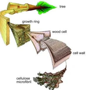
com-Figure 6: Hierarchical structure of cellulose from microfibril to tree (Image credit: Mark Harrington, University of Canterbury).
plex natural composite. The orientation of the cellulose fibrils, referred to as the microfibril angle, varies greatly in the different cell wall layers, e.g. from 2 to 20 ° and 85 to 90 ° in alternating lamellae of bamboo cell wall [ Para-meswaran and Liese,1976]. The microfibrils can be found in bundles, e.g. in wood and bast fibres such as hemp and flax, or as individual fibres, e.g. in cotton [Klemm et al.,2005;Wertz et al.,2010].
2.1.2 Secondary structure
[image:52.595.154.449.112.421.2]Perfectly crystalline
Paracrystalline Amorphous with correlation
Fully amorphous
Figure 7: Schematic of cellulose chains (hypothetically) arranged in different de-grees of order, from perfectly crystalline to fully amorphous (adapted fromHowsmon and Sisson,1954).
can range from low, referred to as amorphous, to dense and regular, re-ferred to as crystalline (Figure 7). Due to the mixture of low and highly ordered domains, cellulose is regarded as a semicrystalline polymer and its fine structure has been investigated for almost a century [Herzog et al.,1923; Staudinger,1930;Ingersoll,1946].
Figure 8: Models for the supermolecular structure of (a) crystalline and
(b & c) semicrystalline cellulose (Fink et al.,1995; reproduced with kind permission of Springer Science and Business Media).
2.1.3 Crystal structure and polymorphy
The crystal structure of cellulose has been extensively studied by nuclear magnetic resonance, infrared and diffraction methods and seven polymorphs of cellulose are known (Iα, Iβ, II, IIII, IIIII, IVI and IVII,), which can be
inter-converted (Figure 9, O’Sullivan, 1997). Cellulose I is the native and most studied form and it was found that it presents a mixture of two polymorphs, Iα and Iβ, of which Iα is triclinic and metastable and can be converted to the monoclinic Iβby annealing at 260 ° in dilute alkali solution [VanderHart
and Atalla,1984;Sugiyama et al.,1991]. Cellulose I is irreversibly converted to cellulose II by (i) dissolution and regeneration or (ii) mercerisation (swell-ing in concentrated NaOH solution). Cellulose IIII and IIIII are obtained by
Cellulose I
Cellulose IIII
Cellulose IVI
Cellulose IIIII
Cellulose IVII Cellulose II
Regeneration Mercerisation
ammonia treatment
heating to 206 C in glycerol
° heating to 206 C
in glycerol ° ammonia treatment
Figure 9: Interconversion of cellulose polymorphs (adapted fromO’Sullivan,1997).
Heating cellulose IIII or IIIIIin glycerol to 206 °C results in the conversion to
cellulose IVI and IVII, respectively [O’Sullivan,1997].
The conversion of cellulose I to cellulose II changes the chain packing arrangement and hydrogen bonding pattern. During mercerisation or dis-solution and regeneration the parallel chains of cellulose I rearrange to the more stable antiparallel packing of cellulose II [Kolpak and Blackwell,1976]. An interdiffusion model for this change was proposed byOkano and Sarko [1985], where neighbouring mirofibrils (each of parallel packed cellulose I) of opposite orientation take up NaOH solution and are turned into intermedi-ate Na-cellulose. Mobilisation of chains allows their interdiffusion, such that upon washing and drying microfibrils of antiparallel packing are present [Zugenmaier,2008].
OH(2)-Cellulose I Cellulose II
Figure 10: Hydrogen bonding pattern of cellulose I and cellulose II (adapted from O’Sullivan,1997).
O(2) between corner and centre chains, which is not present in cellulose I [O’Sullivan,1997].
2.1.4 Amorphous cellulose
The amorphous domains between crystallites are characterised by a relat-ively low order in their arrangement, however, the wide variability of order between fully amorphous and perfectly crystalline (Figure 7) impedes a clear definition of amorphous cellulose, as even the non-crystalline parts exhibit a certain degree of order. Relatively crystalline cellulose can be turned into true amorphous cellulose by ball-milling, grinding, saponification or regen-eration with ethanol from solution in SO2-diethylamine-dimethylsulfoxide
the OH(2) and OH(3) hydroxyl groups are involved in intermolecular hy-drogen bonding, while OH(6) forms an intrachain hyhy-drogen bond. It is con-cluded that amorphous cellulose consists of randomly coiled chains with local domains of higher order held together by intermolecular hydrogen bonding [Kondo and Sawatari,1996].
Interestingly, amorphous cellulose can recrystallise. Moisture induces plas-ticisation and allows recrystallisation of fully amorphous cellulose into a cel-lulose II lattice, while the presence of nuclei in partially crystalline celcel-lulose is necessary to restructure into a cellulose I lattice [Bhama Iyer et al.,1984].
2.1.5 Crystallinity
2.2
c e l l u l o s e d i s s o l u t i o n
Many cellulose applications necessitate reshaping of cellulose to e.g. fibres, films or membranes, however, in contrast to thermoplastics cellulose decom-poses at elevated temperatures. Therefore, dissolution is the main processing route of cellulose. Dissolution of cellulose is challenging, it is insoluble in wa-ter and common organic solvents and can only be dissolved by a selection of solvents [Navard et al.,2012; Olsson and Wesman,2013]. The general train of thought is that breaking the inter- and intramolecular hydrogen bonding network is the key for dissolving cellulose [Zhang et al., 2002; Chen et al., 2007;Jin et al.,2007;Qi et al.,2011;Navard et al.,2012].
Lindman et al. [2010] have critically questioned the importance of hydro-gen bonding and suggest that van der Waals forces and hydrophobic in-teractions are elementary to cellulose solubility, as well. The importance of the amphiphilic character of cellulose and hydrophobic interactions between cellulose sheets has been highlighted and discussed in several recent articles [Medronho et al.,2012;Medronho and Lindman,2014b,a;Alves et al.,2015].
The specific mechanisms for dissolution of cellulose in the solvents used in this study, aqueous NaOH/urea solution and ionic liquids, are given in detail in Sections2.2.3and2.2.4, respectively.
2.2.1 Derivatising cellulose solvents