http://www.scirp.org/journal/msce ISSN Online: 2327-6053
ISSN Print: 2327-6045
DOI: 10.4236/msce.2019.73006 Mar. 29, 2019 65 Journal of Materials Science and Chemical Engineering
Characteristics of Absorption Equilibrium with
HFC-134a and an Ionic Liquid Pair
Takehiro Esaki
1*, Noriyuki Kobayashi
2, Hiroki Uchiyama
1, Yousuke Matsukuma
11Department of Chemical Engineering, Faculty of Engineering, Fukuoka University, Fukuoka, Japan
2Department of Chemical Systems Engineering, Graduate School of Engineering, Nagoya University, Fukuoka, Japan
Abstract
Cold energy generation systems must be improved to prevent catastrophic climate change. In this study, we focused on an absorption chiller cycle with HFC-134a and an ionic liquid pair as the refrigerant and absorbent, respec-tively. It was expected that this absorption chiller cycle could generate cold heat below 0˚C. Two liquids were selected and their absorption equilibrium with this pair was evaluated for the absorption chiller cycle. We measured the adsorbed amount at equilibrium with 1-butyl-3-methylimidazolium
bis(trifluoromethanesulfonyl)imide [BMIM][Tf2N] and
N-trimethyl-N-butylammonium bis(trifluoromethanesulfonyl)imide
[N1113][Tf2N]. The experimental results were reproduced using the non- random two liquid (NRTL) model. This analysis model corresponded well in terms of the amount of adsorption at equilibrium with the experimental re-sults. A Duhring diagram was also generated the NRTL model, and the ab-sorption cycle characteristics as a function of temperature were determined. The absorption chiller cycle obtained cold heat at 10˚C with a regeneration temperature of 70˚C in addition to generating cold heat below 0˚C.
Keywords
Absorption Chiller Cycle, HFC-134a, Ionic Liquid, Duhring Diagram
1. Introduction
Improved efficiency of heat management systems is important for building of a sustainable society. Recently, cold heat energy has seen increasing demand for cooling and frizzing sections in industrial processes. In residential construction, cold energy for air conditioning in the summer is required on a large scale, which only continues to increase [1]. Therefore, it reducing energy consumption
How to cite this paper: Esaki, T., Ko-bayashi, N., Uchiyama, H. and Matsukuma, Y. (2019) Characteristics of Absorption Equilibrium with HFC-134a and an Ionic Liquid Pair. Journal of Materials Science and Chemical Engineering, 7, 65-78. https://doi.org/10.4236/msce.2019.73006
Received: September 12, 2018 Accepted: March 26, 2019 Published: March 29, 2019
Copyright © 2019 by author(s) and Scientific Research Publishing Inc. This work is licensed under the Creative Commons Attribution International License (CC BY 4.0).
DOI: 10.4236/msce.2019.73006 66 Journal of Materials Science and Chemical Engineering
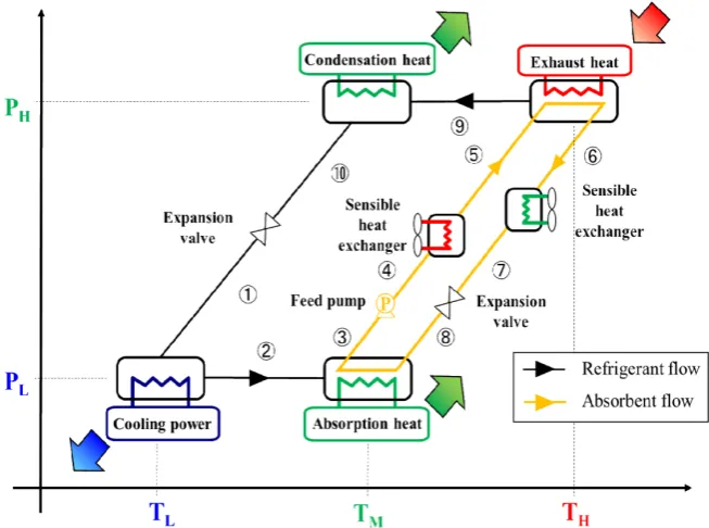
for the generation cold energy must be met by developing novel technologies. Recently, it has been suggested that the heat-driven chiller and refrigerator could be operated by the heat output of cogeneration, exhausting heat from industrial processes, or solar heat collect systems. As these chillers and refrigerators are commercialized with improved energy efficiency, energy consumption can be reduced for the generation of cold energy. Particularly, absorption chillers fea-ture efficient heat utilization and Figure 1 shows a schematic of absorption chiller operation. Absorption chillers consist of an evaporator, absorber, gene-rator and condenser. The refrigerant vapor from the evapogene-rator is evaporated and introduced into the absorber. The refrigerant vapor is then absorbed in the absorbent and afterwards is moved to the generator while heating. The heat causes the refrigerant gas to be desorbed from the absorbent and condensed in the condenser. The exhaust heat is used as the heat source of the generator. The most common refrigerant/absorbent pairs for absorption chillers are H2O/LiBr
aqueous solution [2] and NH3/H2O systems.
Absorption chillers with H2O/LiBr aqueous solution systems have been
com-mercialized and installed as part of building air conditioners. Absorption chillers with NH3/H2O systems are typically used as refrigerators for industrial processes.
Although absorption chillers and refrigerator driven heat sources can reduce energy consumption, problems remain in terms of their operation and ability. Absorption chillers with the H2O/LiBr cannot generate cold heat below freezing
temperature and the start-up time long time due to the influence of crystalliza-tion [3]. Although absorption refrigerator with NH3/H2O can generate cold heat
[image:2.595.209.536.461.704.2]below freezing, the volume of absorption refrigerator required is very large. Thus, flash towers were introduced to ameliorate the problems with the
DOI: 10.4236/msce.2019.73006 67 Journal of Materials Science and Chemical Engineering
NH3/H2O pair in addition to the refrigerator itself. The material utilized for
re-frigeration is also limited by the corrosive effects of ammonia dissolved in water. In this study, we evaluated an absorption chiller with a novel refrigerant/absorbent pair, HFC-134a and ionic liquid. A mechanical type refrigerator was utilized with HFC-134a as the refrigerant.
The ionic liquid consisted of an anion and a cation [4]. Ionic liquids have unique characteristics including very low vapor pressure and wide liquidus range. If an absorption chiller could be operated with an HFC-134a/ionic liquid pair, it could generate cold heat below 0˚C without the need for a flash tower. As the HFC-134a is used as the refrigerant of the mechanical chiller, it is expected to combine with this absorption chiller and mechanical refrigerator.
In this study, 1-butyl-3-methylimidazolium
bis(trifluoromethanesulfonyl)imide [BMIM][Tf2N] and
N-trimethyl-N-butylammonium bis(trifluoromethanesulfonyl)imide
[N1114][Tf2N] were used as ionic liquid adsorbents and their absorption cha-racteristics in the absorption chiller cycle were evaluated. The dependence of the absorption equilibrium on temperature and pressure with these ionic liquids was also determined along with absorption model correlations with the NRTL model and chiller cycle characteristics using Duhring diagrams.
2. Experimental Procedure
[image:3.595.268.475.452.693.2]2.1. Experimental Apparatus
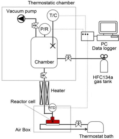
Figure 2 shows the experimental apparatus used to measure the amount of ab-sorption via the volumetric method. This apparatus consisted of an HFC-134a
DOI: 10.4236/msce.2019.73006 68 Journal of Materials Science and Chemical Engineering
gas tank, chamber, reactor cell, pressure sensors, and thermocouples. The appa-ratus was enclosed in a thermostatic box with a chamber volume of 0.74 × 10⁻³ m3
and reactor cell volume of 0.16 × 10⁻⁴ m3. The reactor cell was a flange
(Cosmo-tec corporation, NW50BK) composed of stainless steel. The chamber was equipped with two pressure sensors (SHVG-500KP, Keller corporation, AP-C33, Keyence Japan) which could measure minute pressure changes associated with the absorption by PC. The pressure sensor was selected depending on the meas-ured HFC-134a pressure range. The reaction cell was connected to the heat-ing/cooling system by a thermostat bath and the sample was placed in the reac-tion cell and measured using Pt resistance temperature sensors.
2.2. Refrigerant and Absorbent
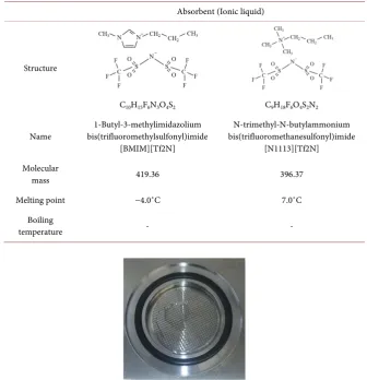
[image:4.595.204.541.358.707.2]The refrigerant used was HFC-134a (1,1,1,2-tetrafluoroethane) with a purity of >99.7%. The [BMIM][Tf2N] and [N1114][Tf2N] adsorbents were obtained from Wako and Sigma Aldrich Japan, respectively. These absorbents were dried at 343 K for 2 hr under vacuum and their structures. The property of absorbents is shown in Table 1. Figure 3 shows a photograph of the absorbent in the reactor.
Table 1. Properties of the absorbents used in this study.
Absorbent (Ionic liquid)
Structure
C10H15F6N3O4S2 C9H18F6O4S2N2
Name bis(trifluoromethylsulfonyl)imide 1-Butyl-3-methylimidazolium [BMIM][Tf2N]
N-trimethyl-N-butylammonium bis(trifluoromethanesulfonyl)imide
[N1113][Tf2N] Molecular
mass 419.36 396.37
Melting point −4.0˚C 7.0˚C
Boiling
temperature - -
DOI: 10.4236/msce.2019.73006 69 Journal of Materials Science and Chemical Engineering
The amount of absorbent used was 2.0 g.
2.3. Experimental Procedure
The reactor cell containing the absorbent was connected to the chamber. The experimental equipment was first degassed at 1 kPa. To obtain the desired pres-sure, HFC-134a refrigerant gas was introduced into the chamber and the ther-mostat bath was set to the desired temperature. Operations involved operating the valves and connecting the reaction cell and the chamber. During absorption, the chamber pressure dropped and was recorded using a PC. When the chamber pressure change reached equilibrium, the amount of HFC-134a used in the ab-sorption was calculated from the pressure change value. The Peng-Robinson equation was used to calculate the weight of the absorbed HFC-134a, and can be expressed as follows:
(
)
{
}
22 2
1 1
2
c
g a m T T
R T P
v b v bv b
+ −
= −
− + − (1)
The absorption extent was calculated as follows:
(
)
{
}
(
)
{
}
2
initial equilibrium 2 2
chamber chamber chamber
2
2 2 2
equiribrium equiribrium equiribrium
1 1 2 1 1 2 c g c g
a m T T
R T
P P
v b v bv b
a m T T
R T
v b v bv b
+ − − = − − + − + − − − − + − (2) chamber HFC-134a initial chamber V n ν
= (3)
chamber cell HFC-134a equiribrium equiribrium V n ν +
= (4)
(
HFC-134a initial HFC-134a equilibrium)
HFC-134aHFC-134a absorption
absorbent
n n M
z
W
− ⋅
= (5)
3. Results and Discussion
3.1. Pressure Change during Absorption Determined by the
Volumetric Method
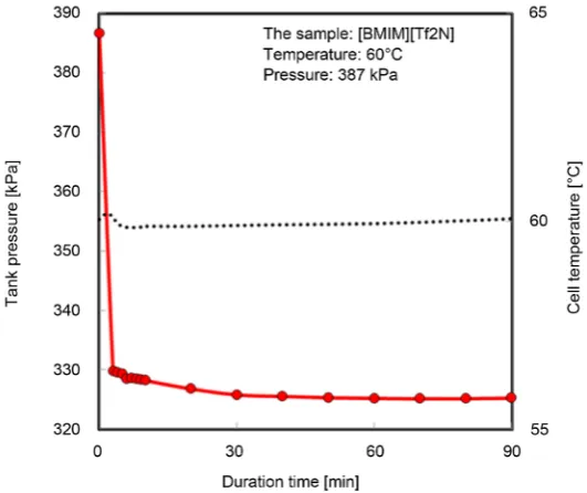
DOI: 10.4236/msce.2019.73006 70 Journal of Materials Science and Chemical Engineering Figure 4. Experimental demonstration of the chamber pressure change.
materials was calculated using the pressure changes with the Peng-Robinson equation.
3.2. Absorption Equilibrium Model
Various models for the analysis of experimental absorption of HFC-134a with ionic liquids have been suggested. In this study, the absorption data was ana-lyzed using the non-random two liquid model (NRTL) model. In general, va-por-liquid absorption equilibrium for an N-component system can be expressed by Equation (6),
(
1, ,)
s i i i i i
y pΦ =x
γ
p i= N (6)where yi and xiare the vapor phase and liquid phase mole fractions for the ith
species, respectively, P is the vapor equilibrium pressure, s i
P
is the saturatedvapor pressure for the ith species, Φi is a correction factor for the ith species,
and γi is the activity coefficient for the ith species. For the binary system (N =
2) of HFC-134a (R) and ionic liquid (IL) mixture system, the ionic liquid has little vapor pressure. Thus, it is reasonable to assume that PILS is 0 on yR = 1
at the temperatures used in this study. The activity coefficient for HFC-134a can be described by Equation (7):
R
R S
R R
P x P
γ = Φ (7)
In addition, the correction factor, ΦR, for the present case is [5]:
(
)(
)
exp
L s
R R R
R
g
B V P P
R T
− −
Φ =
(8)
us-DOI: 10.4236/msce.2019.73006 71 Journal of Materials Science and Chemical Engineering
ing an equation of state program [6] and the molar volume, L R
V
, can becal-culated if T is less than the critical temperature, Tc, of pure HFC-134a.
Previously, VR was suggested and defined by Equation (9)
(
)
01
R V R
V = −α V (9)
where 0 R
V
is the molar liquid volume of the ionic liquid at temperature Tand αV is a unique temperature-independent constant. Here we assumed that αV = 0.594 [7]. For the isothermal solubility data, the activity coefficients, γR,
were calculated at each observed xR point. Several activity models are available
in the literature [8]. In the NRTL model, γR and γIL are calculated and defined
by Equations (10) and (11)
(
)
2
2 21 12 12
21 2
21 12
R IL
R IL IL R
G G
x
x x G x x G
τ
γ = τ + +
+
(10)
(
)
2
2 12 21 21
12 2
12 21
IL R
IL R R IL
G G
x
x x G x x G
τ
γ = τ + +
+
(11)
where G12 and G21 are defined by the NRTL interaction parameters as
de-scribed by Equations (12) and (13).
(
)
12
exp
12G
=
−
ατ
(12)(
)
21
exp
21G
=
−
ατ
(13)where α is the independent unique parameter, assumed to be α = 0.2 [9], and
τ12 and τ21 are adjustable binary interaction parameters using only the
tem-perature dependent terms ( 0 12
τ
, 0 21τ
, 1 12τ
, 1 21τ
). We modeled the parametersas shown in Equations (14) and (15).
0 1
12 12 12
T
τ
=
τ
+
τ
(14)0 1
21 21 21
T
τ
=
τ
+
τ
(15)3.3. Absorption Extent at Equilibrium
DOI: 10.4236/msce.2019.73006 72 Journal of Materials Science and Chemical Engineering Table 2. The amount of absorption at equilibrium with [BMIM][Tf2N] and [N1113][Tf2N] under various experimental conditions.
[BMIM][Tf2N] [N1113][Tf2N]
T [˚C] P [kPa] x[ g−R/g−IL] T [˚C] P [kPa] x [g−R/g−IL]
30
302.4 0.108
40
104.3 0.013
448.5 0.229 319.3 0.085
596.5 0.424 465.2 0.166
40
294.3 0.054 605.0 0.255
491.0 0.153
50
304.5 0.060
638.2 0.277 473.8 0.101
50
304.9 0.044 597.7 0.145
467.9 0.094 779.0 0.243
627.4 0.1658
60
310.2 0.042
781.6 0.2513 597.4 0.112
60
303.3 0.037 790.7 0.184
460.5 0.065 998.0 0.278
596.0 0.097
70
301.2 0.022
770.2 0.155 442.0 0.043
70
453.0 0.051 802.8 0.123
804.4 0.124 999.0 0.173
961.9 0.169
80
304.4 0.080
80
483.4 0.041 675.9 0.251
597.8 0.070 1002.4 0.326
974.4 0.131
90
475.4 0.053
90 785.9 0.071 775.4 0.076
[image:8.595.210.538.99.475.2]1006.7 0.101 993.3 0.090
Table 3. NRTL model parameters for [BMIM][Tf2N], [N1113][Tf2N], and [BMIM][PF6] [9]. 0 12 τ 0 21 τ 1 12 τ 1 21 τ
[BMIM][Tf2N] −1.550 809.5 0 0
[N1113][Tf2N] 1.24 × 10⁻⁶ 256.5 4.35 × 10⁻⁷ 0.86 × 10⁻³
[BMIM][PF6] −3.001 1699.2 2.51 −1000
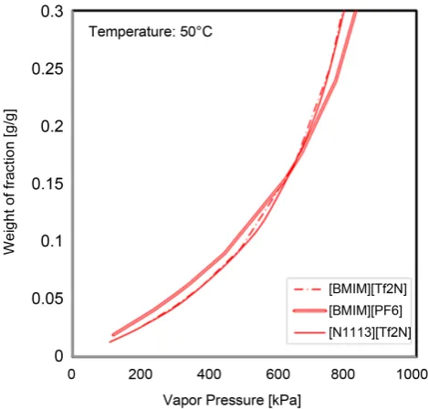
the experimental pressure, strongly influenced the experimental error value. Different ionic liquids were prepared to evaluate the effects of ion structure on absorption equilibrium. Figure 8 shows the amount of absorption at equilibrium at 50˚C with three ionic liquids. The [BMIM][Tf2N] and [N1113][Tf2N] data was obtained from this study, and that of [BMIM][PF6] was from the literature
[9]. Figure 8 shows that the amount of absorption at equilibrium was equivalent for all three ionic liquids.
[image:8.595.207.541.524.590.2]DOI: 10.4236/msce.2019.73006 73 Journal of Materials Science and Chemical Engineering Figure 5. Representative temperature variation of the weight
fraction for different HFC-134a pressures with [BMIM][Tf2N].
Figure 6. Representative temperature variation of the weight fraction for different HFC-134a pressure with [N1113][Tf2N].
obtained in the analysis using the Clausius-Clapeyron equation, as described by Equation (16):
1
2 2 1
1 1
ln ab
g H P
P R T T
= −∆ −
(16)
[image:9.595.253.486.72.286.2] [image:9.595.253.488.332.550.2]DOI: 10.4236/msce.2019.73006 74 Journal of Materials Science and Chemical Engineering Figure 7. Comparison between the measured and predicted
va-por pressures of the refrigerants in the ionic liquid mixture using the NRTL model.
Figure 8. Representative absorbent variation for the weight frac-tion for different HFC-134a pressures with the NRTL model.
each temperature.
3.4. Some Common Mistakes
[image:10.595.255.490.348.572.2]DOI: 10.4236/msce.2019.73006 75 Journal of Materials Science and Chemical Engineering
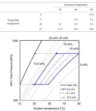
[image:11.595.215.527.336.695.2]lists the concentration weight of fraction at each temperature and pressure. As the evaporator temperature decreased, the concentration of adsorbent also de-creased. Figure 9 shows the Duhring diagram for [BMIM][Tf2N] which was used to evaluate the effect of regeneration temperature on the absorption weight fraction. The evaporator, absorber, and condenser were set to 10˚C, 30˚C, and 30˚C, respectively. The absorption weight was 13.9 wt% on the evaporator and absorber under these temperature conditions. The weight of desorption was 6.8, 8.1, and 10.2 wt% at 90˚C, 80˚C, and 70˚C, respectively. A significant difference in the absorption and desorption weights could be obtained under these temper-ature conditions. The absorption chiller could be operated with highest efficien-cy at 70˚C and Figure 10 shows the effect of the evaporator set to 10˚C, 5˚C, and 0˚C, with the generation temperature set to 90˚C. From Figure 10, an effective absorption chiller cycle was obtained with freezing heat at the evaporator at 0˚C, but the difference between absorption and desorption weight fraction was mi-nimal. It is likely that a large volume of absorbent must be circulated to obtain significant amounts of freezing heat compared to other temperature conditions.
Table 4. Lists the concentration weight of fraction at each temperature and pressure. Generator temperature
70 80 90
Evaporator temperature
0 - - 0.33
5 - 1.6 3.1
10 3.7 5.7 7.1
15 11.2 13.2 14.5
Figure 9. The Duhring diagram of HFC-134a and [BMIM][Tf2N] for
DOI: 10.4236/msce.2019.73006 76 Journal of Materials Science and Chemical Engineering Figure 10. The Duhring diagram of HFC-134a and [BMIM][Tf2N] for
different evaporator temperatures.
4. Conclusions
In this study, absorption chiller cycle characteristics were evaluated for a novel refrigerant and absorbent. HFC-134a was selected as a refrigerant and
1-butyl-3-methylimidazolium bis(trifluoromethanesulfonyl)imide [BMIM][Tf2N] and N-trimethyl-N-butylammonium
bis(trifluoromethanesulfonyl)imide [N1113][Tf2N] as absorbents. The major conclusions can be summarized as follows:
1) The amount of absorption at equilibrium of the [BMIM][Tf2N] and [N1113][Tf2N] systems was measured using the volumetric method. The amount of absorption at equilibrium was affected by absorption temperature and HFC-134a pressure. The experimental results could be accurately repro-duced by the NRTL model using suitable NRTL model parameters.
2) Duhring diagrams were generated for the HFC-134a and [BMIM][Tf2N] pair. Freezing cold heat could be successfully generated at a regeneration tem-perature of 90˚C.
Conflicts of Interest
The authors declare no conflicts of interest regarding the publication of this pa-per.
References
[1] U.S. Energy Information Administration (2017) International Energy Outlook.
https://www.eia.gov/outlooks/ieo/
DOI: 10.4236/msce.2019.73006 77 Journal of Materials Science and Chemical Engineering Absorption Chiller. International Journal of Refrigeration, 92, 1-9.
https://doi.org/10.1016/j.ijrefrig.2018.05.007
[3] Ihtsham-ul-Haq Gilani, S. and Ahmed, M.S.M.S. (2015) Crystallization Detection for Double-Effect LiBr-H2O Steam Absorption Chiller. Energy Procedia, 75,
1522-1528.https://doi.org/10.1016/j.egypro.2015.07.304
[4] Minea, A.A. and Murshed, S.M.S. (2018) A Review on Development of Ionic Liquid Based Nanofluids and Their Heat Transfer Behavior. Renewable and Sustainable Energy Reviews,91, 584-599.https://doi.org/10.1016/j.rser.2018.04.021
[5] Dong, L., Zheng, D.X. and Wu, X.H. (2012) Working Pair Selection of Compression and Absorption Hybrid Cycles through Predicting the Activity Coefficients of Hy-drofluorocarbon + Ionic Liquid Systems by the UNIFAC Model. Industrial & Che-mistry Research, 51, 4741-4747.ttps://doi.org/10.1021/ie202029d
[6] Yokozeki, A., Sato, H. and Watanabe, K. (1997) Ideal-Gas Heat Capacities and Viri-al Coefficients of HFC Refrigerants. International Journal of Thermophysics, 19, 89-127.https://doi.org/10.1023/a:1021499018749
[7] Shiflett, M.B. and Yokozeki, A. (2006) Solubility and Diffusivity of Hydrofluoro-carbons in Room-Temperature Ionic Liquids. AIChE Journal, 52, 1205-1219. https://doi.org/10.1002/aic.10685
[8] Walas, S.M. (1985) Phase Equilibria in Chemical Engineering. Butterworth, Boston. [9] Shiflett, M.B., Harmer, M.A., Junk, C.P. and Yokozeki, A. (2006) Solubility and
DOI: 10.4236/msce.2019.73006 78 Journal of Materials Science and Chemical Engineering
Nomenclature
Nomenclature Subscripts
P Pressure [kPa] initial initial
Rg Gas constant [J·mol−1·˚C−1] equilibrium equilibrium ν Molar volume [m3·mol−1] chamber chamber
ΔHab Absorption heat [kJ·mol−1] cell reactor dell T Temperature [˚C] absorption absorption
TC Critical temperature [˚C] HFC-134a HFC-134a z Weight of fraction [g-refrigerant/g-absorbent] absorbent absorbent n Molar quantity [mol] R refrigerant
M Molecular weight [kg·mol−1] IL ionic liquid W Weight [g]
V Volume [m3]
Φ Correction factor [-]
γ Activity coefficient [-]
s i
P
Saturated vapor pressure [kPa] B 2nd virial coefficient [m3·mol−1]α Unique temperature-independent constant [-]
y Vapor phase mole fraction [-]
x Liquid phase mole fraction [-]
τ, G NRTL model parameters [-]
a, b, m Peng-Robinson equation parameters [-]
L R
![Table 3. NRTL model parameters for [BMIM][Tf2N], [N1113][Tf2N], and [BMIM][PF6] [9].](https://thumb-us.123doks.com/thumbv2/123dok_us/9081106.404815/8.595.210.538.99.475/table-nrtl-model-parameters-bmim-tf-tf-bmim.webp)
![Figure 5. Representative temperature variation of the weight fraction for different HFC-134a pressures with [BMIM][Tf2N]](https://thumb-us.123doks.com/thumbv2/123dok_us/9081106.404815/9.595.253.488.332.550/figure-representative-temperature-variation-weight-fraction-different-pressures.webp)
![Figure 10. The Duhring diagram of HFC-134a and [BMIM][Tf2N] for different evaporator temperatures](https://thumb-us.123doks.com/thumbv2/123dok_us/9081106.404815/12.595.247.503.71.317/figure-duhring-diagram-hfc-bmim-different-evaporator-temperatures.webp)
