Procedia Environmental Sciences 22 ( 2014 ) 120 – 130
1878-0296 © 2014 The Authors. Published by Elsevier B.V. This is an open access article under the CC BY-NC-ND license (http://creativecommons.org/licenses/by-nc-nd/3.0/).
Peer-review under responsibility of the Eindhoven University of Technology, Faculty of the Built Environment, Urban Planning Group
doi: 10.1016/j.proenv.2014.11.012
Available online at www.sciencedirect.com
ScienceDirect
12th International Conference on Design and Decision Support Systems in Architecture and Urban
Planning, DDSS 2014
Integrating rapid 3D data collection techniques to support BIM
design decision making
Richard Laing
a*, Marianthi Leon
a, Lamine Mahdjoubi
b, Jonathan Scott
aaRobert Gordon University, The Scott Sutherland School of Architecture and Built Environment, Garthdee Road, Aberdeen, AB10 7QE, UK bUniversity of the West of England, Department of Architecture and the Built Environment, Bristol, UK
Abstract
In recent years, there have been rapid developments in techniques available to capture three dimensional data with regards to the existing built environment. Such technologies support the collection of both large scale landscape and streetscape data, as well as information pertaining to building details such as sculpture and decorative features. During the past five years, there has also been a similar development in the software technologies available to support building information modelling (BIM). Whilst the emphasis in terms of initial introduction of BIM has been predominantly within the construction phase of new developments, there is clear potential to incorporate 3D data pertaining to the existing environment, with apparent value in terms of both the conceptual design phase and during detailed consideration of spatial layout and environmental analysis. This paper describes the processes involved in incorporating on-site collected 3D data within BIM, including modelling and analysis processes.
© 2014 The Authors. Published by Elsevier B.V.
Peer-review under responsibility of the Eindhoven University of Technology, Faculty of the Built Environment, Urban Planning Group.
Keywords: BIM; scanning; photogrammetry; design; evaluation
* Corresponding author. Tel.: +44-1224-263716; fax: +44-1224-263777.
E-mail address: [email protected]
© 2014 The Authors. Published by Elsevier B.V This is an open access article under the CC BY-NC-ND license (http://creativecommons.org/licenses/by-nc-nd/3.0/).
1.Introduction
Several 3D data collection techniques have emerged recently, including scanning, photogrammetry, virtual modelling, 3D printing and rapid prototyping to capture information about existing buildings and environments. Together, these support BIM-enabled design decision-making. However, there is currently a lack of evidence regarding the most effective technique for integrating rapid 3D data collection with BIM for design evaluation and analysis. The primary strength of object oriented BIM models is that they are able to incorporate detailed and layered information pertaining to the environment represented. A practical challenge facing the design team working either with an existing building or within a site context which effects existing buildings, is that of how to include accurate data reflecting the pre-existing environment. This paper examines a critical analysis of a range of rapid data collection techniques, namely high definition 3D scanning and cloud-based photogrammetry, with particular reference to the incorporation of outputs within BIM environments. The paper then discusses how such data can be used to support design decision making, with particular emphasis on use within building performance and facilities management during the life cycle.
2.3D data collection techniques
The methods considered in the research for rapid collection of data concern material surface information. That is, the collection of photographic and geometric information concerning visible material surfaces. Within architectural design and urban planning, there is likely to be the potential to apply methods which collect both large scale spatial information, and also methods which help to collect detailed building specific information. The choice of method for a particular project is likely to be affected by access to equipment, cost, time and expertise.
Which regards to the collection of larger scale spatial data, the availability and speed of high definition 3D scanning technology has improved greatly in recent years, albeit without a comparable improvement in cost. 3D scanning allows the rapid collection of highly detailed ‘point clouds’, which represent the surface characteristics of objects visible to the scanner head. Figure 1 illustrates a typical 3D scanner (Leica C10), which is sufficiently portable to be used in the field, and away from point and data connections for many hours.
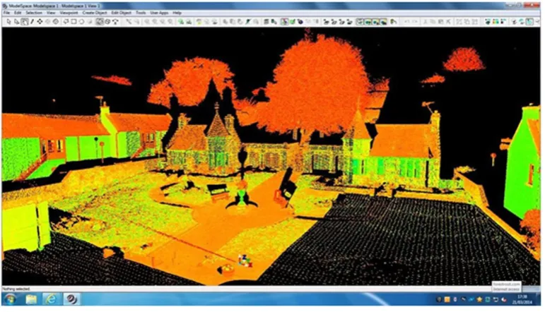
Scanners operate using lasers to collect many millions of ‘points’ of data, over a period of 20-40 minutes. A single scan can cover ranges of up to approximately 200 metres, and the resultant point cloud can be viewed from any angle, and is not limited to the original position of the scanner head. Figure 2 illustrates a still taken from the scan undertaken in figure 1, for example. Although an one scan point is able to collect information in almost 360 degree horizontally and vertically, the laser points can obviously not see beyond surfaces or static objects, and issues emerge where scanning takes place in the rain (as the laser contacts with falling raindrops, rather than the intended targets. Nevertheless, larger geographical areas can be surveyed through the collection of data from numerous scanning positions, which can then be joined (registered) to form a more comprehensive representation of an area. Thus, the value of scanning within the context of urban design begins to become clearer, in that existing buildings and town layouts can be collected rapidly, and potentially viewed from both human scale (head height) and strategic (top down) angles. Similarly, and from the perspective of the architectural designer, it is possible to collect highly accurate data regarding the actual surface of buildings, such as decorative features.
Given that the equipment and techniques associated with high-definition scanning are, therefore, capable of capturing a detailed record of the existing built environment, the usefulness of the resulting dataset may in fact only be fully realized when applied in certain circumstances. Data pertaining to large-scale environments can certainly be used as a template from which designers and planners could extrapolate building outlines, to establish the as-built environment. In other circumstances, the value of the dataset may be more obvious with the architectural team is required to consider design decisions with particular reference to uncommon architectural details and façade designs, or where newly designed buildings are required to sit within uneven or unusual topographical situations.
cost. To obtain high levels of accuracy often requires skill and a high knowledge base by the operator, however, and this work can be long, and require a skilled worker (3). It is also true that the capabilities of photogrammetry to capture detail where surface characteristics are extremely complex, or where it is difficult to capture photographic evidence on site (perhaps were lighting conditions are challenging) represent a real limitation to the technology.
Fig. 1. 3D high definition laser scanner.
[image:3.544.75.461.395.616.2]Therefore, researchers and practitioners must be aware of such limitations when undertaking to use the techniques within practice. Conversely, the technology is simple and lightweight, and modern cameras provide high resolution and ease of use in abundance.
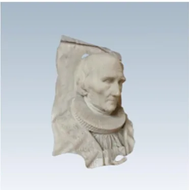
[image:4.544.172.358.263.450.2]Further to this discussion, Yastikli (4) provides a useful overview of digital photogrammetry and laser scanning, while also introducing the terminology ‘stereo photogrammetry’. This is applied in a similar manner to traditional photogrammetry, but often using hundreds of captured photographic images, perhaps offering the possibility of a route through which photogrammetry could be used to capture information about increasingly complex architectural services and features. Software available for use within mobile technology, utilizing the cloud for calculation of the point cloud and mesh (Autodesk 123D), supports digitisation of an object, automatic detection of co-ordinates in photographic images (with little expertise required) and ultimately, the rapid development a to-scale model (digital or 3D printed). Although primary geared towards the collection and establishment of models which support surface modelling, the technique has some commonality with approaches geared towards the collection of overall site or environment measurements, including those geared towards indoor or contained environments (5). Figure 3 illustrates a 3D model of a church sculpture, produced by the author, using 123D Catch. Freely available cloud-based software supports the export of such data as modifiable 3D surface models, which can in turn be incorporated in typically used architectural packages such as 3DS Max and in turn to most BIM packages.
Fig. 3. Example of a 3D surface model, produced using Autodesk 123D Catch.
Nevertheless, and despite the data rich nature of the resultant point clouds, individual points collected on-site are not intrinsically geometrically connected, and contain little data beyond their location in space (6). A significant amount of post-processing may be required on the part of the architectural model, although the widespread availability of both open source and proprietary solutions to deal with the transformation of point cloud data into surface mesh models means that the incorporation of such data with an architectural and building information models can begin to form the basis for models of new design work.
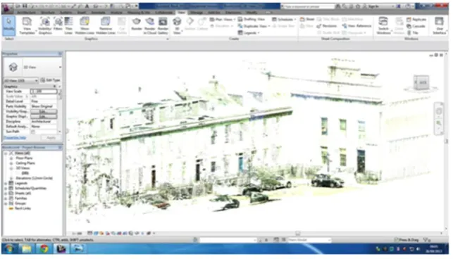
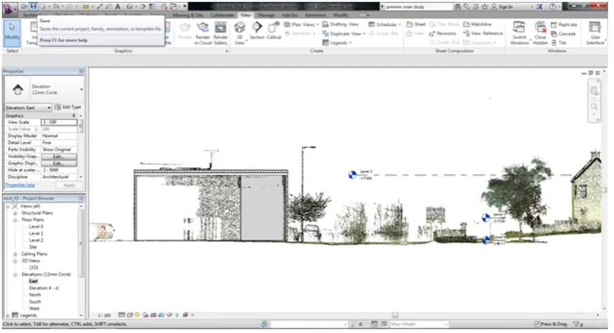
However, the environment shown in figure 2 is far more complicated, in that it shows elements of natural landscaping, housing construction from sandstone, surface paving and ironwork. The demands of an information rich architectural model are such that each element is required to be defined individually, with an indication where there may be a need to recognise physical relationships between elements. For example, and in the case of the housing illustrated in figure 2, there is a requirement for the architectural modelling team to identify various elements, including the walls, roof, openings and any design details. Figure 4, as an example, shows scan data recorded in a streetscape where the buildings were originally constructed in the early 1800s. This raw data allows the design team to view the existing site in 3 dimensions, but vital information concerning the age, materials, history, elements thicknesses and a basic differentiation between elements is missing (7). The data has been imported to Autodesk REVIT in this case as a point cloud, which then requires referencing to horizontal levels within the model, but provides an accurate (to 2mm) and to scale (1:1) template from which the remainder of the 3D model can be derived.
Fig. 4. 3D high definition scan of a streetscape imported to REVIT.
At this stage in the modeling process, it becomes necessary to consider the purposes to which the eventual BIM model will be put. In the case of the environments and features considered thus far in this paper, one could argue that the manner in which the three-dimensional information has been rapidly collected on site lends itself naturally to a visually acceptable representation of the existing environment. Where the aim of the design team was to continue towards a situation where new design work could be similarly represented in a photorealistic environment, and were this was the main or sole aim of the modelling work, then one might argue that any discussion regarding the use of information rich models might be deflecting attention away from the ultimate aims of the design process. However, this paper argues that the prevalence of information models within architectural design indicates that the incorporation of three-dimensional as-built environmental information is likely to become not only increasingly available to the design team, but that ways in which to regard that information as a template for a new design work will become increasingly valued as part of the design decision-making process.
3.Incorporation in architectural modelling environments
suchlike, scan data taken from architectural sources will include numerous elements and materials, the meaning and detail of which is vital to architectural design process.
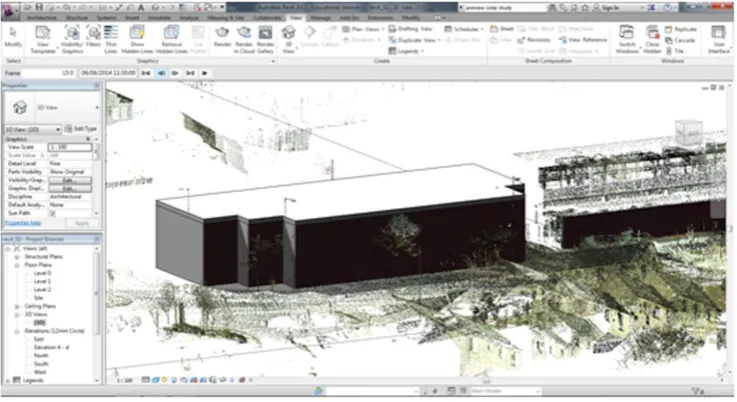
[image:6.544.50.496.179.430.2]At the design stage, then, the translation of data into a form, which can interact or inform new design work (e.g. through the compilation of a surface model, or through the production of 3D printed representations of the cloud data), becomes a key part of the design process (8). The point cloud itself (from either 3D scanning or photogrammetry) does not contain information beyond that of the geometry and potentially colour of the scene or object. Therefore, the modeler will still be required to develop an information-rich model, containing information about the materials, performance, installation and specification. The process used to incorporate the point cloud captured in figure 2 within a BIM environment is illustrated in figures is 5 and 6.
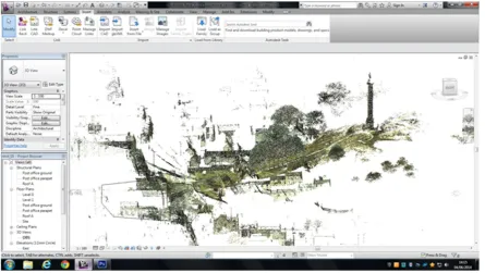
Fig. 5. Raw scan data incorporated within the REVIT BIM environment.
Figure 5 is provided here to indicate the extent to which software such as REVIT is capable of importing large scale point cloud data, albeit as a single entity to be used largely as a template for further modelling work. The data is imported at a scale of 1:1, vast maintaining the high degree of geometrical accuracy which is achieved through the use of high-definition laser scanning equipment. However, the point cloud (at least in the case of the dataset considered here) contains neither information pertaining to the geographical location of the data, or the height of the scan data relative to standard horizontal points (such as datum levels). Therefore, figure 6 has been provided to illustrate the insertion of horizontal levels within the point cloud environment, to which the BIM model itself can refer.
Fig. 6. Insertion of levels within the BIM point cloud.
For example, the model is able to provide a high degree of detail regarding the physical layout and scale of a building, but what that scan might mean in terms of construction technique, materials and structure will be missing. This is quite a different situation to that facing the modeller of a new piece of construction work, where they will need to deal with neither uncertainties regarding such elemental characteristics, or indeed aspects of the design which may be influenced by wear and tear and the history of the existing environment.
4.Application within environmental design
During the operational life cycle, a specific challenge regarding the potential benefits of using rapid data collection techniques is the integration of this data within BIM to support facilities management, including energy analysis. There are various speculations about the most suitable method for integration with BIM for analysis, especially at the early stages of the design process (10). A major benefit of using BIM to model the built environment is that all of the major software packages are built on a foundation which presumes that any objects contained within the environment exist within a larger modelspace.
Fig. 7. Building inserted within point cloud, using BIM elemental features.
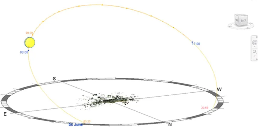
[image:8.544.69.497.379.592.2]Fig. 9. Sun path simulation, including retained point cloud environment.
The manner in which this operates is illustrated in figure 8, where the model environment (including the point client data itself) is located at the center of the Sun Path diagram. The model is able to locate buildings and objects according to environmental data specific to any given location (where possible, using actual geographical coordinates or place names). In the case of the model shown, for example, it has been located in Elgin, in the North East of Scotland, where the initial scan took place. Figure 9 then illustrates a still image taken from a daylight simulation study, within which we can observe a building whose structural form and scale has been extrapolated from the underlying point cloud. It would, of course, have been possible to derive some of this geometrical data using either propriety or open source software, thus resulting in a surface model (11). In the case of this model, the researchers chose to reconstruct the building using BIM elements, so as to preserve some degree of information richness in the underlying model. A further benefit, which derives from retaining the point cloud itself within the model environment, can also be observed in figure 9. This relates to the fact that the HD scan is able to collect detailed 3D information pertaining to environmental features, such as trees and other ornamental or natural objects within a scene. Retaining such objects within the 3-D environment arguably provides some degree of visual realism for the model, but could also be of great use should models purpose begin to extend into the realm of user perception or satisfaction studies. It should be noted, however, that the sun path analysis is unable to make direct use of the point cloud data, as BIM software is object-oriented and relies on objects which are attached to information concerning their form, scale and environmental behavior.
5.Workflow from data collection to analysis
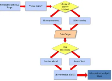
Therefore, a workflow for the capture of information, where the intention is to incorporate this within a BIM environment, must also include the recording of detailed information about material characteristics for objects and features in a scene (figure 10).
Fig. 10. Suggested workflow for incorporation of site data in BIM environment.
As recognised within the suggested workflow, consideration needs to be given to site specific concerns, including any challenges which may be presented in process of undertaking recording of site data. Therefore, undertaking a visual survey prior to the selection of survey method or methods is vital. Likewise, a consideration of post-processing should be undertaken, to decide if the model is required to provide mainly a representation of appearance (in which case surface modelling will be crucial), or whether in may be acceptable to use the point cloud as a basis for the construction of a new BIM model (as was the case in this paper). What is perhaps obvious from a consideration of BIM, and its purpose as an information-rich approach to the representation of architecture, is that the underlying data (regarding materials and material specification) will ultimately drive the design decisions which can be supported through its use.
6.Summary and conclusions
Acknowledgements
The authors wish to thank Graeme Laing of Leica Geosystems Ltd, for his assistance with the collection of scan data in Elgin. They would also like to extend their gratitude to Nancy Anderson of Robert Gordon University for her assistance with establishment of the BIM environmental model, and running of the sun path analysis.
References
1. El-Hakim SF, Beraldin J-, Picard M, Godin G. Detailed 3D reconstruction of large-scale heritage sites with integrated techniques. IEEE Comp Graph and Appl 2004; 24(3):21-9.
2. 3D Data Acquisition by Terrestrial Laser Scanning for Protection of Historic Buildings. Proceedings of the International Conference on Wireless Communications, Networking and Mobile Computing Conference, WICOM; 2007.
3. Al-Kheder S, Al-Shawabkeh Y, Haala N. Developing a Documentation System for Desert Palaces in Jordon using 3D Laser Scanning and Digital Photogammetry. J of Archaeol Sci 2009; 36:537-46.
4. Yastikli N. Documentation of cultural heritage using digital photogrammetry and laser scanning. J of Cult Heritage 2007; 8(4):423-27. 5. Ellul C, Gupta S, Haklay M, Bryson K. A Platform for Location Based App Development for Citizen Science and Community Mapping. In:
Krisp JM, editor. Progress in Location-Based Services. Lecture Notes in Geoinformation and Cartography Heidelberg. Springer Berlin; 2013. p. 71-90.
6. Anil EB, Tang P, Akinci B, Huber D. Deviation analysis method for the assessment of the quality of the as-is Building Information Models generated from point cloud data. Aut in Constr 2013; 35:507-16.
7. Bebis ea, editor. Analysing User Needs for a Unified 3D Metadata Recording and Exploitation of Cultural Heritage Monuments System. 9th International Symposium, ISVC 2013; July 29-31; 2013.
8. Laing R., Scott, J. The Devil is in the Detail. Electronic Visualisation and the Arts (EVA 2011); 6-8 July 2011; 2011. 9. Pickford L. Show and tell. RICS Constr J 2014 (June/July):24, to appear
10. Eadie R, Browne M, Odeyinka H, McKeown C, McNiff S. BIM implementation throughout the UK construction project lifecycle: An analysis. Aut in Constr 2013; 36:145-51.