© Faculty of Mechanical Engineering, Belgrade. All rights reserved FME Transactions (2018) 46, 238-244 238
Received: March 2017, Accepted: December 2017 Correspondence to: Dr Mohamad Fotouhi
Advanced Composites Centre for Innovation and Science, University of Bristol, Bristol BS8 1TR, UK
E-mail: m.fotouhi@bristol.ac.uk
doi:10.5937/fmet1802238F
Mohamad Fotouhi Research Associate University of Bristol Advanced Composites Centre for Innovation and Science UK
Putu Suwarta PhD student University of Bristol Advanced Composites Centre for Innovation and Science UK
Meisam Jalalvand Senior Research Associate University of Bristol Advanced Composites Centre for Innovation and Science UK
Gergely Czél Reseach Fellow Budapest University of Technology and Economics Hungary Senior Research Associate University of Bristol UK
Michael R. Wisnom Professor University of Bristol Advanced Composites Centre for Innovation and Science UK
Acoustic Emission Monitoring of Thin
Ply Hybrid Composites under Repeated
Quasi-Static Tensile Loading
This paper investigates the applicability of the acoustic emission (AE) technique for identification of the damage onset and accumulation in S-Glass/TR30-Carbon hybrid laminates under repeated quasi-static tensile loading. The samples were made of 2 layers of unidirectional thin carbon prepreg plies which were sandwiched between 2 standard thickness S-glass prepreg plies. Analysis of the AE results shows that there are two types of events regarding energy and amplitude ranges of the AE signals. The signals with low values are found to be related to the delamination of the carbon/glass interface whereas the signals with high values are linked with the carbon layer fragmentation. There are more friction related AE signals during the unloading stage than the loading stage due to collision and rubbing between existing crack faces. Increasing the strain level increases the number of fragmentations and the AE technique is able to quantify this. It is concluded that the AE technique can be used to evaluate the number of fragmentations and can identify the damage evolution of the hybrid laminate under repeated quasi-static tensile loading.
Keywords: Carbon/glass hybrid, Pseudo ductility, Acoustic emission, Fragmentation, Delamination.
1. INTRODUCTION
Polymer matrix composites consist of fibres in a polymer matrix, where the high modulus fibres [1] overcome the low modulus and temperature limitations of the polymer; be reinforced with synthetic or natural fibers [2-5]. These reinforced polymers are strong and stiff and they have high specific strength and specific stiffness. In addition, they have improved fatigue resis– tance and higher creep resistance than similar structures made from steel [6,7]. As a result, reinforced polymers find extensive use in many fields [8-11], such as aerospace, automobiles, sports and corrosion-resistant equipment.
However, a fundamental and yet unsolved limitation of conventional high performance polymer matrix composites is their brittle and catastrophic failure. The failure happens with no significant damage or warning. As an example, the barely visible impact damage (BVID) caused by low-velocity impacts, such as bird strikes and tool drops [12], BVID can cause internal damage [13-15] (e.g. delamination) which is not visible from the surface. Therefore, structures that satisfy a visual inspection, can fail suddenly at loads much lower than expected. To ensure safe operation, currently a
much greater safety coefficient is applied for com– posites, than for more ductile materials. These design limitations prevent the designer to regard composites as suitable for many applications in which there are unpre– dictable loading conditions and catastrophic failure is not accepted. Due to these limitations of currently avai– lable high performance composites, pseudo-ductile composites that can fail gradually are of exceptional interest and could potentially offer a notable increase in the applications of composites.
Hybridising different fibres and in many previous works, carbon and glass layers, is a successful approach to address the lack of ductility in composite laminates [16-20].
High performance carbon fibre composites offer ex– ceptional stiffness- and strength-to-weight ratios, but suffer from brittle failure. Recently, gradual failure and pseudo-ductile stress-strain response were observed in carbon/glass composite materials [21-25]. Their results showed that as the failure strain of carbon fibres is lower than that of the glass fibres, the first damage occurs in the carbon layer and the following failure mechanisms in the specimen are influenced by the interfacial toughness, material properties, and the thickness of the layers. In those studies, it was observed that in pseudo-ductile la– minates, made from hybrid of high modulus thin-ply carbon and standard thickness glass prepregs, delami– nation of the carbon/glass interface and fragmentation of the carbon layer were the main damage modes.
FME Transactions VOL. 46, No 2, 2018 ▪ 239
design of more general layups. But the characterisation of these damage modes is a complicated matter, especially in thick and non-transparent laminates.
Acoustic emission (AE) as an online monitoring technique has good potential to identify active damage mechanisms.
The AE technique is the phenomenon of radiation of transient elastic waves (acoustic events) released by a sudden redistribution of stress in a material due to crack formation, plastic deformation, etc. This technique has been used by different researchers for damage chara– cterisation of composite materials. Successful results have been reported for damage characterization of composite laminates using the AE parameters. Different frequency, energy and amplitude ranges were observed for different damage mechanisms such as fibre brea– kage, matrix cracking and delamination [26-32].
In our previous work, the AE technique was found to be an applicable method to characterise the damage mechanisms in thin-ply carbon/S-Glass laminates under tension loading [33,34]. It was found that energy and amplitude ranges of the AE signals are different for the pseudo-ductile damage mechanisms. The results were also verified by direct visual observations of the cor– responding damage mechanisms.
The aim of this study is to investigate the applicability of the AE technique for identification of the damage onset and accumulation in S-Glass/TR30-Carbon hybrid laminates under repeated quasi-static tensile loading. For this reason, pseudo-ductile hybrid laminates were subjected to a repeated quasi-static tensile loading and the generated failure mechanisms were monitored using the AE technique.
2. EXPERIMENTAL PROCEDURES
2.1 Materials
[image:2.595.312.537.213.350.2]The utilised materials are standard thickness glass/ epoxy prepreg and thin carbon/epoxy prepreg. Table 1 gives more information on the characteristics of the prepregs. UD S-glass/913 epoxy prepreg with the fibre tensile modulus of 88 GPa and the fibre failure strain of 5.5% was used as the high strain material of the hybrid laminate. The low strain material is a thin carbon prepreg from SK Chemicals (South Korea) under the trade name of SkyFlex USN020A. The fibre failure strain and modulus of the carbon fibre are 1.9% and 234 GPa, respectively. More information regarding the prepregs are given in Table 1. K50 epoxy resin which is a SK Chemical’s type resin is the corresponding matrix in the thin USN020A prepreg.
Table 1. Properties of the utilised prepregs.
Type of Prepreg TR30/epoxy S-glass/epoxy Nominal thickness of the
prepreg after curing (mm) 0.029 0.155 Volume fraction of fibre (%) 41 50
2.2 Specimen design
As illustrated in Figure 1, the lay-up was designed using the damage mode map [12] in order to have a combi–
[image:2.595.318.535.568.714.2]nation of both stable delamination and fragmentation in the carbon layer. From Figure 1, different failure modes may occur by changing the percentage of the carbon layers thickness to the thickness of the laminate (relative thickness) and absolute thicknesses of the carbon layer. From Figure 1, the laminate was designed in a way to have fragmentation and dispersed delamination damage mechanisms. Due to the translucent nature of the glass/epoxy surface ply, the failure modes were observable and it was possible to correlate the obtained AE signals to the actual damage accumulation appeared during the test i.e., ply fragmentation and carbon/glass interface delamination.
Figure 1. Pseudo-ductile strain distribution for the laminate made with 2 plies of TR30 carbon prepregs sandwiched between 2 S-glass plies.
The pseudo-ductile strain, as shown in Figure 2, is defined as the extra strain between the final failure point and the initial slope line at the failure stress level.
2.3 Specimen manufacturing
The laminate was fabricated by sandwiching 2 TR30 carbon plies between 2 S-glass plies. As the glass pre– preg was translucent it was possible to observe the damage visually. The laminate was cured for 60 minutes at 125 °C and 0.7 MPa as recommended by the supp– liers. A diamond cutting wheel was used to cut the spe– cimens. Finally, 40 mm long tabs of glass fabric/epoxy were bonded to the ends of the specimens with a two component epoxy adhesive.
Figure 2. Schematic of the typical stress–strain graph of a thin-ply hybrid with pseudo-ductility.
[image:2.595.55.285.671.719.2]240 ▪ VOL. 46, No 2, 2018 FME Transactions
[image:3.595.67.265.111.227.2]240 mm, gauge length: Lg=160 mm, width: W=20 mm, variable thickness: h for the UD sublaminates and overall length: 120 mm, gauge 12, length: Lg=64 mm, width: W=16 mm.
Figure 3. Specimen schematics.
2.4 Test procedure
Repeated quasi-static tests were carried out using a universal hydraulic computer controlled Instron 8801 with a 25 kN load cell. The test was conducted under disp– lacement control at a cross-head speed of 2 mm/min for both the loading and unloading phases, with immediate reloading. Seven cycles were chosen, each with a certain displacement limit, after which the load returns to zero. The nominal length, width and thickness of the inves– tigated specimens were 240, 160 and 20 mm, respectively. An Imetrum video gauge system was utilised to measure the strains by tracking the white points painted over a particular gauge length on the laminate face.
Figure 4. Schematic of the experimental setup, schematic and experimental picture.
A PCI-2 made by PAC Company was used to record the AE signals. The maximum sampling rate of the
device was 40 MHz. The threshold and the gain selector of the preamplifier value were set to 40 dB. The AE sensors were two PAC R15 resonant-type and single-crystal with the frequency range of 20–900 kHz. The test sampling rate was 5 MHz. The surface of the sensor was covered with silicon grease to provide good acoustic coupling between the specimen and the sensor. The test sampling rate was 5 MHz. A pencil lead break procedure was used to calibrate the data acquisition system for each of the specimens. After the calibration step, the AE signals were recorded during the tests as illustrated in Figure 4. Schematic definition of the fea– tures of an AE signal such as duration, rise time, amplitude, energy and count are presented in Figure 5.
All tests were conducted under standard and stable temperature and humidity conditions to preserve the integrity of the coupons [35].
Figure 5. The definitions for acoustic-emission parameters [36].
3. RESULTS AND DISCUSSION
[image:3.595.335.521.262.401.2]3.1 Quasi-static tensile test results:
Figure 6 shows a typical stress–strain graph and its rela– tionship with AE energy for a typical hybrid specimen, whose loading was interrupted before the final failure. The graph shows that the specimen fails in the desired pseudo-ductile manner, with carbon ply fragmentation and stable delamination.
[image:3.595.64.274.418.729.2]Figure 6. Stress–time and AE event energy distribution for a typical tested specimen. Red dots are showing the AE energies.
[image:3.595.320.536.562.694.2]FME Transactions VOL. 46, No 2, 2018 ▪ 241
specimen. At this stage, there are some weak AE events that might be related to some micro-scale damage around the edges of the sample e.g. single fibres coming off the edge and/or grip rubbing effects. These damage mechanisms do not have a considerable effect on the specimen’s integrity.
[image:4.595.97.245.255.369.2]The first significant AE energy signals were regis– tered near the plateau where the onset of macroscopic damage happened. This means that the obtained AE signals that appeared in this region were due to frag– mentation and dispersed delamination. The specimen’s appearance also changed from fully black to a tiger striped pattern, as shown in Figure 7. The well bonded areas appear black, and within the locally delaminated light areas, the cracks in the carbon layer are visible as sharp bright lines. The observed damage modes agreed with the expectations from the damage mode maps.
Figure 7. Microscopic images from the surface of a typical tested sample, interrupted before final failure, showing the fragmentation path and delaminated areas around the cracks.
[image:4.595.314.538.431.606.2]3.2 Quasi-static cyclic tensile test results:
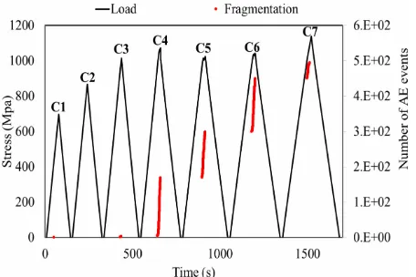
Figure 8 shows a typical load-strain curve for repeated quasi-static tensile tests of the investigated layup. The chosen strains, calculated from the video gauge were: C1: 1.33 %, C2: 1.63 %, C3: 1.89 %, C4: 2.07%, C5: 2.32%, C6: 2.71 %, and C7: 3.12 %, where C stands for “Cycle”. Until the third cycle, the applied strain is lower than the failure strain of the carbon layer (i.e. 1.9 %) and there is an appearance of a plateau in the fourth cycle, which then evolved in the other cycles. After the third cycle, there is a residual strain or permanent deformation at zero load and by increasing the strain level the initial tensile modulus decreases. The important factor responsible for the changes in the stress-strain diagram is the occurrence of delamination of the carbon/glass interface and the carbon ply fragmentation.
Figure 8. Stress-strain curve for a typical specimen subjec– ted to cyclic loading. The dashed line corresponds to the damage initiation.
In order to extract more useful information about the damage mechanisms of the tested specimens, the AE technique was used. A previous study reported that it is possible to characterise certain mechanisms by studying the energy and the amplitude of the AE events during the damage accumulation [33,34]. It is concluded that higher amplitudes and energies represent fibre fragmentations, medium values are mostly in connection with delamination, while the lower ones are noise. It was found that delamination between the carbon/glass interface occurred between 60-85 dB amplitude and 30-800 aJ energy, while these values were 75-100 dB and 800-65000 aJ in the case of carbon fibre fragmentation.
Using this classification technique, the AE signals were separated into three clusters. The results are illustrated in Figures 9 and 10. As illustrated, the damage mechanisms are identified by the AE events with different energy and amplitude levels. The clear and significant AE events start when the plateau on the stress-strain curve begins. There are also some fragmentation and delamination related events before cycle 4, due to the relaxation of the internal stresses developed due to issues such as free fibres at the edges of the specimens.
[image:4.595.76.257.617.749.2]Around the peak loads there are higher intensity AE signals, whereas the lower amplitude and energy signals appear between the load peaks as well as when unloading the sample. The lower intensity signals, i.e. the noise, could be friction due to existing damage mechanisms. There are more noise related AE signals during the unloading stage than the loading stage.
Figure 9. Stress-time and distribution of AE event energy for the hybrid laminate.
242 ▪ VOL. 46, No 2, 2018 FME Transactions Figure 10. Stress-time and AE event amplitude distribution
[image:5.595.58.283.265.433.2]for the hybrid laminate.
Figure 11. Cumulative AE event energy for each class of AE signal for a typical hybrid laminate.
Each AE event is regarded as one damage event. The number of damage events is illustrated in Figure 12. This number of fragmentation events prior to the final peak point and the average energy content for each of them are 495 and 2445 aJ, respectively.
Figure 12. Number of fragmentation type AE events for the hybrid laminate.
4. CONCLUSION
In this paper, the AE technique is utilised to identify the damage modes in thin-ply UD carbon/glass hybrid laminates under repeated quasi-static tensile loading.
Fragmentation of the carbon plies and delamination of the carbon/glass interfaces are found to be the main damage sources for the AE signals. It is concluded that the AE technique can be used to evaluate the number of fragmentations and can identify the damage evolution of the hybrid laminate under repeated quasi-static tensile loading.
The proposed method is very useful as an effective way to accurately detect fibre fragmentation and to track the damage progression and accumulation in more complex loading conditions such as cyclic loading.
ACKNOWLEDGMENT
This work was funded under the UK Engineering and Physical Sciences Research Council Programme Grant EP/I02946X/1 on High Performance Ductile Composite Technology in collaboration with Imperial College, London. Gergely Czél acknowledges the Hungarian Academy of Sciences for funding through the Post-Doctoral Researcher Programme fellowship scheme, the János Bolyai scholarship and the Hungarian National Research, Development and Innovation Office - NKFIH, for funding through grant OTKA K 116070. The authors acknowledge Hexcel Corporation for supplying materials for this research. All underlying data are included in full within this paper.
REFERENCES
[1] de Camargo F.V., Guilherme, C.E.M., Fragassa, C. and Pavlovic, A.: Cyclic stress analysis of polyester, aramid, polyethylene and liquid crystal polymer yarns, Acta Polytechnica, Vol. 56, No. 5, pp. 402–408, 2016.
[2] De Paola, S. et al.: Green Composites: A Review of State of Art, in: Proc. 30th Danubia Adria Symposium on Advanced Mechanics, 25-28.09.2013, Primosten, pp. 77-78.
[3] Fragassa, C.: Effect of Natural Fibers and Bio-Resins on Mechanical Properties in Hybrid and Non-Hybrid Composites, in: Proceedings of the 8th Conference on Times of Polymers & Composites: From Aerospace to Nanotechnology, 19-23.06. 2016, Ischia.
[4] Fragassa, C., Pavlovic, A. and Santulli, C.: Mec– hanical and impact characterisation of flax and basalt fibre bio-vinylester composites and their hybrids.
Composites - Part B., Vol 137, pp. 247-259, 2018 [5] Hyseni, A., De Paola, S., Minak, G. and Fragassa,
C.: Mechanical Characterization of EcoComposites, in: Proc. 30th Danubia Adria Symposium on Advanced Mechanics, 25-28.09.2013, Primosten, pp. 175-176.
[6] Beaumont P.W.R., Soutis C., Hodzic A. (Editors): Structural integrity and durability of advanced composites: Innovative modelling methods and intelligent design, Woodhead Publishing - Elsevier, Cambridge, UK, 2015.
[image:5.595.58.286.529.681.2]FME Transactions VOL. 46, No 2, 2018 ▪ 243
Helicopter Rotor Blades, Journal of Testing and Evaluation (JTE), Volume 39, Issue 2 (March 2011), ASTM International, USA, pp. 237-242.
[8] Maglio, S., de Camargo F.V., Rodrigues M.R.: Benefits and Risks in the Use of Composite Mate– rials in Solar Vehicles, Key Engineering Materials, Vol. 754, pp. 51-54, 2017.
[9] Rašuo, B.: Experimental Study of the Structural Damping of Composite Helicopter Blades with Different Cores, Plastics Rubber & Composites, Vol. 39, No. 1, pp. 1-5, 2010.
[10]de Camargo, F.V. F.V., Fragassa, C., Pavlovic, A. and Martignani, M.: Analysis of the Suspension Design Evolution in Solar Cars, FME Transactions, Vol. 45, No. 3, pp. 394-404, 2017.
[11] Minak. G., Fragassa, C., de Carmago F.V.: A Brief Review on Determinant Aspects in Energy Efficient Solar Car Design and Manufacturing, in: Campana G. et al. (Eds.): Sustainable Design and Manufacturing 2017 - Smart Innovation, Systems and Technologies, Vol.68 Springer International Publishing, Cham Switzerland, pp. 847-856, 2017. [12] Kreculj, D., Rašuo, B., Review of impact damages
modelling in laminated composite aircraft structures, Technical Gazette, Vol.20 No.3, pp. 485-495, 2013. [13] Boria, S., Pavlovic, A., Fragassa, C. and Santulli,
C.: Modeling of Falling Weight Impact Behavior of Hybrid Basalt/Flax Vinylester Composites, Proce– dia Engineering, Vol. 167, pp. 223–230, 2016. [14] Saghafi, H., Brugo, T., Zucchelli, A., Fragassa, C.
and Minak, G.: Comparison the effect of pre-stress and curvature of composite laminate under impact loading, FME Transactions, Vol. 44, No. 4, pp. 353-357, 2016.
[15] de Camargo, F.V., Pavlovic, A.: Fracture Evalu– ation of the Falling Weight Impact Behaviour of a Basalt/Vinylester Composite Plate through a Multi– phase Finite Element Model, Key Engineering Materials, Vol. 754, pp. 59-62, 2017.
[16] Garinis D., Dinulovic M, Rašuo B.: Dynamic Analysis of Modified Composite Helicopter Blade, FME Transactions, Vol. 40 No 2, pp 63-68, 2012. [17] Summerscales, J., Short, D.: Carbon fibre and glass
fibre hybrid reinforced plastics, Composites, Vol. 9, pp. 157–66, 1978.
[18] Manders, P.W. and Bader, M.G.: The strength of hybrid glass/carbon fibre composites, J Mater Sci, Vol. 16, No. 8, pp 2233–2245, 1981.
[19] Swolfs, Y., Gorbatikh, L., Verpoest, I.: Stress concentrations in hybrid unidirectional fibre-reinforced composites with random fibre packings, Compos Sci Technol, Vol. 85, pp. 10–16, 2013. [20] Swolfs, Y. et al.: Fibre hybridisation in polymer
composites: a review, Compos Part A Appl Sci Manuf, Vol. 67, pp. 181–200, 2014.
[21] Czél, G., etal.: Demonstration of pseudo-ductility in high performance glass-epoxy composites by hybridisation with thin-ply carbon prepreg, Compos Part A Appl Sci Manuf, Vol. 52, pp. 23–30, 2013. [22] Jalalvand, M., Czél, G. and Wisnom, M.R.: Para–
metric study of failure mechanisms and optimal
configurations of pseudoductile thin-ply UD hybrid composites, Composites Part A: Applied Science and Manufacturing, Vol. 74, pp. 123–131, 2015. [23] Jalalvand, M., Czél, G. and Wisnom, M.R.:
Damage analysis of pseudo-ductile thin-ply UD hybrid composites – A new analytical method, Composites Part A: Applied Science and Manufac– turing, Vol. 69, pp. 83–93, 2015.
[24] Jalalvand, M., Fotouhi, M., Czél, G., Wisnom M.R.: Avoiding free edge delamination in quasi-isotropic pseudo-ductile hybrid laminates-by mate– rial dispersion or layer angle dispersion?, in:
ECCM17 17th European Conference on Composite Materials, 26-30.06.2016, Munich.
[25] Czél, G., Rév, T., Jalalvand, M., Fotouhi, M., and Wisnom, M.R.: Demonstration of pseudoductility in quasi-isotropic laminates comprising thin-ply UD carbon/epoxy hybrid sublaminates, in:
ECCM17 17th European Conference on Composite Materials, 26-30.06.2016, Munich.
[26] Dinulović, M., Rašuo, B., Krstić, B., Bojanić, A.: 3D random fiber composites as a repair material for damaged honeycomb cores, FME Transactions, Vol. 41 No 4, pp 325-332, 2013.
[27] Fotouhi, M. and M. Ahmadi.: Acoustic Emission based study to characterize the initiation of mode I delamination in composite materials, Journal of Thermoplast Composite Materials, Vol. 29, No. 4, pp. 519–537, 2016.
[28] Fotouhi, M., Saeedifar, M., Sadeghi, S., Ahmadi, M. and Minak G.: Investigation of the damage mechanisms for mode I delamination growth in foam core sandwich composites using Acoustic Emission, Struct Health Monit, Vol. 14, No. 3, pp. 265–280, 2015.
[29] Fotouhi, M. and Ahmadi, M.: Investigation of the mixed-mode delamination in polymer-matrix composites using acoustic emission technique, Journal of Reinforced Plastics and Composites, Vol. 33, No. 19, pp. 1767-1782, 2014.
[30] Heidary, H., Zarif Karimi, N., Ahmadi, M., Rahimi, A. and Zucchelli, A.: Clustering of acoustic emission signals collected during drilling process of composite materials using unsupervised classifiers. Journal of Composite Materials, Vol. 49, No. 5, pp. 559–571, 2015.
[31] Fotouhi, M., Pashmforoush, F., Ahmadi, M. and Refahi, A.: Monitoring the initiation and growth of delamination in composite materials using acoustic emission under quasi-static three-point bending test, J Reinf Plast Compos, Vol. 30, pp.1481-1493, 2011.
[32] Zarif Karimi, N., Minak, G. and Kianfar, P.: Analysis of damage mechanisms in drilling of composite materials by acoustic emission, Composite Structures, Vol. 131, pp.107–114, 2015. [33] Fotouhi, M., Suwarta, P., Jalalvand, M., Czel, G.
244 ▪ VOL. 46, No 2, 2018 FME Transactions 17th European Conference on Composite
Materials, 26-30.06.2016, Munich.
[34] Fotouhi, M., Suwarta, P., Jalalvand, M., Czel, G. and Wisnom, M.R.: Detection of fibre fracture and ply fragmentation in thin-ply UD carbon/glass hybrid laminates using acoustic emission, Compo– sites Part A: Applied Science and Manufacturing, Vol. 86, pp. 66–76, 2016.
[35] Zivkovic, I., Pavlovic, A., Fragassa, C. and Brugo, T.: Influence of moisture absorption on the impact properties of flax, basalt and hybrid flax/ basalt fiber reinforced green composites. Composites Part B, Vol. 111, pp 148-164, 2017.
[36]Huang, M., Jiang, L., Liaw, P.K., Brooks, C.R., Seeley, R. and Klarstrom, D.L.: Using Acoustic Emission in Fatigue and Fracture Materials Research. Nondestructive Evaluation: Overview.
November; 50:11, 1998.
ПРАЋЕЊЕАКУСТИЧНЕЕМИСИЈЕТАНКИХ
СЛОЈЕВАХИБРИДНИХКОМПОЗИТАПОД
ПОНОВЉЕНИМКВАЗИ-СТАТИЧКИМ
ЗАТЕЗАЊЕМ
М. Фотоухи, П. Суварта, М. Јалалванд, Г. Цзeл,
М.Р. Висном
Овајрадистражујеприменљивосттехникеакус–тичке
емисије (АЕ) за идентификацију оштећења и
акумулације у S-Staklu/TR30-Grafitnim хибридним
ламинатима под поновљеним квази-статичним опте–
рећењем. Узорци су направљени од 2 једносмерна
танкаслојаугљеничногпрепрегакојасубилапостав–
љена између 2 стандардне препрег плоче С-стакла.
Анализа резултата АЕ показује да постоје две врсте
догађајакоји се односе на опсеге енергијеи ампли–
тудесигналаАЕ. Утврђеноједасусигналисанис–ким
вредностима повезани са деламинацијом повр–шине
угљеника/стакла, док су сигнали са високим вред–
ностимаповезанисафрагментацијомслојауг–љеника.
ПостојивишесигналаАЕвезанихзатрењетокомфазе
растерећењаодфазеучитавањазбогсу–дараитрљања
између постојећих површина пуко–тина. Повећавање
нивоа напрезања повећава број фрагментација и АЕ
техникајеустањудагаква–нтификује. Закљученоје
да се техника АЕ може користити за процену броја
фрагментација и може идентификовати еволуцију
хибридногламинатаподпоновљенимквази-статичним