Abstract—In the fourth Generation (4G), Location Based Service (LBS) is an important feature of radio networks and plays a significant role in mobile communication. In this paper, detailed analysis is focused on the Location Determination Technology (LDT) based on Observed Time Difference of Arrival (OTDOA) downlink positioning technique in 4G system. OTDOA is a multilateration method in which the User Equipment (UE) measures the time of arrival (TOA) of signals received from multiple base stations (eNodeB’s). The TOAs from several neighbor eNodeB’s are subtracted from a TOA of a reference eNodeB to form Observed Time Difference Of Arrival’s.Geometrically, each time (or range) difference determines a hyperbola, and the point at which these hyperbolas intersect is the desired UE location. At least three timing measurements from geographically dispersed eNodeB’s with good geometry are needed to solve for two coordinates (x,y or latitude/longitude) of the UE.
Index Terms—3rd Generation Partnership Project, Gateway Mobile Location Center, Evolved Serving Mobile Location Center, Mobility Management Entity, Secure User Plane Location, User Equipment, Packet Data Network, SUPL Location Platform
1) INTRODUCTION
Location Based Service is a standout amongst the most imperative facility that has been offered to the clients of the 3G versatile correspondence. This facility is extremely significant to a portable client particularly in a crisis circumstance and the location estimation with high precision is required.
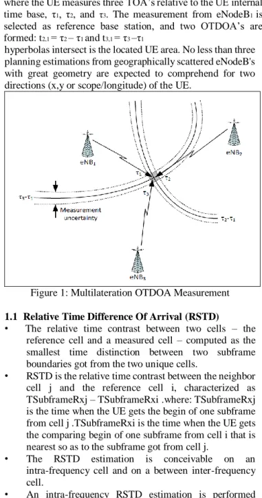
OTDOA is a multilateration technique in which the User Equipment (UE) measures the time of arrival(TOA) of signals got from multiple base stations (eNodeB's). The TOAs from a few neighbor eNodeB's are subtracted from a TOA of a reference eNodeB to shape Observed Time Difference Of Arrival's.Geometrically, each time (or range) difference decides a hyperbola, and the time when these
hyperbolas intersect is the located UE area. No less than three planning estimations from geographically scattered eNodeB's with great geometry are expected to comprehend for two directions (x,y or scope/longitude) of the UE.
Figure 1: Multilateration OTDOA Measurement 1.1 Relative Time Difference Of Arrival (RSTD)
• The relative time contrast between two cells – the reference cell and a measured cell – computed as the smallest time distinction between two subframe boundaries got from the two unique cells.
• RSTD is the relative time contrast between the neighbor cell j and the reference cell i, characterized as TSubframeRxj – TSubframeRxi .where: TSubframeRxj is the time when the UE gets the begin of one subframe from cell j .TSubframeRxi is the time when the UE gets the comparing begin of one subframe from cell i that is nearest so as to the subframe got from cell j.
• The RSTD estimation is conceivable on an intra-frequency cell and on a between inter-frequency cell.
• An intra-frequency RSTD estimation is performed when both, the reference cell i and the neighbor cell j are
Location Based Service for Observed Time Difference Of Arrival (OTDOA) Positioning
Technique in 3GPP LTE
Sowmya GM1, Nagaraj K2, Sampath Kini3
1PG Student, Dept Of CSE,NMAM Institute Of Technology, Nitte,India
2Manager-Embedded Product Design, Communications BU,TATA ELXSI,Bangalore, India
3Assistant Professor, Dept Of CSE,NMAM Institute Of Technology,Nitte,India
The OTDOA positioning method is illustrated in Figure1, where the UE measures threeTOA’s relative to the UE internal time base, τ1, τ2, and τ3. The measurement from eNodeB1 is selected as reference base station, and two OTDOA’s are formed: t2,1 = τ2 – τ1 and t3,1 = τ3 –τ1
on an same carrier bearer frequency from the UE serving cell.
•
An inter-frequency RSTD estimation is performed when both, the reference cell i and the neighbour cell j is on a distingushable carrier frequency as the UE serving cell.1.2 Basic OTDOA Navigation Equations
The TOA estimations performed by the UE are identified with the geometric separation between the UE and the eNodeB. In a 2-D Cartesian organize framework, we mean the (referred to) directions of an eNodeB as x𝑖 = [ xi, 𝑦𝑖 ]𝑇 and the (unknown) directions of the UE as x𝑡 = [𝑥𝑡 , 𝑦𝑡 ]𝑇 . The RSTD estimations are characterized as the time distinction between two eNodeB's (modulo 1-subframe (1-ms)), and hence, relate the accompanying extent differences between a neighbor eNodeB i and the reference eNodeB1.
RSTDi,1 is the time difference between an eNodeB i and the reference cell 1 measured at the UE.[5]
transmission components by permitting the handset to make a TCP/IP association straightforwardly [5].
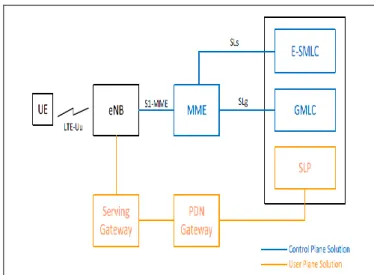
2.1 Location Services Architecture Overview
As specified in the figure 2,the location server (E-SMLC or SUPL SLP) oversees OTDOA situating for an objective deviceby acquiring RSTD estimations from the UE and giving help information to the UE to help decide this. The Location Server may likewise process (UE-helped) or confirm (UE-based) the last location estimate
In control plane arrangement, the MME gets a demand for some area benefit related with a specific target UE from another substance (e.g., GMLC or UE) or the MME itself chooses to start some area benefit in the interest of a specific target UE [8].
Figure 2: LTE LCS Architecture Overview.
2.2 LPP Procedures
The LPP procedures between location server (E-SMLC or SUPL SLP) usually consist of
(a) Capability Transfer (b) Assistance Data Transfer (c) Location Information Transfer
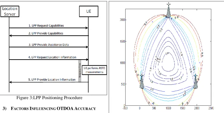
1.The location server sends a Request Capabilities message to the UE, which demonstrates the kind of abilities required.
For OTDOA, this incorporates the OTDOA-Request Capabilities UE, showing that the UE's OTDOA capacities are asked. Figure 3 depicts the sequence LPP Procedures between the location server and the UE.
2.The location server sends a Provide Assistance Data message to the UE containing OTDOA help information.[6]
The MME then sends an location services demand to an E-SMLC. The E-SMLC forms the location services ask for which incorporate exchanging OTDOA help information to the objective UE. The E-SMLC then returns the results of the area benefit back to the MME. On account of an location service asked for by an element other than the MME (e.g., UE or GMLC), the MME gives back the area benefit result to this substance. No less than two neighbor cell estimations i are required, which gives two conditions with two questions (xt, yt) if the directions of the eNodeB reception apparatuses (xi,yi) and additionally the transmit time offsets (RTDs) (Tj − Ti) are known.
Typically, more than two neighbor cell estimations are craved, and the arrangement of conditions is tackled at all least-squares, or weighted-minimum squares.
The transmit time balances (Ti−T1) ought to (ideally) be zero in a synchronized system, and the condition above characterizes the time-difference of arrival (TDOA).Geometrically, each TDOA characterizes a hyperbola, where the width of the hyperbola is dictated by the TDOA errors (ni − n1) as appeared in Figure 1
Figure 3:LPP Positioning Procedure 3) FACTORS INFLUENCING OTDOAACCURACY
3.1 Measurement Geometry: The estimation geometry affects accuracy. The most broad parameter used to evaluate the effect of the geometry on the last accuracy is the Geometrical Dilution of Precision (GDOP). The GDOP is a measure of how much the position mistake that outcomes from RSTD estimation errors relies on upon the mobile/eNodeB relative geometry. On the off chance that all the TOA estimations made by the MS to compute the RSTD's have a similar error change σ2, the situating mistake can be approximated as
𝜎𝑝𝑜𝑠 ≈ 𝐺𝐷𝑂𝑃 × 𝜎
Figure 4 indicates GDOP of three base stations as a component of the UE location.The GDOP is smallest,when the UE is situated amidst the triangle framed by three eNb's and increments rapidly as UE moves out of the focal point of triangle.
3.2 eNodeB Synchronization
The eNodeB's participating in OTDOA situating must be time-synchronized precisely and dependably for OTDOA to work. At the speed of light, each nsec of mistake in timing converts into about a foot (~0.3 m) of error in position.
Figure 4:GDOP with three eNodeB’s
As inter-eNodeB synchronization degrades, the OTDOA measurements become less accurate, the hyperbolas become
―fuzzy‖, and the position error increases proportionally. The synchronization requirements for OTDOA are much more stringent compared to the synchronization requirements for communication purposes. Table 1 summarizes some requirements for LTE eNodeB’s.
Table 1:Requirements for clock synchronization As between eNodeB synchronization corrupts, the OTDOA estimations turn out to be less exact, the hyperbolas progress toward becoming "fuzzy", and the position error increments relatively. The synchronization prerequisites for OTDOA are substantially more stringent contrasted with the synchronization necessities for correspondence purposes.
Table 1 outlines a few necessities for LTE eNodeB's.
Figure 5:Illustration of GDOP Phenomenon: Low GDOP.
To illustrate the effect of base station synchronization in light of location precision, the setup appeared in Figure 5 is viewed as: The UE is situated amidst the triangle framed by the three encompassing eNodeBs, and the UE area is ascertained expecting a specific base station clock stage exactness ϕ.
Since just the effect of base station synchronization exactness is of interest, the RSTD estimation error is thought to be zero(i.e., ni = 0 and n1 = 0) and the base station directions are known precisely. The subsequent location error as capacity of base station synchronization blunder is appeared in Figure -6.The x-pivot demonstrates the greatest check stage precision ϕ in smaller scale seconds. For instance, if the base station synchronization exactness is ±0.1 µs, the most extreme area mistake because of base station synchronization blunder alone could be up to 40 meters. Practically speaking, the real base station synchronization error might be haphazardly dispersed amongst ±ϕ and some portion of the synchronization blunder may wipe out while figuring the RSTD contrast. The figure demonstrates the most pessimistic scenario (greatest) area mistake in this three eNodeB case.
3.3 Exemplary Error Budget
1. The UE can hear no less than 3 eNodeB's with PRS SINR > - 13 dB. With 10 MHz PRS data transmission, the base precision of the RSTD estimations is superior to 5 Ts (~50 m) (segment 5.5.1). By and by, the execution (in AWGN) is normally superior to that. Accept: σUE = 40 m
2. The RSTD estimations are produced using eNodeB's with great estimation geometry, so that the GDOP is < 1 (Figure 5.5): GDOP = 0.9
3.All eNodeB's are synchronized reporting in real time interface with a precision of superior to 50 ns: σBS = 15 m
4. The eNodeB antenna coordinates are known to be
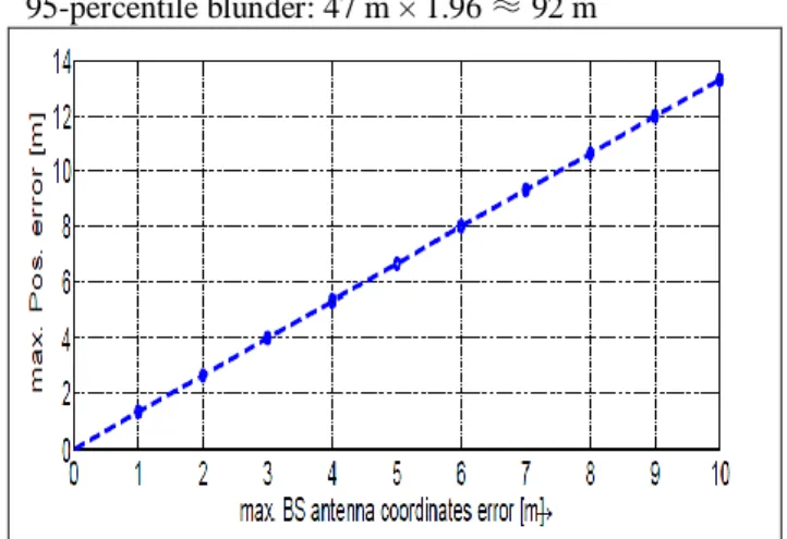
95-percentile blunder: 47 m × 1.96 ≈ 92 m
Figure 6: Impact of base station synchronization error on location accuracy.
To outline the effect of base station synchronization in light of area exactness, the arrangement appeared in Figure 5 is viewed as: The UE is situated amidst the triangle framed by the three encompassing eNodeBs, and the UE area is ascertained accepting a specific base station clock phase accuracy ϕ. Since just the effect of base station synchronization precision is of interest, the RSTD estimation error is thought to be zero(i.e., ni = 0 and n1 = 0) and the base station directions are known precisely. The subsequent location error as capacity of base station synchronization mistake is appeared in Figure 6. The x-axis demonstrates the most extreme clock phase accuracy ϕ in smaller scale seconds. For instance, if the base station synchronization exactness is ±0.1 µs, the greatest area error because of base station synchronization mistake alone could be up to 40 meters. By and by, the genuine base station synchronization error might be arbitrarily dispersed amongst ±ϕ and some portion of the synchronization mistake may scratch off while computing the RSTD distinction. The figure demonstrates the most pessimistic scenario (greatest) area mistake in this three eNodeB illustration
4) CONCLUSION
This paper discusses the functionalities for the support of Location Based Services for Observed Time Difference of Arrival (OTDOA),downlink positioning technique in 3GPP LTE system. This document describes the OTDOA location in LTE accurrently defined in 3GPP. It is intended as a one stop guide to provide an overview of the OTDOA feature for operators and manufacturers interested in the deployment of OTDOA location capabilities including references to where the standard details on each subject can be found.
Mobile Positioning: Algorithms and Optimality.
EURASIP Journal on Applied Signal Processing, Volume 2006, Article ill20858, page 1- 23
[4] J.H. Yap, S. Ghaheri-Niri and R. Tafazolli. 2002.
Accuracy and hearability of mobile positioning in GSM and COMA networks. IEEE: 350 - 354.
[5] 3GPP TS 36.331: "Evolved Universal Terrestrial Radio Access (E-UTRA); "Radio Resource Control (RRC); Protocol specification".
[6] 3GPP TS 36.355: "Evolved Universal Terrestrial Radio Access (E-UTRA); LTE Positioning Protocol (LPP)".
[7] Carrier Aggregation Mode With Multiple Uplinks and Multiple Downlinks Hamed Gheidi 1 , CA 92093, USA 2015
.
[8] 3GPP TS 29.171: "Location Services (LCS);
LCSApplication Protocol (LCS-AP)between the Mobile Management Entity (MME) and Evolved Serving Mobile Location Centre (E-SMLC); SLs interface".
[9] ―Location Based Services Positioning Techniques and applications― Mrs.Ashwini B M and Dr.Usha, IJAIEM, Volume 3 Issue 1,January 2014,India