Rotor Position Control of a Brushless DC (BLDC)
Motor using Space Vector PWM Method
G Sethulekshmy1, Sreedevi G2
1, 2
Electrical and Electronics Engineering Department, College of Engineering Trivandrum, Thiruvananthapuram, India
Abstract: Brushless DC (BLDC) motor has many applications in industries, actuators, servomotors, as assembling robots etc. The position control of this motor is needed with accuracy for such applications. In this paper, position control of BLDC motor is proposed using Space Vector Pulse Width Modulation technique with field oriented control for the accurate control of rotor position. The motor is modelled using the basic equations and field oriented control is applied. The gate pulses needed for the inverter are generated using the SVPWM method and the results are observed using MATLAB/SIMULINK.
Keywords: BLDC, brushless DC motor, SVPWM, Position, FOC, VSI, hall effect sensors
I. INTRODUCTION
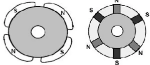
[image:1.612.83.539.383.482.2]Brushless DC (BLDC) motor consists of a permanent magnet rotor and a wire wound stator. These motors are commutated electronically and thus eliminating the need of commutator brushes [4]. An electronic sensor such as a hall effect sensor or an optical encoder detects the rotor position and the inverter control is provided using this information. Sensorless control have also been developed by various methods [11-12], in order to reduce the cost and avoid heating problems of the sensor. Fig. 2. shows the working of a BLDC motor with star connected stator winding. The three phase two level inverter shown consists of six switches that are mostly IGBTs or MOSFETs which are controlled by adjusting their gate signals [1-2].
Fig 1. BLDC motor construction. Fig 2. BLDC motor driver circuit
There are mainly two types of BLDC motors: one with inner rotor and other with outer rotor. The inner rotor type is again divided into two types: surface mounted permanent magnet type and interior permanent magnet type as shown in Fig.3. Advantages of BLDC motors over conventional DC motors are long life, high efficiency, better speed Vs. torque characteristics, and high torque-weight ratio [4]
[image:1.612.185.433.557.665.2]II. BLDC MOTOR MODELLING
For simplifying the equations governing the motor and overall model, the following assumptions are made:
A. Mutual inductance and saturation of the magnetic circuit are ignored.
B. Stator resistance, self-inductance and mutual inductance of all phases are equal and constant.
C. Hysteresis losses and eddy current losses are ignored.
D. All semiconductor switches of the inverter are ideal. [4]
[image:2.612.137.403.178.259.2]
Fig.4. BLDC motor electrical equivalent circuit
The motor is modelled using the following equations.
= + + (1)
= + + (2)
= + + (3)
Here, ‘V’denotes voltage, ‘I’ denotes current, ‘e’ denotes back emf generated in the motor, ‘R’ is the resistance and ‘L’ is the self-inductance of each phase.
The torque generated in the motor is given by : = + + (4)
The electromagnetic torque can also be represented as: = ( + + ) (5)
Where J is the rotor inertia, B is the damping constant, TLis the load torque, ωmis the mechanical speed of the rotor, ωe is the
electrical equivalent of speed of rotor.
The relation between rotor angle and speed is : = , = where P is the number of poles [4]. (6)
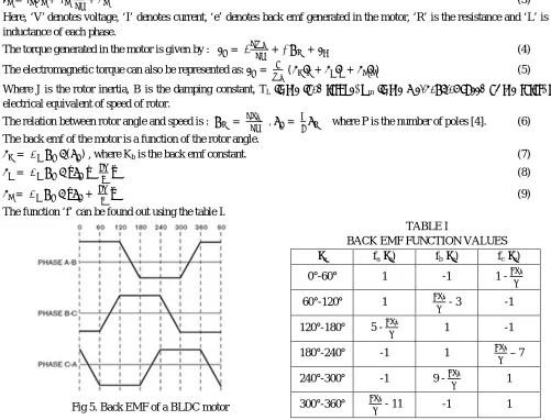
The back emf of the motor is a function of the rotor angle.
= ( ) , where Kb is the back emf constant. (7)
= − (8)
= + (9)
The function ‘f’ can be found out using the table I.
TABLE I
BACK EMF FUNCTION VALUES
θe fa(θe) fb(θe) fc(θe)
0°-60° 1 -1 1 -
60°-120° 1 - 3 -1
120°-180° 5 - 1 -1
180°-240° -1 1 – 7
[image:2.612.38.539.356.738.2]For the proper rotation of BLDC motor, the windings in the stator should be excited in a sequence. It is therefore important to determine the rotor position to obtain the correct energizing sequence which is accomplished through Hall sensor signals. There are three hall sensors which are kept at an interval of 120 electrical degrees and are embedded into the stator of the BLDC motor. The position of the motor is controlled using the information obtained from these hall sensors.
III. FIELDOREINTEDCONTROLANDSPACEVECTORMODULATION
Field Oriented Control(FOC) is also called vector control. At higher speeds, better efficiency can be achieved compared to sinusoidal PWM method.
Also better performance is obtained on dynamically changing load compared to other methods. Using FOC flux and torque can be controlled separately with less torque ripples. In this method, stator currents of the motor are measured and then adjusted to obtain 90° between stator flux and rotor flux so as to achieve maximum torque. Following are the steps implemented in FOC of a BLDC motor [7].
A. Measure the three stator currents or measure two of them and evaluate the third one using the equation + + = 0
B. Convert them using Clarke/Park Transformations to convert from stationary reference frame to rotating reference frame.
C. Compare the calculated values with reference values and input the error signals to PI/PID controllers.
D. Using Inverse Park/Clarke Transformations corresponding voltage vectors are converted to abc-waveform.
E. The voltage signals are fed to SVPWM block to generate the gate pulses needed for the inverter.
For position control applications, the rotor position obtained from the hall sensors are compared with the reference position and then converted to speed reference.
SVPWM method is an advanced pulse width modulation method which gives better DC bus voltage utilization compared to sine PWM method. Space vector Modulation method has many advantages like high output quality due to less harmonic distortion and low filter component ratings [6].
As per the block diagram shown in fig 6., FOC with SVPWM is implemented using the following equations [7]:
1) Clarke Transformation
= (10)
=
√ + √ (11)
2) Park Transformation
= cos + sin (12)
= − sin + cos (13)
3) Inverse Park Transformation
= cos − sin (14)
= sin + cos (15)
4) Inverse Clarke Transformation
= (16)
= + √ (17)
= − √ (18)
5) Magnitude and angle for SVPWM
= + (19)
Fig.6. Block diagram representing implementation of FOC
Fig.7. The sectors in space vector PWM Fig.8. a-b-c and d-q axes representation
The implementation of SVPWM is explained in detail in [6], [7], [13]. The switching time of each switch is decided according to the angle of the rotating reference vector as in [6].
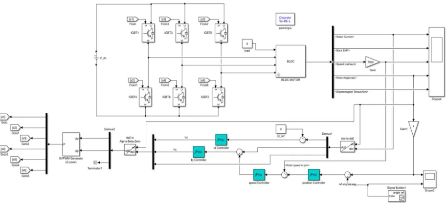
IV.MATLAB/SIMULINKIMPLEMENTATIONOFTHEPROPOSEDSYSTEM
Fig.10. SIMULINK model for position control of the motor
TABLE III
SPECIFICATIONS OF THE MOTOR USED FOR SIMULATION
No:of phases 3
No:of poles 4
Power 103 W
Voltage 24 V
Resistance per phase, Rs 0.7 Ω
Inductance per phase , Ls 0.0272 H
Back EMF constant, Kb 0.513 V/rpm
[image:5.612.57.545.339.721.2]Inertia, J 0.002
Fig 11. Reference rotor angle and developed rotor angle of the motor
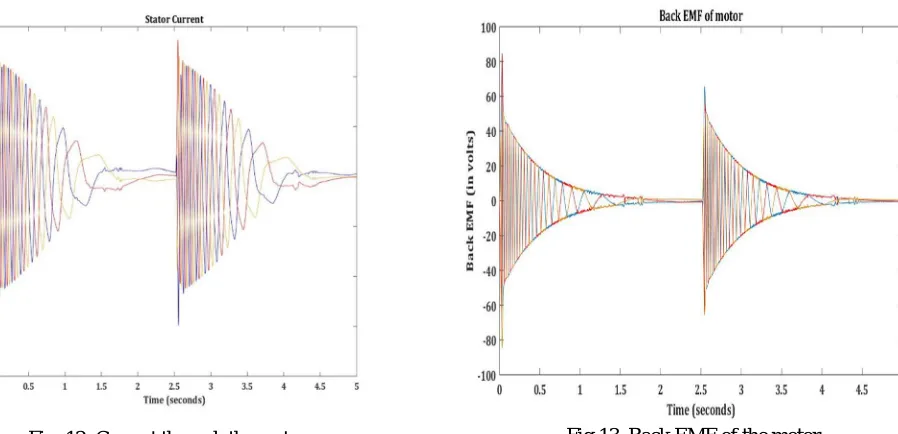
Fig. 12. Current through the motor Fig.13. Back EMF of the motor
V. CONCLUSION
Position control of BLDC motor is achieved using Field oriented control based Space Vector PWM method in the proposed system. Precision of 0.1 radians is obtained. Here the BLDC motor is operating in 180° conduction mode on no load.Performance of the proposed system can be improved much better than sine PWM method by proper tuning of PI controllers. SVPWM can be implemented using DSP according to the application and power rating of the motor.
REFERENCES
[1] B. K. Bose, “Power Electronics and Variable Frequency Drives: 39 Technology and Applications”, IEEE Press, 1997
[2] Rashid, M. H., “Power Electronics Handbook,” Academic Press, 2001
[3] R. Krishnan, “Electric Motor Drives Modelling, Analysis and Control”, Prentice Hall, 2001
[4] Vikramarajan Jambulingam, “Mathematical Modelling and Simulation of Brushless DC Motor Using MATLAB”, IJRASET, Volume 3 Issue XII, December
2015
[5] Baszynski M, Pirog S. (2014) “A novel speed measurement method for a high-speed BLDC motor based on the signals from the rotor position sensor” IEEE
Trans. Ind. Electronics 10(1): 84-91. https://doi.org/10.1109/TII.2013.2243740
[6] Sasi D, Jisha KP. (2013). “Modelling and simulation of SVPWM inverter fed permanent magnet brushless DC motor drive” International Journal of Advanced
Research in Electrical, Electronics and Instrumentation Engineering 2(5): 1947-1955.
[7] Md. Ashraful Islam, Md. Belal Hossen, Badal Banik, Bashudeb Chandra Ghosh, “Field Oriented Space Vector Pulse Width Modulation Control of Permanent
Magnet Brushless DC Motor” 2017 IEEE Region 10 Humanitarian Technology Conference (R10-HTC), Dhaka, Bangladesh, Dec 2017.
[8] A. Tashakori, M. Ektesabi and N. Hosseinzadeh, “Modelling of BLDC Motor with Ideal Back-EMF for Automotive Applications”, Proceedings of the World
Congress on Engineering 2011 Vol II, WCE 2011, July 6 - 8, 2011, London, U.K.
[9] Jonghwa Kim, Seibum Choi, Kwanghyun Cho and Kanghyun Nam, “Position Estimation Using Linear Hall Sensors for Permanent Magnet Linear Motor
Systems”, IEEE Transactions on Industrial Electronics, Vol.63 , Issue: 12 , Dec. 2016.
[10] Pragasen Pillay and Ramu Krishnan, “Modeling, simulation and analysis of permanent magaet motor drives, Part II: The brushless Dc motor drive”, IEEE
Trans Industry Applications, pp 274-279, March/Apnl1989.
[11] G. Liu, C. Cui, K. Wang, B. Han and S. Zheng, “Sensorless Control for High-Speed Brushless DC Motor Based on the Line-to-Line Back EMF,” IEEE Trans.
Power Electron., vol. 31, no.7, pp. 4669-4683, July 2016.
[12] P. Damodharan and K. Vasudevan, “Sensorless Brushless DC Motor Drive Based on the Zero-Crossing Detection of Back Electromotive Force (EMF) From
the Line Voltage Difference,” IEEE Trans. Energy Convers., vol. 25, no. 3, pp. 661-668, Sept. 2010.
[13] Joseph P John,Dr.S.Suresh Kumar and Jaya B, “Space Vector Modulation based Field Oriented Control Scheme for Brushless DC motors”,2011 International