©IJRASET: All Rights are Reserved
1202
A Comparative Study on Analysis of a
Conventional Multi-Storey Building & A Single
Column Building
Mr. Jayant S. Ramteke1, Mr. M. R. Nikhar2, Mr. G. D. Dhawale 3, Mr. S. G. Makarande 4
1
M. Tech Student, 2 Assistant Professor, 3, 4Professor, Department of Civil Engineering, B. D. College of Engineering, Sevagram, Wardha, India
Abstract: The comparative study on analysis of RCC Frame structure supported on a single column and multi-column is done in this project. This paper presents structural modelling, stress, bending moment, shear force and displacement, deflection design considerations for a structure and it is analysed using STAAD-Pro. Various steps involved in designing of RCC Frame structure supported on a single column and multi-column by using software are Geometric Modelling, providing material properties and sectional Properties, fixing supports and boundary Conditions, providing loads & load combinations, Special Commands, Analysis Specification , Design Command and Report. The influence of plan geometry has an important role in static analysis. Maximum values of stresses, bending moments, shear forces and displacements and deflection are presented. The acting loads considered in the present analysis were dead load, Live load, floor load, and seismic load. In these cases the floor load was applied perpendicular to the RCC structure. Comparison on the basis of analytically results occurs between RCC single column and RCC multi column is done.
In this paper, all those analysis & load calculation were executed with a Numerical Building Model by using software program, which were also compared following the analysis results. The results of the analysis on the axial forces, Base shear, Time period, Storey drift and Displacements are compared. The results are presented in tabular and graphical form.
The project is to planning & analysis by using software for a multi storied building and single column building of G+4 floors. The design is done by taking in to account the requirements and standards recommended by IS code and national building rules. Planning is done using the 3D modelling software with the help of Auto CAD 2014. STAAD-Pro uses a command language based input format, which can be created through an editor called the editor file, these powerful software graphics input generator or through Auto CAD based input generators like AutoCAD. Output generated by staad.pro consists of detailed numerical results for analysis and design.
Keywords: Multi-storeyed building, Single column building, Planning, STAAD-Pro, Modelling, Analysis…
I. INTRODUCTION
Due toincrease of population into urban cities there is a need to accommodate the influx in the urban cities. However, due to rapid
increase of land cost, and limited availability of land the trend is to build multi storey building. A multi storey building is a building that has multiple floors above ground in the building. Multi-storey buildings aim to increase the floor area of the building without increasing the area of the land and saving money. These multi storey building s are sky scrapers are built not just for economy of space they are considered icons of a city’s economic power and the city’s identity. Various types of structural system have been used to facilitate the demand of high rise structures. Thousands of multi storey building s is being built all over the world with steel as well as reinforced concrete. Many of the multi storey building s are designed with structural components consisting of various systems such as flat slab, flat plate system, including commercial and uses because the systems have various advantages.
©IJRASET: All Rights are Reserved
1203
building consists of mono column i.e. Single column structural system (each floor in whole structure is supported independently by mono column at the centre).
Earlier, modelling and structural analysis of buildings were carried out using hand calculation method based on simplified assumptions and understanding the whole behaviour of the structure .But it seems to be time consuming and complicated for high rise buildings.
At present ,computer hardware’s and software’s for modelling and analysis of structure is widely available. We need to know how the knowledge secured in the class room is applied in these practical sides of work. When we got this project, we come into practical field to collect construction techniques and to meet the various difficulties in the construction. Also it is necessary to have sufficient knowledge regarding various software’s currently used in planning analysis and design of and are not included during the design process of the primary structure. Since the 1990s specialist software has become available to aid in the design of structure with the functionality to assist the drawing, analysing and designing of structures with maximum precisions, example includes AutoCAD, STAAD-Pro, ETABS, Prokon, Revit structure, etc.
Our main aim to complete an Analysis between a conventional multi-stored building & a single column building by using STAAD-Pro against all possible loading conditions and to full fill the function for which they have built in economical expenditure. Safety requirements must be met so that the structure is able to serve its purpose with the maintain cost.
A. Objectives of The Project
Following specific objectives has been made for the present
study-1) To develop, planning and analysis model of the High rise structure in STAAD-Pro.
2) Study of seismic load applied to the structure as per IS 1893-2002.
3) Comparison of analytical results of seismic load applied on the structure by STAAD- Pro.
4) To verify deflection for a single column & multi-column structures.
5) To study the performance of lateral displacement at II zones.
II. METHODOLOGY
A. General
In this research describes planning, structural analysis, design and drawings with various components and approximate cost of the whole building. Structural model supported on a mono column i.e. Single column structural system (each floor in whole structure is supported independently by mono column at the centre). Design of all structural members conforms to IS: 456-2000, IS: 800-2007 & IS: 11384-1985. Primary aim of all structural design is to ensure that the structure will perform satisfactorily during its design life. Specifically, the designer must check that the structure is capable of carrying the loads safely and that it will not deform excessively due to the applied loads. This requires the designer to make realistic estimates of the strengths of the materials composing the structure and the loading to which it may be subject during its design life. In the seismic demand parameters are storey drifts, global displacement (at roof or any other reference point), storey forces, and component deformation and component forces. The analysis accounts for material inelasticity, geometrical nonlinearity and the redistribution of internal forces.
Response characteristics that can be obtained from the both structural analysis (single column & multi-column structure) are summarized as follows:
1) Estimates of force and displacement capacities of the structure.
2) Estimates of force (axial, shear and moment) demands on potentially brittle elements and deformation demands on ductile elements.
3) Estimates of global displacement demand, corresponding inter-storey drifts and damages on structural and non-structural elements expected under the 20 earthquake ground motion considered.
4) Sequences of the failure of elements and the consequent effect on the overall structural stability.
©IJRASET: All Rights are Reserved
1204
B. Problem Defination
[image:3.612.321.508.144.312.2] [image:3.612.88.276.145.317.2]For analysis work, models of building (G+4) 5 storey’s floors are made to know behavior of building during earthquake. Typical bay width is taken 4m in both X and Z direction. Number of bays in both directions are 4. Storey height (Floor to Floor) 3.0m were considered. All the joints of beam, column and inclined beams are rigid. The models were analyzed by STAAD-Pro software. All the columns are fixed from base for foundation.
Fig. 2.1 Common Plan for All Building Model Fig. 2.2 Elevation of plan
Building parameters considered for the study is given below
Sr.
No. Particular
Details of Multi-column building structure
Details of Single column building structure
1 Type of construction R.C.C framed structure R.C.C framed structure
2 Dead Load
Self weight : -1
Member load:-11.96KN/m
Floor load :.-1.8KN/mm2
Self weight : -1
Member load:-11.96KN/m
Floor load :.-1.8KN/mm2
3 Live Load 3 KN/m
2
at typical floor, 1.5KN/m2 on terrace
3 KN/m2 at typical floor, 1.5KN/m2 on terrace
4 Wind Load
As per IS 875 – Not designed for wind load, since earthquake
loads exceed the wind loads
As per IS 875 – Not designed for wind load, since earthquake
loads exceed the wind loads
5 Earthquake Load Select Zone II ( as per IS-1893
(Part 1) – 2002)
Select Zone II ( as per IS-1893 (Part 1) – 2002)
6
Number of stories
G+4 (5 storey’s) G+4 (5 storey’s)
7 Depth of foundation
below ground 2.8m 1.2m
8 Slab Thickness 150 mm 150 mm
9 Type of soil Type II, Medium as per
IS:1893 Type II, Medium as per IS:1893
10 Storey height Floor to Floor – 3m
Floor to Ground Floor – 3.2m
Floor to Floor – 3m
©IJRASET: All Rights are Reserved
1205
11 Plan size 16 m X 16 m 16 m X 16 m
12 No. of bays in X
direction 4 4
13 No. of bays in Y
direction 4 4
14 Grade of concrete M-20 M-20
15 Grade of steel Fe 415 Structural Steel Fe 415 Structural Steel
16 Central Column size - 1.8m X 1.8m
17 Column size 0.40m X 0.50m 0.40m X 0.50m
18 Inclined Beam size - 0.50m X 0.60m
19 Beam size 0.40m X 0.40m 0.40m X 0.40m
20 Building importance
factor 1 1
21
Response reduction factor for concentric
and eccentric respectively
3 3
22 Height of building 15.2m 18.2m
C. Equivalent Static Analysis Method
Static analysis defines a series of forces acting on a building to represent the effect of earthquake ground motion, typically defined by a seismic design response spectrum. It assumes that the building responds in its fundamental mode. For this to be true, the building must be low-rise and must not twist significantly when the ground moves. The response is read from a design response spectrum, given the natural frequency of the building (either calculated or defined by the building code). The applicability of this method is extended in many building codes by applying factors to account for higher buildings with some higher modes, and for low levels of twisting. To account for effects due to “yielding” of structure, many codes apply modification factors that reduce the design forces. Inherently, equivalent static lateral force analysis is based on the following:-
1) Assumptions
a) Assume that structure is rigid.
b) Assume perfect fixity between structure and foundation.
c) During ground motions every point on the structure experience same accelerations Dominant effect of earthquake is equivalent
to horizontal force of varying magnitude over the height.
d) Approximately determines the total horizontal force (Base shear) on the structure. However, during an earthquake structure does not remain rigid, it deflects, and thus base shear is disturbed along the height.
2) The Limitations Of Equivalent Static Analysis
a) In the equivalent static force procedure, empirical relationships are used to specify Dynamic inertial forces as static forces.
b) These empirical formulas do not explicitly account for the dynamic characteristics of the Particular structure being designed or
analyzed.
c) These formulas were developed to approximately represent the dynamic behavior of what are called regular structures
(Structures which have a reasonably uniform distribution of mass and stiffness). For such structures, the equivalent static force procedure is most often adequate.
©IJRASET: All Rights are Reserved
1206
D. Step by Step procedure of Static Equivalent Analysis in STAAD-Pro
For Multi-Column Structure
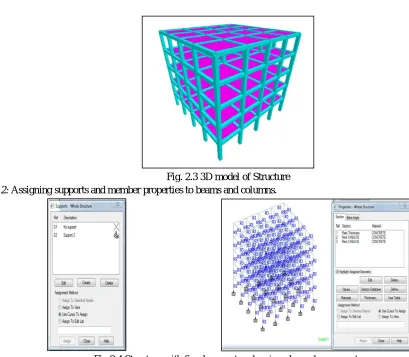
1) Step 1: Modelling of structure as per geometry.
Fig. 2.3 3D model of Structure
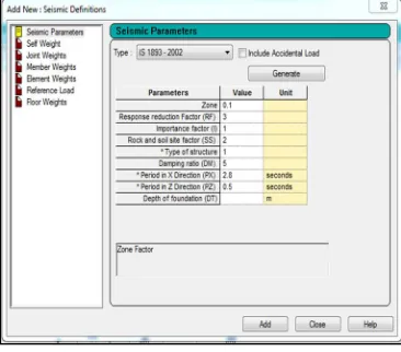
[image:5.612.78.487.116.473.2]2) Step 2: Assigning supports and member properties to beams and columns.
Fig.2.4 Structure with fixed support and assigned member property
3) Step 3: Assigning loads
Structure is analysed for following loadings:
a) Dead Load
b) Live Load
c) Seismic Load
[image:5.612.179.411.549.715.2]Dead load consists of self weight of structural member plus weight of walls.
©IJRASET: All Rights are Reserved
1207
[image:6.612.208.408.89.252.2]Residential building live load for analysis was taken as 3 KN/m2 as per IS 875 Part II
Fig. 2.6 Structure subjected to live load
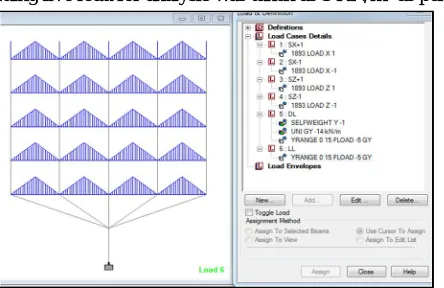
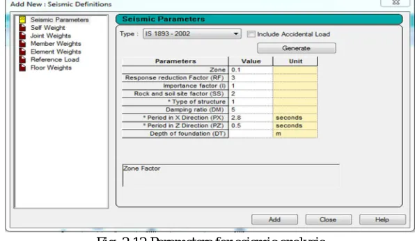
Static seismic load is calculated as per the guidelines of IS 1893:2002 by specifying parameters shown in fig.
Fig. 2.7 Parameters for seismic analysis
Seismic Loading Calculations(Lump weight
calculations):-i) Dead Load Calculations
Density of materials used: - I. Reinforced: 25 KN/m³
II. Flooring material (cm): 20 KN /m³ Total Weight of Slab = 0.15 x 16 x 16 x 25
= 960 KN
Total Weight of Column = 0.4 x 0.5 x 25 x 25 = 125.00 KN
Total weight of Wall = (weight of longitudinal walls + weight of traverse walls) x Height = (3.5 x 4.6 x 4 x 4 + 3.6 x 4.6 x 4 x 4) x 3=1564.68 KN
Total Dead Load on Intermediate Floor = 960 + (16 x 16 x 0.8) = 1164.80 KN
Total Dead Load per m2on Intermediate Floor = 2649.68/ (16 x 16)
= 10.35 KN /m2 Total Dead Load on Top Floor = 960 + (0.5 x 125) + (0.5 x 1564.68) = 1804.84 KN
Total Dead Load per m2on Top Floor = 1804.84 / (16 x 16) = 7.05 KN /m2
ii) Live Load Calculations
Total Live Load per m2on Intermediate Floor = 3 KN /m2
[image:6.612.214.397.288.449.2]©IJRASET: All Rights are Reserved
1208
= 11.85 KN /m2
Lump Weight on Top Floor =7.05 + 1.5
= 10.575 KN /m2
Loading Combinations are taken as per IS 1983:2002 clause No. 6.3.1.2
4) Step 4: Analysis of Building model Procedure of Analysis of Building model
In STAAD-Pro, building model were analyse for seismic loading by following way.
a) Modeling of Building
b) Member sizes
c) Support Specification
d) Application of loading
e) Analyses
f) Result report
E. Step by Step procedure of Static Equivalent Analysis in STAAD-Pro
For A Single-Column Structure
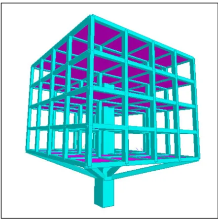
[image:7.612.195.416.489.711.2]1) Step 1: Modelling of structure as per geometry.
©IJRASET: All Rights are Reserved
1209
[image:8.612.180.434.90.243.2]2) Step 2: Assigning supports and member properties to beams and columns.
Fig. 2.9 Structure with fixed support and assigned member properties
3) Step 3: Assigning loads
Structure is analysed for following loadings:
a) Dead Load
b) Live Load
c) Seismic Load
[image:8.612.184.426.362.530.2]Dead load consists of self weight of structural member plus weight of walls.
Fig. 2.10 Structure subjected to dead load
Residential building live load for analysis was taken as 3 KN/m2 as per IS 875 Part II
[image:8.612.198.420.568.712.2]©IJRASET: All Rights are Reserved
1210
[image:9.612.155.453.93.266.2]Static seismic load is calculated as per the guidelines of IS 1893:2002 by specifying parameters shown in fig.
Fig. 2.12 Parameters for seismic analysis
Seismic Loading Calculations (Lump weight calculations)
i) Dead Load Calculations
Total Weight of Slab = 0.15 x 16 x 16 x 25 = 960 KN
Total Weight of Column = 0.4 x 0.5 x 25 x 25 = 125.00 KN
Total weight of Wall = (weight of longitudinal walls + weight of traverse walls) x Height = (3.5 x 4.6 x 4 x 4 + 3.6 x 4.6 x 4 x 4) x 3=1564.68 KN
Total Dead Load on Intermediate Floor = 960 + (16 x 16 x 0.8) = 1164.80 KN
Total Dead Load per m2on Intermediate Floor = 2649.68/ (16 x 16)
= 10.35 KN /m2 Total Dead Load on Top Floor = 960 + (0.5 x 125) + (0.5 x 1564.68) = 1804.84 KN
Total Dead Load per m2on Top Floor = 1804.84 / (16 x 16) = 7.05 KN /m2
ii) Live Load Calculations
Total Live Load per m2on Intermediate Floor = 3 KN /m2
Lump Weight on Intermediate Floor = D.L. + 0.5 L.L = 10.35 + 0.5 x 3
= 11.85 KN /m2
Lump Weight on Top Floor =7.05 + 1.5
= 10.575 KN /m2
4) Step 4: Analysis of Building model
a) Procedure Of Analysis Of Building Model: In STAAD-Pro, building model were analyse for seismic loading by following way.
i) Modeling of Building
ii) Member sizes
iii) Support Specification
iv) Application of loading
v) Analyses
vi) Result report
vii) Cost Estimation
©IJRASET: All Rights are Reserved
1211
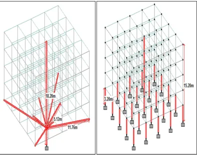
Fig 2.13: Single column and Multi column structure.
5) Calculation
a) For Multi-column Structure
Where, total nos. of column- 25 Size of column – 0.4m x 0.5m
Height of Column- 3.2m (Floor to Ground level)
Quantity of Concrete= 25 x 0.4 x 0.5 x 3.2 + 1 x 0.4 x 0.5 x 12 =18.4 m3(Y)
b) For Single Column Structure
Where,
Size of central column-1.8m x 1.8m - Height-18.2 - No. of column-01 Size of long inclined column-0.50 x 0.60m - Length-11.76m - No. of column-04 Size of short inclined column-0.50 x 0.60m - Length-5.12m - No. of column-04 Quantity of Concrete= (1x1.8x1.8x18.2) + (4x0.5x0.6x11.76) + (4x0.5x0.6x4) =77.88 m3(Y)
Cost comparison of RCC single column and RCC multi column can be done by just comparing the cost of columns which are highlighted in above figure. Volume of highlighted columns in single column structure is 5 times the volume of highlighted columns in multi column structure. If cost of multicolumn structure is X + Y then Cost of single column structure is X + 5Y. Where X = Cost of non highlighted part in structure which is same for both structures and Y = Cost of highlighted part in multi column structure. In general Construction cost of columns in a building is 10% of the total cost of building. But in Fig. 5 (multi column structure) as we are considering columns only up to first floor (excluding centre column), Construction cost of highlighted columns would be 5% of the total cost of building. If total cost of multi column structure is 100 i.e. X+Y = 100, Where X = 95 and Y = 5.
Then Cost of single column structure is X+5Y = 95+5(5) = 120
©IJRASET: All Rights are Reserved
1212
III.RESULT
A conventional multi-storey building & a single column building structure were analysing in STAAD-Pro and graphs were plotted for extreme corner column of building against the deflection and behaviour of columns studied. Result of deflection obtained from the software (Statics analysis method) was presented in table given below:-
A. Result Of Static Analysis For A Conventional Multi-Storey Building
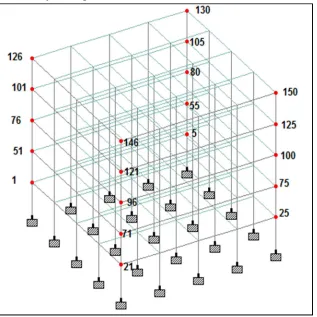
[image:11.612.150.467.166.483.2]1) Column Deflection for multi-storey building
[image:11.612.69.526.562.730.2]Fig.3.1 to show the all column node for multi-storey building
Table 4.1 Deflection of corner column node for multi- Table 4.2 Deflection of corner column node for multi- column building (A) column building (B)
Node COMBINATION
L/C
Horizontal Horizontal
X mm Z mm
1 L/C 6 0.322 -
L/C 7 - 7.551
51 L/C 6 0.445 -
L/C 7 - 7.698
76 L/C 6 0.742 -
L/C 7 - 8.155
101 L/C 6 1.065 -
L/C 7 - 8.623
126 L/C 6 1.378 -
L/C 7 - 9.098
Node COMBINATION
L/C
Horizontal Horizontal
X mm Z mm
25 L/C 6 0.095 -
L/C 7 - 1.776
75 L/C 6 0.151 -
L/C 7 - 1.807
100 L/C 6 0.210 -
L/C 7 - 1.931
125 L/C 6 0.274 -
L/C 7 - 2.054
150 L/C 6 0.341 -
©IJRASET: All Rights are Reserved
1213
Table 4.3 Deflection of corner column node for multi- Table 4.4 Deflection of corner column node for multi- column building (C) column building (D)
B. Result Of Static Analysis For A Single Column Building
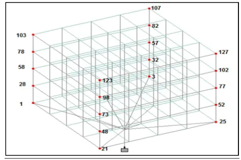
[image:12.612.186.423.326.483.2]1) Column Deflection for single column building
[image:12.612.43.522.556.725.2]Fig.3.2 to show the all column node for single column building
Table 4.5 Deflection of corner column node for single Table 4.6 Deflection of corner column node for single column building (A) column building (B)
Node COMBINATION
L/C
Horizontal Horizontal
X mm Z mm
21 L/C 6 0.308 -
L/C 7 - 6.007
48 L/C 6 0.591 -
L/C 7 - 6.124
73 L/C 6 0.746 -
L/C 7 - 6.488
98 L/C 6 0.072 -
L/C 7 - -0.058
123 L/C 6 1.107 -
L/C 7 - 7.238
Node COMBINATION
L/C
Horizontal Horizontal
X mm Z mm
5 L/C 6 0.407 -
L/C 7 - 2.302
55 L/C 6 0.471 -
L/C 7 - 2.423
80 L/C 6 0.532 -
L/C 7 - 2.538
105 L/C 6 0.586 -
L/C 7 - 2.646
130 L/C 6 0.633 -
L/C 7 - 2.747
Nod e
COMBINATION L/C
Horizontal Horizontal
X mm Z mm
21 L/C 6 0.322 -
L/C 7 - 7.551
71 L/C 6 0.445 -
L/C 7 - 7.698
96 L/C 6 0.742 -
L/C 7 - 8.155
121 L/C 6 1.065 -
L/C 7 - 8.623
146 L/C 6 1.378 -
L/C 7 - 9.098
Node COMBINATION
L/C
Horizontal Horizontal
X mm Z mm
3 L/C 6 0.305 -
L/C 7 - 6.389
32 L/C 6 0.484 -
L/C 7 - 6.5
57 L/C 6 0.674 -
L/C 7 - 6.945
82 L/C 6 0.879 -
L/C 7 - 7.39
107 L/C 6 1.092 -
©IJRASET: All Rights are Reserved
1214
Table 4.7 Deflection of corner column node for single Table 4.8 Deflection of corner column node for single column building (C) column building (D)
IV.CONCLUSION
Following conclusions can be drawn on the basis of analysis on a conventional multi-storey building & a Single column structural system:-
A. A conventional multi-storey building & a Single column structure has been designed successfully to withstand all loads including earthquake load.
B. Single column structure is 20 % more costly when compared with multi- column structure.
C. We may also check the deflection of various members under the given loading combinations.
D. The Result of deflection obtained from the software for a conventional multi-storey building & a single column building structure.
E. RCC column give satisfactory result under static loading condition.
F. Study the performance of lateral displacement at II zones when seismic load applied to the structure.
G. Storey drift in high rise structures are subjected to excessive deflection. Deflection obtained by STAAD-Pro is checked by IS
Codal limitation for serviceability. Base shear gives the base shears for entire structures.
H. STAAD-Pro advanced software which provides us a fast, efficient, easy to use and accurate platform for analyzing and designing structures.
This project has been selected with utmost enthusiasm and keen interest by me and has been successfully completed with our knowledge to our satisfaction. We have applied our gained knowledge during this project. A comparative study on analysis of a conventional multi-storey building & a single column building is analyzed with special attention and it is completed. Maximum space utilization is considered while planning and designing and we assure it will serve its maximum serviceability.
REFERENCES
[1] E K Mohanraj, S Nisar Ahmad, A Gowri Sankar, Kongu Engineering College, (2002)1 "Analysis and Design of an Office Building with Mono Column," PP.
27th Conference on Our World in Concrete & Structures.
[2] Venu Babu A, Et Al, (2016)2 "Design Of A Structure Supported On Single Column Office Building", International Journal Of Research Sciences And Advanced Engineering [IJRSAE] Volume 2, Issue 15, Pp: 112-123.
[3] Babicki, B.B.3 "Westcoast Building Cable Suspended Structures Vancouver, B.C." PP 1972, Zürich, Schweiz, Ethz Zurich Library. [4] Badikala Sravanthi, Dr. K.Rajasekhar, (2016)4 "Design Of A Structure Supported On Single Column", Pp In ISSN-2349-8439.
[5] Madireddy Satyanarayana, (2016)5 "Design of Multi Storey Building Resting On Single Column”IJRET Eissn: 2319-1163 | Pissn: 2321-7308.
[6] Donald MacLeod, Tom Mathie, Graham Dunlop, and Sean Duvall, (2011)6 “Innovative Mono-Column Support Structure "PP. at the SPE Offshore Europe Oil
and Gas Conference and Exhibition held in Aberdeen, UK...
[7] Janakkumar M. Mehta (2017)7 “In this study the (G+17) storey building was analyse with different shear-wall configuration”
[8] Pooja Liz Isaac et. al. (2017)8 “They found the Equivalent static and Response spectrum analysis of Diagrid, Hexagrid, Octagrid and Exterior Braced steel
building were performed.”
Node COMBINATION
L/C
Horizontal Horizontal
X mm Z mm
1 L/C 6 0.244 -
L/C 7 - 6.007
28 L/C 6 0.337 -
L/C 7 - 6.124
53 L/C 6 0.562 -
L/C 7 - 6.488
78 L/C 6 0.806 -
L/C 7 - 6.86
103 L/C 6 1.043 -
L/C 7 - 7.238
Node COMBINATION
L/C
Horizontal Horizontal
X mm Z mm
25 L/C 6 1.275 -
L/C 7 - 7.616
52 L/C 6 1.498 -
L/C 7 - 7.987
77 L/C 6 1.707 -
L/C 7 - 8.344
102 L/C 6 1.903 -
L/C 7 - 8.683
127 L/C 6 2.135 -
©IJRASET: All Rights are Reserved
1215
[9] Erik Hallebrand et. al. (2016)9 “For vertical and horizontal loads on a building, advantage can be taken to study each load-case separately. The forcedistributions and reaction forces due to vertical loading should be analysed without the consideration of floor diaphragms.”
[10] A. Braconi et. al., (2008)10 " Seismic performance of a 3D full-scale high-ductility steel–concrete composite moment-resisting structure—Part I: Design and
testing procedure" Published online in Inter Science Wiley.
[11] Dr. P. Suryanarayana (2010)11 “developed an approach large floor area can be economically constructed adopting steel framework of columns, girders and
flooring of reinforced concrete”.
[12] T. Andres Sanchez, M.S., E.I.T., Brad Davis, Ph.D., S.E., and Thomas M. Murray, Ph.D., P.E, (2011)12 "Floor Vibration Characteristics of Long Span Composite Slab Systems", Structures Congress © ASCE.
[13] Mahbuba Begum Robert G. Driver, M.ASCE and Alaa E. Elwi, M.ASCE, (2007)13 " Finite-Element Modeling of Partially Encased Composite Columns Using
the Dynamic Explicit Method", Journal Of Structural Engineering © ASCE.
[14] Dr. D. R. Panchal, (2014)14 “Advanced Design of Composite Steel-Concrete Structural element" Pp in ISSN - 2248-9622, Vol. 4, Issue 7 (Version 2).
[15] Morita, K., Keii, M. And Matsumoto. S, (2011)15 "Applications of high performance structural steels to high-rise steel buildings” the 6th international