Design and Analysis of an Index Able Seat of Car
for Adults and Children
Prof. Shrikant. T. Jagtap1, Dr. Shrikant. P. Kallurkar2, Sonali A. Randive3
1
Punyashlok Ahilyadevi Holkar Solapur University, India, 2Mumbai University,India
3
Punyashlok Ahilyadevi Holkar Solapur University, India
Abstract: Child restraint systems are used to reduce the injuries to children during accidents. These systems are not integral part of the car seating system but are separately made available & need to be fixed in the cars as & when required. Again there are issues of correct installation of these systems, stringent or lenient laws related to child safety in different countries. In this research work, an effort is made to design a rear car seat which will be useful for both children & adults. The arrangement eliminates separate use of boosters on the back side & also on the seat. The seat is of indexable/convertible type so that when adult person is travelling, he/she can use it in normal position. But, when a child is to use the seat, indexing of the seat will make it a child seat with booster on seat. Forward movement of the seat eliminates the use of back booster. Manufacturing of the above seat is done after confirming the dimensions by Finite Element Analysis done using ANSYS software.
Keywords:CRS, Rear seat, Child safety, indexable, ANSYS
I. INTRODUCTION
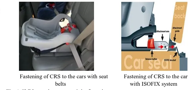
Child restraint systems are designed specifically to protect children from injuries or death in case of car collision. The use of CRS is legally prescribed in many countries and usually these seats are bought and installed in cars by consumers.
A. Child Restraint Systems
Typical Child Restraint System
Fastening of CRS to the cars with seat belts
Fastening of CRS to the cars with ISOFIX system Fig. 1 Child restraint systems & its fastening to cars
[image:1.612.197.524.397.554.2]B. Safety Belts Fixation in Car
The seat belt ends are fixed to the various positions as shown in Fig.2.
In case of the cross belt (inclined one), one end is fixed to the car body on the lower side. Second end is fixed to the car body to the upper side near the door. In the horizontal belt, the ends are fixed to the structure or body of the car on either side of the seat. Thus it is observed that instead of adults, if a child is sitting in the same seat, the height of the seat should be increased & also the back rest portion of the seat should be taken ahead to have the correct positioning of the seat belts. Presently back boosters for back rest part & also on the seat boosters are provided as shown in Fig. 3.
Backless booster [1] [2] High back booster
Fig. 3 Booster types
II. PROBLEMIDENTIFICATION
A. In India laws related to child safety are lenient. Hence, people are not using it. In addition, due to emotions, they carry the
children along with them without any seat belts leading to unsafe journey.
B. It is troublesome to carry the CRS & correctly install it every time.
C. Thus need of a convertible/indexable rear car seat is there which will motivate people to go for child safety.
III.THEPROPOSEDREARCARSEATSYSTEM
[image:2.612.139.484.428.715.2]The proposed system consists of various parts as shown in Fig. 4.
A. Arrangement In Seat Replacing Back-Booster Of Restraint System
Here the complete seat (horizontal seat & back rest both as a single unit) can be taken to any forward position by sliding it in the ‘C’ channels & then it can be locked in that position. The rectangular tube which acts as guide for this movement is shown below in Fig. 5. The two locking pins are also seen in the Fig. 5.
[image:3.612.177.450.179.360.2]The locking arrangement is spring operated. It consists of two springs & two pins. To release the lock, pull the horizontal plate so that springs will get compresses. After adjusting the position release the spring. This will automatically engage the pins in the holes & will lock the seat in that position. The arrangement is shown in RED color in the Fig.s 4& 5.
Fig. 5 Arrangement for seat forward & backward movement & indexing
Fig. 6 Details of the locking arrangement for sliding movement & indexing movement
[image:3.612.159.470.405.608.2]Seat in the normal position Seat taken to forward side
Fig. 7 Backward & Forward movement of the complete seat B. Convertible/Indexable Arrangement for Children
[image:4.612.115.287.354.472.2]Here the horizontal seat part is rotated about a central hinge point/pin to bring the lower part of seat (which is made for child i.e. with height booster) to the upper side. For this first it should be first unlocked by pulling the plate leading to compression of spring. After indexing, the seat can now be locked by leaving the plate/strip so that the spring will come to its original position & the two pins will engage the two holes. The arrangement is shown in GREEN color in Fig. 4, 6 & 7.Position of the locking arrangement: Proposed design is supposed to be used for rear seat of left or right. It is proposed to keep the locking arrangements on the outer side of the seat. i.e. to the door side.
Fig. 8 Indexing/conversion of seat
IV.DESIGNOFNEWPARTSOFPROPOSEDREARCARSEAT
A. Design of Hinge Pin for The Seat
Let maximum mass of a person sitting on the rear car seat as 100 kg. Let Factor of Safety = 3
Let the material of the pin be steel with 0.65 % Carbon, 0.5 to 0.8 % Mn. …….[5]
Yield stress of the above steel =yield = 430MPa
Shear strength of the mild steel = = 0.5 x yield = 0.5 x 430 = 215MPa
As there are two pins on two sides of the seat, load will be shared by pins. Load one pin = 0.5 x 100 x 9.81 x 3 = 1471.5 N
Considering shear failure of pin,
= = = 125 ;Solving, d = 2.95 mm = 3 mm
A pin of 5 mm may be taken as a standard one.
Seat taken to forward side instead of back side booster
B. Design of Rectangular Guide Tubes These are rectangular tubes of mild steel.
As there are four legs at four corners, on one side two legs will be there. The distance between the legs is 500 mm.
[image:5.612.195.427.144.232.2]Thus it is a case of a beam with two ends fixed & uniformly distributed load.
Fig. 9 Cantilever beam with uniformly distributed load
For the above case deflection is given by
= ……… here ‘w’ is load per unit length
The above equation can be written as
= …………. Where ‘W’ is total load.
Let the deflection of the guide tube at the centre be 0.1 mm for 300 kg load. Hence
= = 0.1
I = 22809.7 mm4
Considering the rectangular tubes, available in market, a tube with 25 mm (vertical side) x 38 mm (horizontal side) with thickness of 2 mm is tried here.
Moment of Inertia = - = - = 23239.6 mm4
As 23239.6 >22809.7, the tube chosen is found ok.
C. Design of Springs
Two springs are used for locking the forward movement of the seat. Here the locking needed is string & whole seat is remaining at the rest with only two pins which are held by these springs. But in case of indexing of the seat, the seat has two hinge or index pins & two more pins are of locking system. Here two hinge pins are always supporting vertical load of person sitting on seat. Here only one spring is sufficient to hold the two pins of the locking system.
Let Spring index C = D/d = 10
Wahl’s Stress Concentration Factor K = = 1.098
Let us take a material Carbon Steel with 420 MPa as allowable shear stress (fs), Modulus of rigidity as 80 x 103MPa&
Modulus of Elasticity as 2.1 x 10⁵MPa.……….[4]
Let the maximum force to be applied is 50 N as this is very low force & can be applied easily by human being.
fs = K x ;420 = 1.098 x ;d =1.82 mm = 2 mm (Say)
Hence, Coil diameter D = 10 x 2 = 20 mm
Let us check deflection for certain number of coils. Let number of turns = 5, Then,
= = = 12.5 mm
D. Design of Legs for The Seat
The four legs at four corners will be under compressive load.
Considering a circular tube of 25 mm diameter & 0.5 mm thickness, let us check the buckling strength of the legs The legs will be having fixed ends. These will be of mild steel.
Fig. 10 End columns taking complete load of upper frames and lower frames
Total load = 3x100 x 9.81 = 2943 N Load on each tube =2943/4 = 735.75 N
Checking for L/r ratio to decide the formula to be used for checking the buckling of the column (leg). Here L = Length of column & r = Least radius of gyration
L =235 mm
Let thickness of tube is equal to 0.5 mm.
The above thickness is chosen taking into consideration the welding of the component. The columns of still smaller thickness will not sustain the temperature during melting and welding will not be proper.
r = = = 8.67
Hence L/r = 235/8.67 = 27.1
As L/r ratio is less than 120 & material of the legs is mild steel, using Johnson’s Parabolic formula,
Critical buckling load Pc = a y where
Here,
a = Area of cross section a = 252 -242 = 49 mm2
y = yield stress y = 250 MPa
n = coefficient of end condition n = 4 as both ends of the legs are fixed
E = young’s modulus R =Least radius of gyration L =Length of column L/r = 27.1
Hence,
Pc = 49 x 250 x = 11980.5 N
Thus critical buckling load is much larger than the requirement. Hence tube i.e. legs are safe from failure point of view.
Let us check deflection (axial) due to compression.
= = = 0.0672 mm
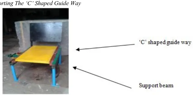
E. Design of Beam for Supporting The ‘C’ Shaped Guide Way
Fig. 11 Beam for supporting the ‘C’ shaped guide way
Considering the two sides of the seat, the load will be 150 kg on one side. Here a supporting beam is used between the legs. On this beam the ‘C’ shaped guide way is mounted. Thus load will be transferred to beam at the end. Here, this beam is fixed at both the ends & the load is distributed along the length of the beam.
Here load is 150 x 9.81 =1471.5 N Length of beam is 500 mm.
= …………. Where ‘W’ is total load.
Let the deflection of the guide tube at the centre be 0.1 mm.
= = 0.1 ;I = 22809.7 mm4
Here a square tube with 25 mm sides can be taken.
Let us determine, the thickness of the tube having at least above value of moment of inertia.
Outer Side = b1 , Inner side = b2
Moment of inertia I = (b14- b24)/12 = (304 - b24)/12 = 22809.7
After solving b2= 27.06 mm
Thus a square tube of 30 mm side & thickness 1.5 mm is sufficient for this beam.
V. FINITEELEMENTANALYSISOFPARTOFNEWREARSEAT
Fig. 12 Geometry of SOLID45 element [10]
The tetrahedral option is used for this model. Solid 45 is used for the 3-D modeling of solid structures. The element is defined by eight nodes having three degrees of freedom at each node: translations in the nodal x, y, and z directions. The element has plasticity, creep, swelling, stress stiffening, large deflection, and large strain capabilities.
Following table shows variation of element edge length & the deformation of the leg under axial loading.
TABLE I
Deformations for various edge lengths
Element Edge length Deformation Element Edge
length
Deformati on
4 mm 0.113966 5.5 mm 0.109785
4.5 mm 0.107784 6.0 mm 0.112652
5 mm 0.113981 7.0 mm 0.113833
Analytical value of deformation of the leg is determined using the formula = PL/(AE)
The analytical value of deformation is 0.1141 mm. As error is only 0.1 % for 5 mm size, the same is finalized here for further work. Fig. 13shows model & deformation of the leg under the applied load.
Meshed model with load & boundary condition Deformation of the leg
Fig. 13 Model of leg, boundary condition & load condition
Considering the above table, an element edge length of 5 mm is found to be suitable for this structure. The number of nodes is 1574 & number of elements is 4646.
[image:8.612.93.496.337.518.2] [image:8.612.81.483.570.720.2]Fig. 14 Meshed model of legs with beam mounted on it
[image:9.612.337.508.154.319.2]Fig. 15 Boundary conditions applied at bottom of the legs
Fig. 15 shows boundary conditions applied to the bottom of the legs. Here all motions rotary & linear are restricted. Fig. 16 shows pressure applied on the upper side of the beam.
Pressure =Force/area = 150 x 9.81 / (30 x 500) = 0.0981 MPa
[image:9.612.84.260.158.318.2]Fig. 16 Pressure applied on beam supported on legs Fig. 17 Deformed shape of the structure
Fig. 18 shows the stresses developed in the structure.
Fig. 18 Von Mises stresses in the structure
The maximum deformation is 0.31597 mm & maximum stress is 81.248 MPa. The stresses & deformation are found to be within limit.
As above is not a standard case, comparison of results is done only for leg deformation. Following table shows results of deformation of legs.
TABLE 2 DEFORMATION OF LEG
Analytical deformation Deformation (ANSYS) % Error
0.1141 mm 0.113981 mm 0.1
VI.CONCLUSIONS
A. The The proposed design of car rear seat facilitates use of seat for both children or for adults easily.
B. Due to this type of seat arrangement, there is no need of carry CRS separately.
C. Due to the proposed car rear seat design, people will get motivated to take care of safety of their children.
[image:9.612.209.406.361.519.2]E. The proposed design reduces some luggage space below the seat.
F. Finite element analysis results indicate that the dimensions finalized are ok.
REFERENCES
[1] Karin Brolin, Isabelle Stockman, Marianne Andersson, Katarina Bohman, Laure-Lise Gras, LottaJakobsson, Safety of children in cars: A review of biomechanical aspects and human body models, IATSS Research, ,(2015)
[2] Lotta Jakobsson, Katarina Bohman, Marianne Andersson, Isabelle Stockman, Ola Boström, Mats Svensson, Henrik Svanberg, Maria Wimmerstedt, Kristy B. Arbogast, Rear seat safety in frontal to side impacts – focusing on occupants from 3yrs to small adults, Paper Number 11-0257,
[3] Dr. R. K. Bansal, A Textbook of Strength of Materials, Laxmi Publications (P) Ltd., New Delhi, 2014 [4] R.S. Khurmi & J. K. Gupta, A Textbook of Machine Design, Eurasia Pub. House P. Ltd., New Delhi, 2015 [5] Joseph Edward Shigley, Mechanical Engineering Design, McGraw Hill, 2009
[6] M. F. Spotts, Design of Machine Elements, Prentice Hall of India Pvt. Ltd, New Delhi, 2013 [7] Reddy J.N. , An Introduction to Finite Element Method, Tata McGraw-Hill Publication, 2012
[8] Tirupati Chandrupatla, Ashok Belegundu, Introduction to Finite Elements in Engineering, Prentice Hall India, 2014 [9] PSG Design Data Handbook, 2010


![Fig. 12 Geometry of SOLID45 element [10] The tetrahedral option is used for this model](https://thumb-us.123doks.com/thumbv2/123dok_us/1245104.650853/8.612.81.483.570.720/fig-geometry-solid-element-tetrahedral-option-used-model.webp)

