Smart Blind Stick
Shreya Jaiswal1, Mr. Brijesh Kumar Dubey2, Mr. Amit Sharma3
1, 2
Department of Electrical and Electronics Engineering PSIT, Kanpur, Uttar Pradesh
3
Assistant professor Department of Electrical and Electronics Engineering PSIT, Kanpur
Abstract: This is a smart stick for blind person who are not much confident in moving alone with the lay stick. We provide some sensors, wheels, programing to this lay stick . These are normal things but arranged in a proper ly such that it gives an outcome which is the honeydew for blind person. This is a smart solution for those people who are blind since from the birth and those who lost their eyes in an accident.
Keywords: Blind stick; ATmega328 microcontroller; ultrasonic; Dc motor; water sensors; GPS; GSM .
I. INTRODUCTION
[image:1.612.201.415.321.442.2]The smart blind stick automatically detects the obstacle in front of the person and give him a response to the person by the beep sound which is attached to the stick. Through this, the blind person can aware about the obstacles in front of him. I used Ultrasonic sensor for detecting the obstacles, GPS is used to track the position of the person, temperature sensor is used to sense the fire near by at a particular distance.
Fig 1 Schematics diagram of smart blind stick
II. SYSTEM DESCRIPTION
[image:1.612.205.420.460.650.2]A. Arduino Uno
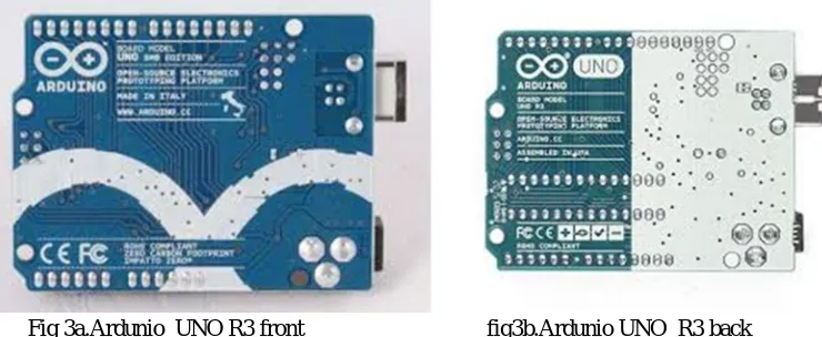
[image:2.612.131.501.148.300.2]The Arduino Uno is a microcontroller board It is based on the ATmega328 . It Consists of 14 digital input/output pins , 6 analog inputs, a 16 MHz ceramic resonator, a USB connection, a reset button ,a power jack, and an ICSP header. It needed to support the microcontroller; and simply connect it to a computer with a USB cable or power and it contain with a AC-to-DC adapter or battery to get started.
Fig 3a.Ardunio UNO R3 front fig3b.Ardunio UNO R3 back
B. Ultrasonic Sensor
The range of the Ultrasonic sensor HC - SR04 is 2cm - 400cm non-contact measurement function, and the accuracy can reach to 3mm. The modules contain three parts that is receiver ,ultrasonic transmitters, and control circuit. The basic working principle of ultrasonic sensor:
1) I am using I/O trigger for at least 10us high level signal,
2) TheHC-SR04Module automatically sends e 40 kHz and detect it is a pulse signal back.
3) If the signal back, through high level , time of high output. I/O duration is the time from sending ultrasonic to returning.
Fig 4 Ultrasonic sensor HC-SR04
C. Temperature Sesnor
[image:2.612.262.390.625.694.2]This temperature sensor is used to sense the fire near by at a particular distance. From the blind stick . This sensor is set to a particular temperature whenever it meets the condition it will beep and alert the person. This types of temperature sensor varies from simple ON and OFF thermostatic devices.
D. Water Sensor
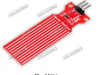
[image:3.612.220.400.155.286.2]This sensor is used to sense the water in the hole or in the pit which alerts the person that he might get slip into this pit and any accident can be happen. Water sensor brick is used to designed for water detection, which can be widely used in sensing the water level ,rainfall, , and even the liquate leakage. The brick is mainly comprised of three parts: It is a connector, of 1 MΩ resistor, and several lines of bare conducting wires.
Fig 6 Water sensor
E. GPS
[image:3.612.204.410.375.520.2]It is a process used to establish a position at any point on the globe. The Global Positioning System (GPS), originally Navstar GPS. It is a satellite-based radio navigation system which is operated by the United States Air Force. It is a global navigation satellite system that provides exact location and time information to a GPS receiver anywhere or near the Earth. Some Obstacles are mountains and buildings block the relatively weak GPS signals.
Fig 7 GPS
F. GSM
GSM is a cellular network, it means that cell phones are connect to it by searching for cell network. There are five different cell sizes in a GSM network—femto , pico ,macro, micro, and umbrella cells. The coverage area of each cell varies according to the implementation environment. Macro cells can be regarded as cells where the base station antenna is installed on a building above average rooftop level.
[image:3.612.252.407.624.709.2]G. Buzzer
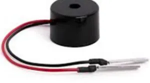
[image:4.612.243.393.148.231.2]A buzzer or beeper is an audio signaling device . There are so many types of buzzer and we will use piezoelectric buzzer which is activated from the microcontroller electrical circuit. It will alert the blind person from the object which is nearer to them.
Fig 9 piezoelectric buzzer
H. Jockey
It is used to move the stick with the help of wheel to move the stick in the forward and backward direction and also move left and right to find the path.
III. FUNCTIONAL DESCRIPTION
A. Ultrasonic Sensor
HC-SRC04 ultrasonic sensor has 4 pins-ground, VCC, trigger and Echo. It has two eyes –one is the transmitter which is used to transmit the signal and another one is the receiver which is used to receive the signal. Ultrasonic waves or ultrasound waves are the terms used to describe elastic waves with frequency greater than 20,000 Hz and normally exist in liquids, solids, , and gases. An ultrasonic wave moves at a velocity 3*10^8 m/sec that is determined by the material properties and shape of the medium.
B. GSM
A GSM is a Global System for Mobile communication module. It is a specialized type of module which accepts a Subscriber Identity Module( SIM )card, and operates over a subscription to a mobile operator. When a GSM module is connected to a microcontroller (ATmega328), this allows the microcontroller to use the GSM module to communicate over the mobile network. A GSM module exposes an interface that allows applications to send and receive messages over the module interface.
C. GPS
The GPS does not require to transmit any data, and it operates independently of any telephonic or internet reception, and these technologies can enhance the use fullness of the GPS positioning information. The GPS provides critical positioning capabilities to military, civil commercial users, and civil etc. around the world. The United States government created the system, maintains it, and makes it freely accessible to with a GPS receiver. The GPS project was launched in 1973 by the U.S. Department of Defense which is use by the United States military and became fully operational in 1995. It was allowed for civilian use in the 1980s.
D. Microcontroller (ATmega328)
An ATmega328, has 14 digital input/ output pins (of which 6 can be used as PWM (Pulse Width Modulation) outputs), six analog inputs with one 16 MHz crystal oscillator. For Communication purposes it has a number of facilities for communicating with a computer, or with other microcontrollers. The ATmega328 provides UART TTL serial communication which is available on digital pins 0(RX) and 1(TX).
IV. CONCLUSION AND DISCUSSION
parts, gathering all information about all the components of the system and from where should to buy these components and taking all precautions so that none of our components got damaged by inappropriate usage. We have searched lots of sites and visited to many faculty for the information and some seniors too. While drilling through these process we all get much updated about many components some are part of the system and some are not the part of the system. Sometimes we swirled about the topic(components) but we didn’t lose hope and keep trying to make our way, what exactly we want to make .So overall it was a good project and all team members equally contributed their efforts in this project.
REFERENCES
[1] Smart blind stick - an electronic approach to assist visually disabled persons Mohammad Hazzaz Mahmud, RanaSaha, Sayemul Islam
[2] MohdHelmyAbdWahab, Amirul A. Talib, Herdawatie A. Kadir, Ayob Johari, A. Noraziah, Roslina M. Sidek, Ariffin A. “Smart cane: assistive cane for visually impaired people”, IJCSI, Vol.8 Issue 4, July 2011.
[3] M. Bousbia-Salah, A. Larbi, and M. Bedda, “An approach for the measurement of distance travelled by blind and visually impaired people,” in Proc. 10th IEEE International Conference on Electronics, Circuits and Systems, Sharjah, United Arab Emirates, pp. 1312-1315, 2003.
[4] Hashino, S.; Ghurchian, R.; A blind guidance system for street crossings based on ultrasonic sensors. Information and Automation (ICIA), 2010 IEEE International Conference on June 2010
[5] David Castells, Joao M.F. Rodrigues, J.M. Hans du Buf “Obstacle detection and avoidance on sidewalks” In Proc. Int. Conf. on Computer Vision-Theory and Applications, Vol. 2, pp. 235-240, 201