Design and Analysis of
Arch-Type Pedestrian
Bridge Structure at different Element Sections
using Ansys
Rahul Nagdiya1, Prof. Sumit Pahwa2
1
M.Tech. Student, 2Associate Professor, Department of Civil Engineering, AIT, Ujjain (M.P.), India
Abstract: The objective of the research study is to model Arch bridge with two different design i.e. simple arch bridge and arch bridge with truss structure, using ANSYS software and to perform a modal analysis of bridge problem. For every one of the four materials eight node solid component is chosen and cross section is done exclusively for every modal. The material property of each material is selected as per literature database in ANSYS software. The modal analysis and design of bridge in ANSYS is analyse to find the natural frequency, deformations, stresses and mode shapes of bridge to avoid the resonance of the bridge. optimize cable and bridge deformations with comparison of simple arch bridge and arch bridge with truss structure.
Keywords: arch bridge, Truss structure, deformation, Finite element modelling, Ansys.
I. INTRODUCTION
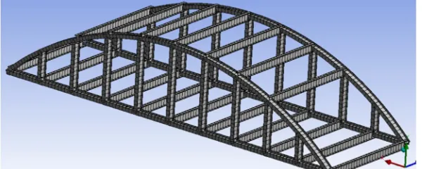
[image:1.612.158.458.592.712.2]In this study, the instructions and actions used to describe these models were remarkably like, even for various bridges. A truss component is a two-strength element that is subjected to axial loads either tensile or compression. The only 1D for a truss (bar) component is axial movement at each node. The cross-sectional area and material behaviours of each part are typically assumed constant with its length. The element can interrelate in a two-dimensional (2-D) or three dimensional (3-D) configurations. Truss elements are usually utilized in investigation of truss structures. A bridge is a structure that crosses over a gorge, street, river, railway, or other obstructions, permitting smooth and secure passage of cars, trains and pedestrians. A pedestrian railway bridge is a connection planned for pedestrians and in a few instances’ cyclists, animal site visitors and horse riders, instead of vehicular passage. Pedestrian bridges set off the scenery and may be used decoratively to visually hyperlink wonderful areas or to indication a transaction. In many evolved nations, pedestrian bridges are each functional and can be stunning works of art and sculpture. Nowadays, the analysis of truss is concerned of many designers and consultants. The truss structures are required to be designed in such a way that they have enough strength and rigidity to satisfy the strength and serviceability limitation. In order to archive the minimum requirement, it is necessary to carry out an accurate analysis to investigate the reaction and stress that acting inside the member of the truss. When the load acting on a truss, the structure may deform and change to different shape or size. The bridges are the structures, which provide means of communication over a gap and they provide passage for the highway and railway traffic over these gaps. There are several classifications of bridges based on different considerations. Some of the major classifications are based on: material used, makeup of main load carrying elements, the structural layout of the principal load carrying members, floor location, type of connections, the level of crossing of highway and railway track and the nature of connections, the level of crossing of highway and railway track and the nature of movement of the bridge. The present analytical study is limited to only steel truss bridges, in particular truss portion.
II. FINITE ELEMENT ANALYSIS
Experimental Truss bridge structure was analyzed by with ANSYS that is associate with engineering simulation commercially used software package providing a complete group that extents the complete variety of physics, offering right to use to almost several field of engineering replications that a design method needs. The software package use it’s tools to place a virtual product through a rigorous testing procedure like testing a beam below totally different loading circumstances before it turns into a considerable object. ANSYS will perform advanced engineering analyses quickly, safely and much by kind of contact algorithms, time based mostly loading options and nonlinear material models. During this study it familiar with carry out distinct modeling of Truss bridge structure investigates it below static loading conditions.
III. MODELLING OF BRIDGE STRUCTURE
A. Geometry of Sections
Two types of bridge structure design here, ‘I’ section and ‘L’ section used to designed bridge. Firstly, bridge designed by using ‘I’ section beam and then second bridge designed by using ‘L’ section of beam. Geometry of ‘I’ section and ‘L’ section are described below. Structural steel used as material for designing of bridge structure.
Figure 2: Dimensions of ‘I’ Section Figure 3: Dimensions of ‘L’ section
‘I’ section beam designed in two different designs, Truss Type ‘A’ and Truss Type ‘B’. ‘L’ Section Bridge designed in two different designs, Truss ‘A’ and Truss ‘B’.
B. Dimensions of Bridge Truss
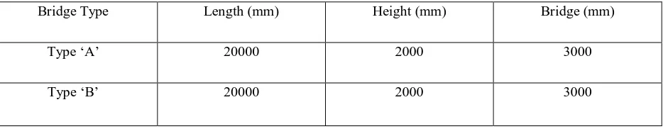
[image:2.612.65.532.631.722.2]Dimensions of bridge structure are described below.
Table 1: dimensions of bridge truss structure
C. ‘I’ Section Bridge
[image:3.612.99.515.117.275.2]Bridge truss designed using ‘I’ section of two types, Truss Type ‘A’ and Truss Type ‘B’. Figure shows the design of ‘I’ Section Bridge.
Figure 4: ‘I’ Section Bridge of Type ‘A’ Figure 5: ‘I’ Section Bridge of Type ‘B’
D. ‘L’ Section Bridge
[image:3.612.91.520.323.460.2]Bridge truss designed using ‘L’ section of two types, Truss Type ‘A’ and Truss Type ‘B’. Figure shows the design of ‘I’ Section Bridge.
Figure 6: ‘L’ Section Bridge of Type ‘A’ Figure 7: ‘L’ Section Bridge of Type ‘B’
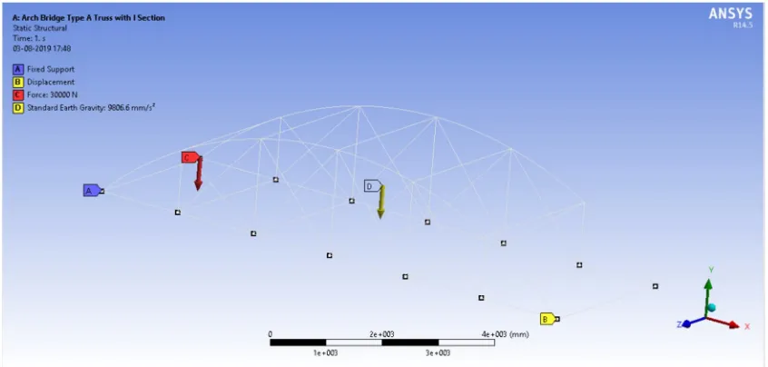
E. Applying Boundary Conditions
Applying boundary conditions on bridge, one end of bridge kept fixed support and, on another end, applying 30000 N load. In Type ‘A’ and Type ‘B’ bridge structure.
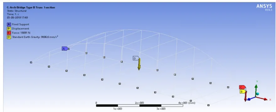
[image:3.612.106.529.512.714.2]Figure 9: Applying Boundary conditions on Type ‘B’ Bridge Structure.
IV. TEST RESULTS AND DISCUSSION
The deflection occurred in bridge structure model is optimized and compared. Two types of section used in bridge element designing i.e. ‘I’ section and ‘L’ section. In ‘I’ section two type of bridge structure used for study i.e. Type ‘A’ which is bridge truss design used and Type ‘B’ simple design of arch bridge also in ‘L’ section two section two type of bridge structure used for investigation i.e. type ‘A’ and Type ‘B’. Figure shows the deflection.
[image:4.612.125.514.371.528.2]A. Deflections Of Bridge Structure Due To Load
[image:4.612.121.519.557.705.2]Figure 10: ‘I’ Section Bridge Truss Type ‘A’ deformation
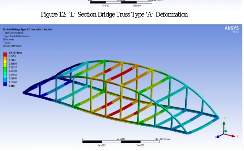
Figure 12: ‘L’ Section Bridge Truss Type ‘A’ Deformation
Figure 13: ‘L’ Section Bridge Truss Type ‘B’ Deformation
[image:5.612.130.483.552.717.2]Table shows the values of deformation developed in bridge truss structure due to load, and direct stresses generate in bridge structure.
Table 2: Arc Bridge Structure Type ‘A’ Analysis Results
Parameters
Bridge Type A Bridge Type B I Section L section I Section L section Total
deflections (mm)
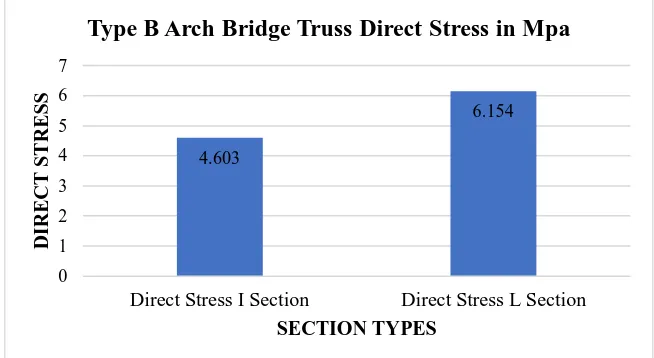
0.8 1.244 1.074 1.435 Direct Stress
(MPa) 5.637 7.698 4.603 6.154 Maximum
Combined Stress (MPa)
Figure: Deflections in Arch Bridge Structure Type A
Figure: Direct Stresses in Arch Bridge Structure Type A
Figure: Figure: Deflections in Arch Bridge Structure Type B
0.8 1.244 0 0.2 0.4 0.6 0.8 1 1.2 1.4
Total Deflections in I Section Total Deflections in L Section TO TA L D EF LEC TI O N S SECTION TYPES
Type A Arch Bridge Truss Deflection in mm
5.637 7.698 0 1 2 3 4 5 6 7 8 9
Direct Stress I Section Direct Stress L Section
D IR EC T S TR ES S SECTION TYPES
Type A Arch Bridge Direct Stress Mpa
1.074 1.435 0 0.2 0.4 0.6 0.8 1 1.2 1.4 1.6
Total Deflections in I Section Total Deflections in L Section
TO TA L D EF LEC TI O N S SECTION TYPES
Figure: Direct Stresses in Arch Bridge Structure Type B Table 3: Arch Bridge Type ‘A’ Deflections Due to Frequency Arch Bridge Type ‘A’ with I Section
Arch Bridge Type ‘A’ with L Section
Modes Frequency in Hz Type A
Deflections Type A
Frequency in Hz Type A
Deflections Type A 1 5.226 0.71 2.0622 1.042 2 15.686 0.757 6.7152 1.357 3 22.73 0.749 12.829 1.592 4 23.241 0.635 15.093 1.279 5 31.028 0.849 20.171 1.869 6 38.191 0.266 22.869 1.314
Table 4: Arch Bridge Type ‘B’ Deflections Due to Frequency
Arch Bridge Type ‘B’ with I Section Arch Bridge Type ‘B’ with L Section Modes Frequency in Hz
Type B
Deflections Type B
Frequency in Hz Type B
Deflections Type B 1 5.8176 0.748 5.8176 0.748 2 10.934 0.81 10.934 0.81 3 13.068 1.019 13.068 1.019 4 15.08 0.991 15.08 0.991 5 17.378 0.88 17.378 0.88 6 18.12 1.109 18.12 1.109
V. CONCLUSION
The ANSYS analysis for this steel truss is done based on the standard loading system, and the results are within the limited preconditions sated by the standard value.
From this study we can conclude the ANSYS analysis for this truss is very perceptive. The study has shown the possibility of analysis and design of Arch Truss bridges structure with locally available steel profiles. Even though the cost of local production is closer to importing it is still a good option since it helps in the capacity building of local design, fabrication and construction firms, creates job opportunities for many people and is a saving in foreign currency. For many short span temporary bridges in road construction projects. 4.603 6.154 0 1 2 3 4 5 6 7
Direct Stress I Section Direct Stress L Section
D IR EC T S TR ES S SECTION TYPES
A. As per above study, it is concluded that ‘L’ section Arc bridge structure having more deflection in comparison of ‘I’ section therefore ‘I’ section suitable and acceptable for designing of Bridge truss structure.
B. In Comparison of Truss Type A and B, we found in analysis that arch bridge structure with Type ‘A’ having minimum deflection in both ‘I’ and ‘L’ section as comparison to Type ‘B’ Truss structure.
C. It shows as per above study that Arch bridge structure with type ‘A’ using I section gives better stability than section ‘L’.
VI. SCOPE OF FUTURE WORK
A. Design different Bridge truss structure using ‘C’ Section and compare that with ‘I’ and ‘L’ Bridge structure.
B. Using various types of truss structure.
REFERENCES
[1] Rohit Gakre, Rashmi Sakalle, Nitin Tiwari,"Analysis of Railway Bridge Steel Sections with Different Type of Trusses for 32.5 Tonne Axle Loading", International Journal for Research in Applied Science & Engineering Technology, Volume 6 Issue XI, Nov 2018.
[2] Y Q Cai, W S Ding, "Mechanical Behavior Analysis of Long-span Steel Truss Arch Bridge Based on Static Load Test",Materials Science and Engineering, 2018.
[3] Yong-sheng Song, You-liang Ding, Han-wei Zhao, "Structural behavior analysis of a continuous steel truss arch railway bridge integrating monitoring data", Advances in Mechanical Engineering, Vol. 9, 2017.
[4] Wei He, Yinqiao Zhu, Renlong Chen, "Brief research on arch hinge of the steel truss arch bridge by contact problem under local stress", 3rd International Conference on Advances in Energy, Environment and Chemical Engineering, Earth and Environmental Science, 2017.
[5] CHEN Shuli, SU Mubiao,LIU Yuhong, WANG Qingmin "Vibration Remote Monitoring System of Continuous Steel Truss girder for the Wuhu Yangtze River Bridge", 14th World Conference on Earthquake Engineering, October 12-17, 2008, Beijing, China.
[6] Darius Bačinskasa, Arvydas Rimkusa,b,*, Deividas Rumšysa , Adas Meškėnasa,"Structural analysis of GFRP truss bridge model", Modern Building Materials, Structures and Techniques, Procedia Engineering 172, Elsevier, 2017, PP. 68 – 74.
[7] E. Yamaguchi, R. Okamoto, K. Yamada "Post-Member-Failure Analysis Method of Steel Truss Bridge", The Twelfth East Asia-Pacific Conference on Structural Engineering and Construction, Elsevier, 2011.
[8] Md. Emdadul Hoque, Shaikh Sumit Noor, Oishwarjya Ferdous,"An Investigation Of The Behavior Of Mechanical Structures Due To Vibration Using ANSYS", Proceedings of the International Conference on Mechanical Engineering and Renewable Energy, 2017.
[9] F. Masoumi, A. Mehrabzadeh, "Application of Influence Lines on Static Analysis of Cable-Stayed Bridges", IACSIT International Journal of Engineering and Technology, Vol. 5, No. 6, December 2013.
[10] Huili Wang, Hao Gao, Sifeng Qin, "Fatigue Performance Analysis and Experimental Study of Steel Trusses Integral Joint Based On Multi-Scale Fem", Engineering Review, Vol. 37, Issue 3, 257-262, 2017.
[11] J. Eckermann, S. Mehmood, H.M. Davies, "Design for Reliability of Half-Bridge Module due to Design Consideration and Material Selection", KES Transactions on Sustainable Design and Manufacturing, 2014, pp.703-719.
[12] T. J. Jayakrishnan , Lekshmi Priya R., "Analysis of Seismic Behavior of a Composite Bridge using ANSYS", International Journal of Engineering Research & Technology (IJERT), Vol. 6 Issue 05, May - 2017.
[13] Jianing Hao, "Natural Vibration Analysis of Long Span Suspension Bridges", 5th International Conference on Civil Engineering and Transportation, ICCET, 2015.
[14] K.Suganthi, K. Sachidanandam, "Behavioural Analysis of Lattice Bridge by Using ANSYS", International Journal of Innovative Research in Science, Engineering and Technology, Vol. 5, Issue 6, June 2016.
[15] Minhui Tong, Fei Mao, Huiqing Qiu, "Structural Stability Analysis for Truss Bridge", Elsevier, 2011, PP. 546 – 553.