Abstract—Voltage control and fast reactive power
compensation are two important functions concerning FACTS application in the modern power systems. It has been well accepted that the static synchronous compensator (STATCOM) is the most versatile and powerful FACTS device that can provide effective means for controlling reactive power flow and improving the voltage stability of power networks. However, the STATCOM circuitry has complex and coupled system dynamics which require advanced controllers to achieve satisfactory performances. This paper presents the design of a space vector pulse width modulated (SVPWM) two-leg four-switch STATCOM to provide satisfactory performances in performing various reactive power flow control functions during steady-state and transient operations of power systems. For comparative purposes, two topologies, i.e., 2-leg 4-switch (2L-4S) and 3-leg 6-switch (3L-6S) based STATCOM are investigated in this study. Simulation studies carried out in the Matlab/Simulink environment are firstly described. Typical results are then presented to verify the feasibility of the 2L-4S STATCOM and the effectiveness of the proposed controllers.
Index Terms—power system voltage control, flexible ac
transmission systems (FACTS), static synchronous compensator (STATCOM), space vector pulse width modulation
I. INTRODUCTION
ITH the trend of deregulating power industry and installing more distributed generators, the future power system needs to provide sufficient, stable, secure, economic, and high-quality electric power to various load centers. It is envisaged that flexible ac transmission systems (FACTS) devices or controllers are going to play a critical role in operating the new type of power systems under such a complex operating environment [1]-[2]. The basic concept drawn from the Flexible AC Transmission Systems (FACTS) terminology emerges as a remedy to release the extremely transmission system tension. It needs the aid of modern power electronics and advanced control techniques to successfully replace the conventional mechanical controlled apparatuses in systems. By doing so, FACTS technology has been expected to offer two main advantages: (1) to bring the transfer capability of transmission line approaching its thermal limit without violating the stability criteria and (2) to re-assign power flows at will and on a real-time basis so as to facilitate an ideal electricity market. Besides, FACTS can also enhance the stability of the power system with its fast control characteristics
Manuscript received December 8, 2010; revised January 10, 2011. This work was supported in part by the National Science Council of Taiwan, R.O.C. through: NSC 99-2221-E-239-038.
Tsao-Tsung Ma is with the Dept. of Electrical Engineering, CEECS, National United University, Taiwan, R.O.C. (phone: +886-37-381369; fax: +886-37-327887; e-mail: [email protected]; [email protected]).
and continuous compensating capability. Of the known FACTS devices, the static synchronous compensator (STATCOM) being a new generation of reactive power compensating devices has been widely used in various power system control [3]-[10]. The hardware of a STATCOM is similar to the shunt branch of the Unified Power Flow Controller (UPFC) and can be controlled to provide concurrent real and reactive compensations with an external electric energy source adding to the dc bus. In the literature, a number of feasible hardware configurations have been proposed for the STATCOM to perform various reactive power and voltage control functions in power systems embedded with distributed generators; however, most of them are designed on a 3-leg 6-switch (3L-6S) structure operated either by SPWM or multi-module and multi-level techniques [11]-[15]. To achieve a cost-effective design without sacrificing the control performances some possible topologies with advanced controllers with fast-response features are still call for investigations.
This paper presents the design of a space vector pulse width modulated (SVPWM) two-leg four-switch (2L-4S) STATCOM to provide satisfactory performances in performing various reactive power flow control functions during steady-state and transient operations of power systems. Comprehensive simulation studies carried out in the Matlab/Simulink environment and results of various power flow control examples are presented to show the successful design of the 2L-4S STATCOM and the effectiveness of the proposed control strategy.
II. STATCOM PRINCIPLES AND ITS CONTROLLERS
A. STATCOM Review
In a conventional STATCOM system, the internal 3 phase inverter normally constructed by a 3-leg and 6-switch configuration provides the main control functions via connecting its output voltage with a controllable magnitude and phase angle in shunt with the compensated power system through a transformer. In this paper, a simple three-phase converter constituted by 2-leg and 4-switch is adopted to perform both the reactive power and voltage compensation tasks [16]-[18]. This arrangement can provide an alternative topology for STATCOM with lower system cost; however, the related controllers must be properly designed to achieve a satisfactory performance. Fig. 1 shows a simple test power system with the proposed 2-leg and 4-switch STATCOM configuration. As shown in Fig. 1, the STATCOM is connected to a utility distribution system at the load terminal. The utility system is represented by a three-phase voltage source behind series RL elements in each phase. The load is a three-phase, passive RL load. In a STATCOM system, the voltage acts essentially as a controllable synchronous ac voltage source. In addition to the dc voltage regulator, the
New Control Strategies for a Two-Leg
Four-Switch STATCOM
Tsao-Tsung Ma, Member, IEEE
three-phase inverter can independently generate or absorb controllable reactive power as desired and thereby provides independent shunt reactive compensation for the system. It is important to note that if a dc source can be added to the STATCOM the control of real and reactive power on the connected point of transmission line can be achieved by adjusting the voltage with an appropriate magnitude and angle of the inverter. In this study, the output reactive power of a STATCOM is controlled by the magnitude of q-axis current component of the proposed two-leg four-switch (2L-4S) STATCOM.
Fig. 1. Schematic representation of the test power system with a 2-leg and 4-switch STATCOM.
B. STATCOM Mathematical Model
From Fig. 1, the ac-side voltage equations of the STATCOM can be expressed as:
(
)
abcs S abcs s abcs abcl
v
=
R i
+
L p i
+
v
(1) The P in the above equation is a derivative operator. In (1),{
, ,}
S s s s
R =diag R R R , LS =diag L L L
{
s, ,s s}
, andV
abcs=
[
V V V
as bs cs]
T(2)
i
abcs=
[
i i i
asbs cs
]
T(3)
V
abcl=
[
V V V
al bl cl]
T(4)
Considering only the fundamental components of the switching functions of the converter switches, the STATCOM terminal voltages can be expressed as follows:
( )
( )
sin ( ) ( )
1 2
( ) sin( )
3 3
( ) 2
sin( )
3 m as
bs m dc m
cs
m t v t
v t A v t
v t
t
θ
π
θ
π
θ
⎡ ⎤
⎢ ⎥
⎡ ⎤ ⎢ ⎥
⎢ ⎥= ⎢ − ⎥
⎢ ⎥ ⎢ ⎥
⎢ ⎥ ⎢ ⎥
⎣ ⎦
+
⎢ ⎥
⎣ ⎦
(5)
where,
θ
m( )=
t
ω
t
+
α
m.
Am andα
m are respectively the amplitude and angle modulation indices.ω
is the system frequency, andv
dcis the dc bus voltage. Since the dynamic model of an electrical power system is traditionally developed in a d-q frame, it is desirable to obtain the model of STATCOM in the utility d-q frame. To transfer the abc variables to a d-q frame, a transformation matrix is selected such that the voltage and current components of STATCOM are proportional to its real and reactive power components respectively. Thus, the control of each current component regulating the corresponding power componentsas desired. The STATCOM variables in the abc frame can be transferred to the d-q frame by Clark transformation.
qdos abcs
f = Kf (6) The transformation matrix K is defined as
s
s s
2 2
cos cos cos
3 3
2 2 2
sin sin sin
3 3 3
1 1 1
2 2 2
s s
s K
π
π
θ
θ
θ
π
π
θ
θ
θ
⎡ ⎛ − ⎞ ⎛ + ⎞⎤
⎜ ⎟ ⎜ ⎟
⎢ ⎝ ⎠ ⎝ ⎠⎥
⎢ ⎥
⎢ ⎛ ⎞ ⎛ ⎞⎥
= ⎢ ⎜ − ⎟ ⎜ + ⎟⎥
⎝ ⎠ ⎝ ⎠
⎢ ⎥
⎢ ⎥
⎢ ⎥
⎣ ⎦
(7)
Substituting abc variables from (1) to (5) into (6), the voltage equations (8) of the STATCOM in the d-q frame are obtained using (7):
(
)
(
)
sin
1
cos
(
)
3
0
m
m dc m S qdos sp qdos
A v
R i
L i
α
α
α
α
−
⎡
⎤
⎢
⎥
−
=
+
⎢
⎥
⎢
⎥
⎣
⎦
0 1 0
0
-1 0 0
1
0 0 0
0
s qdos ml
L i
v
ω
⎡
⎤
⎡ ⎤
⎢
⎥
⎢ ⎥
+
⎢
⎥
+
⎢ ⎥
⎢
⎥
⎢ ⎥
⎣
⎦
⎣ ⎦
(8)
The Vmlis the amplitude of load terminal voltage. For
thedc-side circuit of the STATCOM, we have
1
( )
2
dc
dc
v
p
i
C
⎛
⎞ =
⎜
⎟
⎝
⎠
(9)and the dc-side current can be mathematically expressed as
( )
2sin sin
3 1
3 2
sin
3
as m bs m
dc m
cs m
i i
i A
i
π
θ
θ
π
θ
⎡ + ⎛ − ⎞⎤
⎜ ⎟
⎢ ⎥
− ⎢ ⎝ ⎠⎥
=
⎢+ ⎛ + ⎞ ⎥
⎜ ⎟
⎢ ⎝ ⎠ ⎥
⎣ ⎦
(10)
Using abc variables from (10) and the transformation equation (6), the d-q model of the dc circuit can be obtained as (11).
(
)
(
)
sin
3
2
2 3
cos
qs m dc m
ds m
i
v
A
p
C
i
α
α
α
α
⎡
−
⎤
−
⎛
⎞ =
⎢
⎥
⎜
⎟
+
−
⎝
⎠
⎢
⎣
⎥
⎦
(11)Under steady-state and balanced three phase conditions, the three phase active power and reactive power of the STATCOM may be expressed in terms of d-q quantities as (12) and (13), where the v and i are the peak values of phase voltage and phase current respectively, and θv and θiare the phase angles for phase voltage
v
a and phase currenti
arespectively.
(
)
(
)
3
3
cos
=
2
v i2
q q d dP
=
v i
θ
−
θ
v i
+
v i
(12)(
)
(
)
3
3
sin
=
2
v i2
q q d dC. Voltage SVPWM Controllers for the Voltage Source Inverter
The modeling steps of a space vector pulse width modulation (SVPWM) algorithm are described in this subsection. According to the system setup shown in Fig. 2 the switching status is represented by binary variables q1 to q4, which are set to “1” when the switch is closed and “0” when it is open. In addition, the switches in one inverter branch are controlled complementary, therefore:
1 3
1
q
+
q
=
(14)2 4
1
q
+
q
=
(15)Combinations of switching S1-S4 result in 4 general space vectors V1 -V4 as shown in Fig.4. The components αβ of the
[image:3.595.332.544.117.230.2]voltage vectors are gained from abc voltages by using Clark’s transformation.
Fig. 2. Topology structure of three-phase voltage source inverter
The combinations of the states of the switches originate four different vectors and the related parameters in the αβ
plane are given in Table 1 and 2. These vectors are phase shifted of π/2 from each other. Using the above vector
definitions one may split the αβ plane into four (I to IV) sectors as shown in Fig. 3.
V1 (0,0) V2 (1,0)
V3 (1,1)
V4 (0,1)
V1 (0,0) V2 (1,0)
V3 (1,1)
V4 (0,1)
Fig. 3. Basic voltage space vectors for 2L-4S inverter
From Fig. 3, the following relations can be derived.
1 10 20
V V
=
−
V
,V
2=
V
20−
V
30 3 30 10,
2 4V
=
V
−
V
V
= −
V
Consequently, the voltage components are given by
dc 1 2
3
V =
(q - q )V
2
α
(16)
1 2
1
(
1)
2
dcV
β=
q
+
q
−
V
(17)
Let
V
ref represents the reference voltage being synthesized by the 2L-4S inverter within a switching period of length. According to the space vector technique, the desired voltage can be mathematically expressed as:1 1 2 2 3 3 4 4
ref
V
=
V T
+
V T
+
V T
+
V T
(18)1 1
T V T
α
β
Vα
Vβ
2 2
T V T
r e f
[image:3.595.58.286.289.376.2]V
Fig. 4. Voltage vectors of the SVPWM in first section.
From Fig.4, T and
V
ref in first section can be expressed as
1 2
1 2
ref
T
T
V
V
V
V
V
T
T
αα
ββ
=
+
=
+
(19)
D. Modelling of SVPWM Control Patterns
z Calculating the Section Data of Vref:
Using Vα and Vβ, the angle and the corresponding section
data of the desired voltage signal can be obtained.
tan
1V
V
β
α
θ
=
−⎛
⎞
⎜
⎟
⎝
⎠
(20)z Calculating TX ,TY:
TX, TY can be calculated as follows.
Section(1): 270~0 degrees.
From (16), (17) and (19), Vα and Vβ can be calculated as
expressed in (22).
V = -
11
V
dcV =
,
23
V a
dc2
2
β
(21)
3
2,
1
12
dc2
dcT
T
V
V
V
V
T
T
α
=
β= −
(22)Also, the T1 and T2 can be obtained as follows.
1
2
,
22
3
dc dc
T
T
T
V
T
V
V
βV
α= −
= −
(23)
2
, T
Y2
3
X
dc
T
T
V
V
V
β α=
=
(24)With the similar method, the T1 and T2 in other sections can
[image:3.595.80.261.494.623.2]z Switch Sequence:
[image:4.595.46.289.140.210.2]In normal operations, a triangle wave with proper frequency is used to compare with Taon, Tbon and Tcon. The amplitude of the triangle wave represents modulated period T while the frequency of the triangle wave can be chosen based on the capability of IGBT used.
Table 1. The T1 and T2 in all sections
S1
0
270 -00
S2
0 0-900
S3 0
90 -1800
S4 0
180 -2700
T
1-T
X-T
XT
y-T
yT
2-T
YT
YT
xT
x
To make an easier representation of the PWM operations, two variables CMPR1 and CMPR2 can be used in section I to IV as shown in Table 2.
Table 2. The comparator values in various sections Sections
Values
S1 0
270 -0 0 S2 0 0 -90 0
S3 0
90 -1800
S4 0 180 -270 0
CMPR1 Tcon Tbon Taon Tbon
CMPR2 Tbon Tcon Tbon Taon
III. IMPLEMENTATION OF STATCOMP-QCONTROLLERS
As mentioned previously, in a normal operation two sets of separate controllers are used for controlling the STATCOM, one for the real power (or equivalently the dc voltage) and the other for reactive power regulation. As well known, control of the STATCOM active and reactive currents can be achieved by respectively varying the active and reactive components of the internal inverter voltage. Fig. 5 shows the control system block diagram of the proposed P-Q controllers and the STATCOM circuits.
*
dc
V
dc
V
*
ds
i v*ds
s
L
ω −
s
L
ω
*
PCC
V
PCC
V
* qs
i
*
qs
v
1
D
2
D
2
e
1
[image:4.595.319.538.234.420.2]e
Fig. 5. The control system block diagram of the proposed P-Q controllers
IV. TEST POWER SYSTEMS AND RESULTS
For identifying and controlling the dynamics of the power system and the 2-leg 4-switch STATCOM, the single-machine infinite-bus (SMIB) power system as shown in Fig.1 is simulated in a Matlab/Simulink environment. Simulink model tool is a commercial grade transient simulator of electric networks with the capability of modeling complex power electronics, controls and the nonlinear power network. The power system shown in Fig. 1 comprises a voltage source (a synchronous generator with an automatic voltage regulator (AVR) is used), which is connected to a load bus
through a transmission lines. The STATCOM is placed at the load bus to support the voltage. This simple system is chosen in order to evaluate the power flow control performances of the proposed new STATCOM configurations with two basic control strategies, i.e. reactive power and voltage regulations. The detailed control structure for the proposed STATCOM and the related system parameters are shown in Fig. 6. In Fig. 6, the control scheme shown in Fig. 5 (PI and decoupled controllers) is used to perform the P&Q power flow control functions. Fig. 7 to 9 show a set of typical simulation results, in which the control results concerning (1) reactive power regulations and (2) PCC voltage regulations under load disturbances (two-steps in load changes) with the proposed SVPWM methods are presented.
Fig. 6. The overall control system and parameters
0 0.1 0.2 0.3 0.4 0.5 0.6 0.7 0.8 0.9 1 -1.5
-1 -0.5 0 0.5 1 1.5x 10
7
Time(s)
VA
R
Q Q*
Fig. 7. (a) Reactive power regulations (two-steps in Q command changes) with the proposed SVPWM controller.
0 0.1 0.2 0.3 0.4 0.5 0.6 0.7 0.8 0.9 1 -2.5
-2 -1.5 -1 -0.5 0 0.5 1 1.5 2 2.5x 10
7
Time(s)
W ,
V
A
R
P Q
[image:4.595.47.290.474.611.2] [image:4.595.324.523.614.755.2]0 0.1 0.2 0.3 0.4 0.5 0.6 0.7 0.8 0.9 1 -2.5
-2 -1.5 -1 -0.5 0 0.5 1 1.5 2 2.5x 10
4
Time(s)
3-P
has
e V
o
lt
a
g
e
Fig. 7. (c) The terminal voltages of the STATCOM in reactive power regulations (two-steps in Q command changes) with the proposed SVPWM controller.
0 0.1 0.2 0.3 0.4 0.5 0.6 0.7 0.8 0.9 1
9.8 9.85 9.9 9.95
10 10.05
10.1 10.15
Time(s)
DC
(V
)
Vdc* Vdc
DC Voltage on the two capacitors
0 0.1 0.2 0.3 0.4 0.5 0.6 0.7 0.8 0.9 1
9.8 9.85 9.9 9.95
10 10.05
10.1 10.15
Time(s)
DC
(V
)
Vdc* Vdc
0 0.1 0.2 0.3 0.4 0.5 0.6 0.7 0.8 0.9 1
9.8 9.85 9.9 9.95
10 10.05
10.1 10.15
Time(s)
DC
(V
)
Vdc* Vdc
DC Voltage on the two capacitors
Fig. 7. (d) The dc voltage of the STATCOM in reactive power regulations (two-steps in Q command changes) with the proposed SVPWM controller.
0 0.1 0.2 0.3 0.4 0.5 0.6 0.7 0.8 0.9 1 -2.5
-2 -1.5 -1 -0.5 0 0.5 1 1.5 2 2.5x 10
7
Time(s)
W
,
VAR
P Q
Fig. 8. (a) The P-Q regulation results (two-steps in P-Q command changes) with the proposed SVPWM controller.
0 0.1 0.2 0.3 0.4 0.5 0.6 0.7 0.8 0.9 1 -2.5
-2 -1.5 -1 -0.5 0 0.5 1 1.5 2 2.5x 10
4
Time(s)
3-P
has
e V
o
lt
age
Fig. 8. (b) The terminal voltages of the STATCOM in P-Q regulations (two-steps in P-Q command changes) with the proposed SVPWM controller.
0 0.2 0.4 0.6 0.8 1
0.95 1 1.05
Time(s)
V
(pu)
(A)
( I ) ( II )
0 0.1 0.2 0.3 0.4 0.5 0.6 0.7 0.8 0.9 1 0.95
1 1.05
Time(s)
V
(pu)
( I ) ( II )
(B)
Fig. 9. (a) The PCC Voltage regulation results (two-steps in load changes) with SVPWM controller: (A) PCC Voltage uncontrolled; (B) PCC Voltage with the 2L-4S STATCOM in operation.
0 0.1 0.2 0.3 0.4 0.5 0.6 0.7 0.8 0.9 1 -1.5
-1 -0.5 0 0.5 1 1.5
Time(s)
VAR
(pu)
(A)
0 0.1 0.2 0.3 0.4 0.5 0.6 0.7 0.8 0.9 1 -1.5
-1 -0.5 0 0.5 1 1.5
Time(s)
VAR
(pu)
(A)
P
Q
0 0.1 0.2 0.3 0.4 0.5 0.6 0.7 0.8 0.9 1 -1.5
-1 -0.5 0 0.5 1 1.5
Time(s)
VAR
(pu)
(A)
0 0.1 0.2 0.3 0.4 0.5 0.6 0.7 0.8 0.9 1 -1.5
-1 -0.5 0 0.5 1 1.5
Time(s)
VAR
(pu)
(A)
P
Q
Fig. 9. (b) The corresponding P-Q results in PCC voltage regulations (two-steps in load changes.
0 0.2 0.4 0.6 0.8 1 -2
-1.5 -1 -0.5 0 0.5 1 1.5 2
Time(s)
V(p
u
)
( II ) ( I )
(A)
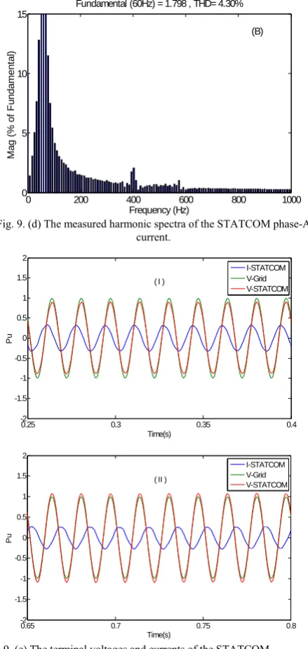
[image:5.595.65.264.55.205.2] [image:5.595.316.538.57.358.2] [image:5.595.63.279.252.366.2] [image:5.595.63.272.404.551.2] [image:5.595.318.533.577.732.2] [image:5.595.62.272.591.731.2]0 200 400 600 800 1000 0
5 10 15
Fundamental (60Hz) = 1.798 , THD= 4.30%
M
a
g (
%
of
F
u
ndam
ent
al
)
Frequency (Hz)
(B)
Fig. 9. (d) The measured harmonic spectra of the STATCOM phase-A current.
0.25 0.3 0.35 0.4
-2 -1.5 -1 -0.5 0 0.5 1 1.5 2
Time(s)
Pu
I-STATCOM V-Grid V-STATCOM ( I )
0.65 0.7 0.75 0.8
-2 -1.5 -1 -0.5 0 0.5 1 1.5 2
Time(s)
Pu
I-STATCOM V-Grid V-STATCOM ( II )
Fig. 9. (e) The terminal voltages and currents of the STATCOM. (I) Inductive operation and (II) Capacitive operation.
V. CONCLUSION
This paper has presented a new control method based on SVM switching strategy for the proposed hardware simplified 2L-4S STATCOM. The main feature of the proposed circuit and switching strategy is that it can fast modify the switching patterns of the internal power electronic switches of the proposed STATCOM to achieve the desired voltage with only 2 thirds of the number of power devices required in the conventional design. The paper has also developed a detailed dynamic model of the proposed 2L-4S STATCOM. The model has been verified with a practical design case in which the basic P-Q power flow control functions in a STATCOM are tested. Feasibility and overall performance of the new STATCOM system, including the simplified power circuitry and control subsystems have been verified via comprehensive digital time-domain simulations.
REFERENCES
[1] X. gping and S. Bhattacharya, “Performance improved during
system fault of angle controlled STATCOM by current control,”
IEEE Power and Energy Society General Meeting, pp. 1 – 8, 20-24 July 2008.
[2] K. Li, J. Liu , Z. Wang and B. Wei, “Strategies and Operating Point
Optimization of STATCOM Control for Voltage Unbalance
Mitigation in Three-Phase Three-Wire Systems,” IEEE Trans. PD,
Vol. 22, Issue 1, pp. 413 – 422, Jan. 2007.
[3] X. Zhengping and S. Bhattacharya, “STATCOM Control and
Operation with Series Connected Transformer Based 48-pulse
VSC,” IEEE Industrial Electronics Conference, pp. 1714 – 1719,
Nov. 2007.
[4] S. Qiang, L. Wenhua, Y. Zhichang, “Multilevel Optimal Modulation and Dynamic Control Strategies for STATCOMs
Using Cascaded Multilevel Inverters,” IEEE Transactions on
Power Delivery, vol 22, no 3, pp.1937 – 1946, July 2007.
[5] H. Xie, L. Angquist, H.-P. Nee, “Comparison of Voltage and Flux
Modulation Schemes of StatCom Regarding Transformer
Saturation During Fault Recovery,” IEEE Transactions on Power
Systems, vol 23, no 4, pp.1653 – 1661, Nov. 2008.
[6] R. Sternberger, D. Jovcic, “Theoretical Framework for Minimizing
Converter Losses and Harmonics in a Multilevel STATCOM,”
IEEE Transactions on Power Delivery, vol 23, no 4, pp.2376 – 2384, Oct. 2008.
[7] G. Zhao, J. Liu and Z. Wang, “An analysis on the influence of
interface inductor to STATCOM system with phase-shift control
and corresponding design considerations,” IEEE Conference on
Power Electronics and Motion Control, pp.2339 – 2344, May 2009.
[8] S. Mohagheghi, G.K. Venayagamoorthy, S. Rajagopalan, R.G.
Harley, “Hardware Implementation of a Mamdani Fuzzy Logic Controller for a Static Compensator in a Multimachine Power
System,” IEEE Transactions on Industry Applications, vol 45, no
4, pp.1535 – 1544, July-aug. 2009.
[9] N. oraphonpiput and S. Chatratana, “STATCOM Analysis and
Controller Design for Power System Voltage Regulation,”
IEEE/PES 2005 Transmission and Distribution Conference and Exhibition, pp. 1 – 6, July 2005.
[10] V. Spitsa, A. Alexandrovitz, E. Zeheb, “Design of a Robust State
Feedback Controller for a STATCOM Using a Zero Set Concept,”
IEEE Transactions on Power Delivery, vol 25, no 1, pp.456 – 467, Jan. 2010.
[11] B. Singh, S.S. Murthy, S. Gupta, “STATCOM-Based Voltage
Regulator for Self-Excited Induction Generator Feeding Nonlinear
Loads,” IEEE Transactions on Industrial Electronics, vol 53, no
5, pp.1437 – 1452, Oct. 2006.
[12] B. Singh, S.S. Murthy, S. Gupta, “Analysis and design of
STATCOM-based voltage regulator for self-excited induction generators,” IEEE Transaction on Energy Conversion, vol 19, no 4, pp.783 – 790, Dec. 2004.
[13] Q. Wei, R.G. Harley, G.K. Venayagamoorthy, “Coordinated
Reactive Power Control of a Large Wind Farm and a STATCOM
Using Heuristic Dynamic Programming,” IEEE Transactions on
Energy Conversion, vol 24, no 2, pp.493 – 503, June 2009.
[14] H. Xie, L. Angquist, H.-P. Nee, “Design and Analysis of a
Controller for a Converter Interface Interconnecting an Energy
Storage With the Dc Link of a VSC,” IEEE Transactions on Power
Systems, accepted for future publication, pp.1 – 9, 2009.
[15] H. Gaztanaga, I. Etxeberria-Otadui, D. Ocnasu, S. Bacha,
“Real-Time Analysis of the Transient Response Improvement of Fixed-Speed Wind Farms by Using a Reduced-Scale STATCOM
Prototype,” IEEE Transactions on Power Systems, vol 22, no
2, pp.658 – 666, May 2007.
[16] C.-H. Liu, Y.-Y. Hsu, “Design of a Self-Tuning PI Controller for a
STATCOM Using Particle Swarm Optimization,” IEEE
Transactions on Industrial Electronics, accepted for future publication, pp. 1 – 1, 2009.
[17] S. Rahimzadeh, M. Tavakoli Bina, A. Houshmand Viki, “Steady
State Model of STATCOM and SSSC Using Averaging
Technique,” IREE, Part-B, vol. 4. n. 6, pp. 1391-1403, 2009.
[18] G. Shahgholian, “Development of State Space Model and Control
of the STATCOM for Improvement of Damping in a
Single-Machine Infinite-Bus,” IREE, Part-B, vol. 4. n. 6, pp.
[image:6.595.59.279.64.527.2] [image:6.595.280.546.66.761.2]