Development and Analysis of Cold Rolled Sheet
Rolling Machine
Prof. Gaurav Gohane1, Karthik Devasani2, Rameshwar Shende3, Kartik Kamble4, Anup Kathane5, Rahul Timande6 1
Assistant Professor, 2, 3, 4, 5, 6UG Scholar, Department of Mechanical Engineering ,JDCOEM Nagpur-441501
Abstract: The sheet rolling machine is simple in operate, the skilled operator is not required to operate the machine. It consist of three roller one is upper roller which is adjustable and free to move up or down and other two is the lower roller which is fixed and it used to transfer the motion from electric motor to the metal sheet to obtained bending moment. The metal sheet is continuously feed in between upper roller and lower roller. The upper roller is acting load on metal sheet normally downward and also lower roller lifting force normally upward. This forces are deflecting the metal sheet from its original position and formed curvature, this curvature are used to forming shell. This paper deals with the study of metal sheet rolling machine, In which flat metal sheet are formed into hollow cylinder.
Keywords: Sheet rolling machine, Design and Analysis, Load, Bending moment, Deflection, Bending stress, Forces, Roller, Sheet.
I. INTRODUCTION
In this machine the process in which flat metal sheet of appropriate length are to be bend into the desire curvature or complete hollow cylinder. The sheet rolling is a simple process by using roller which is power operated by motor. In this machine there are three roller; first is upper roller which is flexible to move and other two are fixed and also use to provide motion to the metal sheet. The machine is simple in construction and working. Power is transfer from motor to roller using gearbox. Metal sheet rolling process is the continuous bending operation in which a strip of metal sheet is passed through between a roller, until the desire curvature doesn't obtained.
[image:1.612.176.438.481.618.2]The paper also contain how hollow cylinder formed there design and analysis procedure. The sheet rolling process is play important role in manufacturing industry, and there for it’s a large growing industrial area. This sheet metal are used to forming a hollow cylinder which is used in many industries such as Power Plants, Automobile sector and many more. Sheet fabrication ranges from Stamping, forming, drawing, High-Energy-Rate-Forming (HERF) to obtained desire shape. Fascinating shape may be bend from a single plane sheet of material without tearing or cutting, stretching, if incorporates one curved bend into the design. The sheet rolling is the process of bending continually of sheet metal piece along a linear axis.
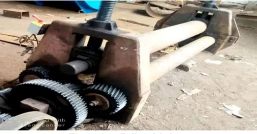
Fig. 1. Sheet Rolling Machine
The sheet rolling machine are included several component on it :-
1) Base : The base is the component of rolling machine in which all the other component are mount on the base. The base is made up of cast iron and it formed by standard channel of 70*940 (h*w).
2) Handle: The Handle is carries the upper roller such that it can moved down and up normal so that metal sheet feed between upper roller and lower roller.
4) Motor: The motor is mount on the base which required to transmit the power to the rollers for the providing the bending moment to the metal sheet. The HP of the motor may be change with respect to machine requirement.
Fig. 2. Motor
5) Rollers: The sheet rolling machine which two types of roller upper roller and lower roller. lower roller are fixed and it used to transfer the motion to the metal sheet, upper roller is movable along the y-axis of the machine it use to adjustment of metal sheet as will as to apply load on the metal sheet.
Fig. 3. Rollers
The entire process of metal sheet rolling is divided into three step:
1) Positioning of Blank Sheet or Plate: In this process the metal sheet adjust into lower roller for the pre bending operation.
2) Lowering the Upper Roller: This process are required for the fixed the metal sheet in between upper roller and lower roller
3) Feeding Metal Sheet: In this process the metal sheet are feed between the upper roller and lower roller this causes upward force acting on upper roller and the load is acting on the metal sheet because of self weight oh upper roller.
Fig.4 Block Diagram of sheet rolling machine
II. LITRETURE REVIEW
1) Pramod Vishwakarma: In this paper he review several research paper and conclude that the new changes in design will reduce crushing stresses in handling of roller machine on which upper roller is mounted. In addition to changes the efficiency of the machine will increase and will have a less maintenance which directly impact on the maintenance cost. [1]
2) Segun R Bello: In this research paper he developed metal sheet rolling machine for small scale industries, the market survey of RS bello show that the price or cost of imported component of rolling machine is 3,80,000Rs. To 5,00,000 Rs While the locally fabricated shape cost is low. [2]
3) Mr. Nitin P. Padghan: This paper are contain actual experiment of force calculation and analysis of different material on metal sheet. On the basis of calculation and result he conclude that the load is directly proportional to modulus of elasticity. [3]
4) Alie Wube Dametew: This paper contain multi-purpose bending operations, design and analysis and also various sheet metal forming, the relationship of productivity and economic analysis. The objective of this paper is to improve the production of metal sheet rolling machine. [4]
[image:2.612.186.428.257.331.2]6) Obaje Onuche: In this paper he developed motorized metal sheet rolling machine, The aim of research is to design rolling machine to saving the cost and time. The method used to calculation is analytical method, after designing the machine he conclude that power operated metal sheet rolling machine is more efficient and it involve less time for the sheet rolling. [6]
III. IDENTIFICATION OF GAP IN THE LITERATURE
In the normal practice roller bending still heavily depend upon skill operator, manpower and time. So the aim of the project is to analyses and development of power operated sheet rolling machine in the basis of design calculation.
IV. METHODOLOGY
A. To study design and analysis of sheet metal rolling machine.
B. Designing for the various measurement of the sheet rolling machine.
C. Suggest the new changes in design.
D. Fabrication of change in design in low cost.
V. STANDARD DESIGN PROCEDURE
A. Design Considerations
Consider two lower roller with center distance ‘α’ (mm) and diameter ‘d’ on which the flat metal sheet are rest on it. Upper roller acting force on the plate to bend the metal sheet with various parameter such as sheet width, sheet thickness, sheet material properties, shell diameter to rolled sheet.
Fig.5.1. Free Body diagram of Forces acting on Sheet
The calculation load, stresses and forces acting on the metal sheet-
EI
WL
48
3
Where,
δ= deflection of metal sheet
=13mm
W=Initial load acting on metal sheet L=length of sheet between two rollers
=450mm
E=Modulus of elasticity(mild steel)
=210*103
1) Initial Load Acting On Sheet KN W W h b W L I E W 69 . 239 450 ) 12 20 * 250 ( * 10 * 210 * 48 * 13 450 ) 12 * ( * 10 * 210 * 48 * 13 * * 48 * 3 3 3 3 3 3 3
Bending stress acting on sheet
Nmm M M d W M I MY 6 3 10 * 92 . 53 2 450 * 10 * 67 . 239 *
Y=Perpendicular distance from center of rolling sheet to the neutral axis.
Y=340mm 3 2 3 6
10
*
110
10
*
67
.
166
340
*
10
*
92
.
53
mm
N
2) Forces Acting On Metal Sheet
Cos
F
F
Sin
d
M
F
2 1 min 22
*
2
Where,F2, F1 are the forces acting on sheet
dmin - final diameter of sheet to be rolled.
θ = angle between defiled line
d2 = diameter of lower roller
N F
Sin F
Sin d
M F
3 2
6
2 min 2
10 * 17 . 274
) 34 . 35 ( * 680
10 * 92 . 53 * 2
* 2
F N
Cos F
Cos F F
3 1
3 1
2 1
10 * 29 . 447
) 43 . 35 ( * 10 * 17 . 274 * 2 2
VI. CONCLUSION
The changes in design will reduce the maintenance cost and crushing stresses in handle of sheet rolling machine. It save manpower, operation time and improve the efficiency of the machine. In compare with manual operated machine the power operated machine is more efficient.
REFERENCES
[1] Pramod vishwakarma “Design and analysis of M.S Roller in sheet metal rolling machine” IJERGS Vol.4, Issue 2, March-April 2016. [2] R. S. Bello “Development and evaluation of metal rolling machine for small-scale manufacturers” Vol. 15, No.3
[3] Mr. Nitin P. Padghan, ,“Force Analysis of Metal Sheet in Bending Operation on Sheet Bending Machine” IJERTV4IS010115,Vol.4 Issu01, Jan-2015 [4] Alie Wube Dametew,,“Design and Analysis of Multipurpose Machine for the Productivity of Sheet rolling machine”Volume 17 Issue 5 Version 1.0 Year 2017 [5] Aniruddha Kulkarni Mangesh Pawa “Sheet Metal Bending Machine ” VOLUME 2, ISSUE 3, March.-2015
[6] Obaje Onuche,“Development of a Motorized Sheet rolling Machine” AIR32027,NLM Id:10666096,Oct.-2018
[7] P. S. Thakare1 , P. G. Mehar ,“Productivity Analysis of manually operated and power operated sheet bending machine” IJERA Vol.2 Issue 2,April-2012, pp.111-114
[8] Yiljep, T. P. 1999. Characterization of major Agricultural Tools manufacturing Artisans in Northern Nigeria. Journal of agric. Eng. & Tech. 7: 45-52. [9] K. L. Elkins, R. H. Sturges, “ Spring back analysis in Air bending”, Tran, ASME, J. Manufacturing science and engineering, 121, Nov. 1999, PP. 679-688 [10] Himanshu V. Gajjar, Anish H. Gandhi, Tanvir A Jafri, and Harit K. Raval” Bendability Analysis for Bending of C-Mn Steel Plates on Heavy Duty 3-Roller
Bending Machine”
[11] Jong Gye Shin, Tac Joon Park & Hyunjune Yim ― Roll Bendingǁ, Tran, ASME, J. Mechanical Design, 123 May 2001, PP 284-290 [12] M.B. Bassett, and W. Johnson ― Design of machine elementsǁ, Tata mc-Graw Hill Publication
[13] Y. H. Lin, M. Hua, “Mechanical analysis of edge bending mode for four-roll plate bending process”, Computational Mechanics, Springer-Verlag 1999, pp 396-407
[14] George, L. 1983. The theory and practice of metal work. 3rd edition. PTF low price edition. Longman, London