Influence of steel reinforcement corrosion on the stiffness
of simply supported concrete beams
O'FLAHERTY, Fin <http://orcid.org/0000-0003-3121-0492>, MANGAT, Pal <http://orcid.org/0000-0003-1736-8891>, LAMBERT, Paul
<http://orcid.org/0000-0002-2815-1674> and BROWN, E. H.
Available from Sheffield Hallam University Research Archive (SHURA) at:
http://shura.shu.ac.uk/3975/
This document is the author deposited version. You are advised to consult the publisher's version if you wish to cite from it.
Published version
O'FLAHERTY, Fin, MANGAT, Pal, LAMBERT, Paul and BROWN, E. H. (2010). Influence of steel reinforcement corrosion on the stiffness of simply supported concrete beams. In: SAUSE, Richard and FRANGOPOL, Dan, (eds.) Bridge maintenance, safety and management - IABMAS'10. Bridge, maintenance, safety and management . CRC press.
Copyright and re-use policy
See http://shura.shu.ac.uk/information.html
1 INTRODUCTION
The increasing age of the highway bridge stock throughout Europe has led to increased deterioration in existing structures. Surveys have indicated that the main reasons for deterioration, besides normal wear and tear, are the increasing weights and volume of traffic using the road network, and adverse envi-ronment conditions such as exposure to chlorides and freeze-thaw attack. The magnitude of the capital investment in European bridge stock requires that ef-fective maintenance is provided to ensure that the bridges are kept in safe service at optimum cost. Re-liable assessment methods are urgently required to assist the bridge engineer to evaluate the residual ca-pacity of deteriorated elements.
When steel reinforcement corrodes, tensile stresses are generated in the concrete as a result of the expansive corrosion products. Since concrete can endure much less tensile stress than compressive stress, tensile cracks are readily nucleated and prop-agated as a result. The development of corrosion products along the bar surface may affect the failure mode and ultimate strength of flexural members due to two causes: firstly, due to a reduction in the de-gree of bar confinement caused by an opening of longitudinal cracks along the reinforcement and, se-condly, due to significant changes at the steel-concrete interface caused by changes in the surface conditions of the reinforcing steel (Al-Sulaimani et al. 1990). In all corrosion cases, repair is necessary to increase the service life of the member (Mangat &
O'Flaherty 1999, 2000) and it is estimated to cost approximately €1.5bn in Europe each year (Davies 1996).
2 BACKGROUND
In this investigation, the steel in reinforced concrete beams was subjected to an accelerated corrosion technique in the laboratory using one of the several methods available. The galvanostatic method was used in this study to simulate the field conditions. The method involves passing a direct current through the reinforcement to accelerate corrosion. The galvanostatic corrosion is carried out whilst the beam is unloaded, which is different from the corro-sion in actual structures. The corrocorro-sion by galvanos-tatic method is general, whereas actual structures have some specific areas that are more prone to cor-rosion. Thus, in the latter case, there is always the possibility of pitting corrosion whereby the cross-sectional area of the reinforcing bars could be signif-icantly reduced, thus reducing the tensile strength of the reinforcing bars. However, in reality, localised pitting corrosion extends to many sites resulting in extensive and relatively uniform levels of corrosion covering large areas of reinforcement (Mangat & El-garf 1999). In these tests, the aim was to subject the steel reinforcement to general corrosion.
Concrete structures which have suffered from corrosion to the steel require maintenance to increase their service life. However, it is difficult to make a
Influence of steel reinforcement corrosion on the stiffness of simply
supported concrete beams
F. J. O'Flaherty, P. S. Mangat & P. Lambert
Centre for Infrastructure Management, Sheffield Hallam University, Sheffield, S1 1WB, UK
E. H. Browne
Halcrow Group Limited, Birmingham, B16 8PE, UK
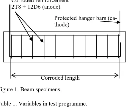
Protected hanger bars (ca-thode)
decision as to when repair is required without know-ing how much the capacity has been reduced due to deterioration. Shear reinforcement normally corrodes first as it is nearer to the concrete surface but main steel, too, can be affected simultaneously if the cor-rosion inducing elements penetrate deep into the concrete. One of the objectives of the laboratory work was to evaluate the influence of corrosion to the main and shear reinforcement on the stiffness of simply supported beams.
3 EXPERIMENTAL PROCEDURE
[image:3.595.37.259.447.627.2]A total of twenty reinforced concrete beams were tested to examine the influence of reinforcement cor-rosion on the stiffness. Details of test specimens are given in Figure 1 and Table 1. Beams were 910 mm long with a cross-section of 100 mm x 150 mm deep. Span was 750 mm. All specimens were de-tailed for flexural failure; sufficient links were pro-vided to ensure adequate shear capacity at the antic-ipated maximum load of the corroded beam. Beams are identified as follows (Table 1): e.g. 2T8/5+12D6/10 gives the number, type, and diame-ter of the main steel in mm/target percentage of cor-rosion + number, type, and diameter of the links in mm/target corrosion. 2T8/0+12D6/0 were tested without corrosion to serve as control specimens (Ta-ble 1). Cover throughout was 50 mm to the shear reinforcement and 56 mm to the main steel.
Figure 1. Beam specimens.
Table 1. Variables in test programme. Beam ID
(main steel /shear steel)
Target Corrosion (main and shear)
No. of specimens
(%)
2T8+12D6
0 2
5 6
10 6
15 6
Main reinforcement consisted of high yield (ribbed) bars with a nominal characteristic strength of 460 N/mm2. Shear reinforcement was 6 mm di-ameter plain round mild steel bars with a nominal yield strength of 250 N/mm2. Shear reinforcement
was spaced at 65 mm centres for 56 mm cover to main steel reinforcement. Hanger top bars for all beams consisted of two 6 mm diameter plain round mild steel bars with a yield strength of 250 N/mm2. The steel reinforcement was weighed before casting to enable the actual percentage corrosion to be calcu-lated at a later stage. Corrosion of the top reinforce-ment (hanger bars) was prevented by providing shrink wrap tubing at the points of contact with the shear steel reinforcement to break the electrical cir-cuit and hence prevent current flow during the acce-lerated corrosion process. Corrosion of the main and shear reinforcement was conducted simultaneously using a multi channel power supply. Shrink wrap tubing was again provided at the points of contact between the shear and main steel to enable each bar to be corroded separately using the multi channel power supply.
Test specimens were cast in the laboratory using a concrete with target cube strength of 40 N/mm2. Mix proportions were 1:1.7:3.8 of Portland cement: fine aggregate: coarse aggregate. Fine and coarse aggre-gates were oven dried at 100C for 24 hours. Cal-cium chloride (CaCl2) was added to the mix (1% by
weight of cement) in order to promote corrosion of the reinforcement. The material was placed in steel moulds in three layers, each layer being carefully compacted on a vibrating table. The specimens were then placed in the mist curing room (20C and 95% ± 5% Relative Humidity) for 24 hours. The samples were demoulded after 1 day and cured in water at 20C for a further 27 days (28 days in total). Speci-mens were then transferred to a tank filled with a sa-line solution for accelerated corrosion at 28 days age. A 3.5% CaCl2 solution was used as the
electro-lyte. The direction of the current was arranged so that the main and shear reinforcing steel served as the anode and the hanger bars and additional copper, which was added to the tank, acted as the cathode.
A constant current density of 1 mA/cm2 was passed through the main and shear reinforcement. This current density was adopted on the basis of pi-lot tests to provide desired levels of corrosion in a reasonable time. The current supplied to each speci-men was checked on a regular basis and any drift was corrected.
The control specimens (zero percent corrosion) were tested at the age of 28 days but the deteriorated beams were tested at 42, 56 and 63 days for the 5, 10 and 15% target corrosion respectively due to the time taken to reach the desired levels of corrosion. All specimens were tested under four point bending to determine the ultimate flexural strength. Prema-ture shear failure was prevented by sufficient shear reinforcement. The testing machine loading rate was set at 5 kN/min.
The rebars were retrieved from the concrete after the testing program and reweighed to establish the precise level of corrosion.
4 RESULTS AND DISCUSSION
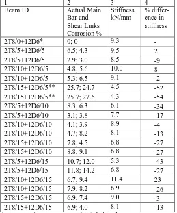
The load-deflection curves for the beams under in-vestigation are given in Figure 2 and include 18 cor-roded beams and the average of two control beams. The effect of the degree of corrosion on the overall stiffness of corroded flexural member is tabulated in Table 2 and is taken from the data presented in Fig-ure 2. Referring to Table 2, beams are identified in column 1. The actual percentage of reinforcement corrosion, measured as described in Section 3, is given in column 2. Column 3, Table 2, shows the stiffness of the beams after testing in the laboratory. The stiffness was determined via the straight line portion of the graph from the origin in Figure 2. The percentage difference in loss of stiffness between the control beam (2T8/0+12D6) and the corroded beams is given in column 4.
[image:4.595.32.291.473.784.2]To gain a better understanding of the performance of the beams when both main and shear reinforce-ment are subjected to corrosion, Figure 3 shows the effect of corrosion on the stiffness. Referring to Fig-ure 3, the beam stiffness, obtained from the slope of the load-deflection curves in Figure 2, is plotted against the degree of main reinforcement corrosion only, as this is considered the main parameter with respect to loss of stiffness (the shear reinforcement was also corroded in the test as this better represents actual conditions). Generally, an increase in corro-sion leads to a decrease in stiffness. At very high le-vels of corrosion (>25%), the mode of failure changes from flexure to shear.
Table 2. Experimental data.
1 2 3 4
Beam ID Actual Main Bar and Shear Links Corrosion % Stiffness kN/mm % differ-ence in stiffness
2T8/0+12D6* 0; 0 9.3 -
2T8/5+12D6/5 6.5; 4.3 9.5 2 2T8/5+12D6/5 2.9; 3.0 8.5 -9 2T8/10+12D6/5 4.8; 5.6 10.0 8 2T8/10+12D6/5 5.3; 6.5 9.1 -2 2T8/15+12D6/5** 25.7; 24.7 4.5 -52 2T8/15+12D6/5** 25.7; 27.6 4.3 -54 2T8/5+12D6/10 8.3; 6.3 6.1 -34 2T8/5+12D6/10 3.1; 3.8 7.7 -17 2T8/10+12D6/10 4.1; 3.9 8.9 -4 2T8/10+12D6/10 4.7; 8.2 8.1 -13 2T8/15+12D6/10 7.8; 4.5 6.8 -27 2T8/15+12D6/10 8.8; 9.1 6.8 -27 2T8/5+12D6/15 10.7; 12.0 5.3 -43 2T8/5+12D6/15 11.8; 14.2 6.8 -27 2T8/10+12D6/15 6.7; 9.4 11.4 23 2T8/10+12D6/15 7.9; 8.2 6.9 -26 2T8/15+12D6/15 6.9; 7.4 9.0 -3 2T8/15+12D6/15 6.9; 4.0 8.1 -13 * average of two specimens ** failed in shear
4.1 Influence of corrosion on stiffness
Referring to Table 2, col. 4, the percentage differ-ence in stiffness between the control beam (2T8/0+12D6) and the corroded beams is given. This data is plotted against the degree of corrosion of the main steel in Figure 4 but excludes three positive da-ta point from column 4 which are considered to be erroneous - 2T8/5+12D6/5, 2T8/10+12D6/5 and 2T8/10+12D6/15 and the two beams which failed in shear (2T8/15+12D6/5, 2T8/15+12D6/5). Referring to Figure 4, a linear correlation is evident with R2=0.58. The decrease in stiffness is equal to 2.83 times the degree of corrosion of the main steel.
The failure load of the control beam was 41.4 kN (Figure 2). However, if the service load is estimated as 40% of the ultimate (control) load to account for factors of safety included in the design (dead load: 1.4; live load: 1.6; materials: 1.5 for concrete and 1.05 for steel), the service load would be approx-imately 16.6kN. Therefore, the deflection of this beam in service, assuming a stiffness of 9.3 kN/mm (Table 2) and a service load of 16.6 kN would be 1.8 mm (deflection = 16.6 kN / 9.3 kN/mm). However, the allowable deflection is span/250 (British Stan-dards Institution), or 3mm for these beams meaning only a further 1.2mm of deflection is required before the beam is outside of allowable deflection limits. To estimate the percentage of corrosion required to cause this increase in deflection, the service load is assumed to remain at 16.6 kN but the deflection is assumed to reach its maximum allowable limit of 3mm. Therefore, since stiffness = service load / def-lection, stiffness = 16.6 kN / 3mm or 5.53 kN/mm.
This means that the stiffness of the beam would have to decrease to 5.53 kN/mm before it exceeds serviceability limits, a decrease of 40% ((9.3 - 5.53)/9.3). Applying this percentage loss of stiffness to Figure 3, main steel corrosion would have to ex-ceed 14% before deflection criteria becomes an issue (40%/2.83).
5 CONCLUSIONS
The main conclusions from the results reported in this paper are as follows and apply within the limit of the parameters covered by the test data in the pa-per.
reinforced concrete beams show a loss in stiffness with increasing corrosion of the main and shear steel reinforcement;
an equation linking the decrease in stiffness to main steel corrosion was determined as follows:
main steel corrosion would have to exceed 14% before deflection criteria are exceeded.
6 ACKNOWLEDGEMENTS
The work described in this paper forms a part of a research project entitled 'Residual strength of cor-roded reinforced concrete beams' which was carried out at Sheffield Hallam University. The assistance received from the technical staff in the laboratory is gratefully acknowledged. The authors also acknowl-edge with thanks the support of Halcrow Group Li-mited and CPI Aps in providing the multi-channel power supply for inducing accelerated corrosion.
7 REFERENCES
Al-Sulaimani, G. et al. 1990. Influence of Corrosion and Crack-ing on the Bond Behavior and Strength of Reinforced Con-crete Members. ACI Structural Journal 87 (2): 220-231. British Standard Institution 1997. Structural use of concrete:
Code of practice for, design and construction BS 8110-1. Davies, H. 1996. Repair and maintenance of corrosion
dam-aged concrete: Materials strategies, Concrete Repair, Reha-bilitation and Protection. London: E &FN Spon.
Mangat, P.S., Elgarf, M.S. 1999. Flexural strength of concrete beams with corroding reinforcement, ACI Structural Jour-nal 96 (1): 149-158 Jan-Feb 1999
Mangat, P.S., O’Flaherty, F.J. 1999. Long-term performance of high stiffness repairs in highway structures, Magazine of Concrete Research 51 (5): 325-339.