Recommendations for measuring tennis racket parameters
ALLEN, Tom, GRANT, Robyn, SULLIVAN, Matthew, TARABORRELLI, Luca,
CHOPPIN, Simon <http://orcid.org/0000-0003-2111-7710>, SPURR, James
and HAAKE, Steve <http://orcid.org/0000-0002-4449-6680>
Available from Sheffield Hallam University Research Archive (SHURA) at:
http://shura.shu.ac.uk/18863/
This document is the author deposited version. You are advised to consult the
publisher's version if you wish to cite from it.
Published version
ALLEN, Tom, GRANT, Robyn, SULLIVAN, Matthew, TARABORRELLI, Luca,
CHOPPIN, Simon, SPURR, James and HAAKE, Steve (2018). Recommendations
for measuring tennis racket parameters. Proceedings, 2 (6), p. 263.
Copyright and re-use policy
See
http://shura.shu.ac.uk/information.html
Sheffield Hallam University Research Archive
Proceedings2018, 2, 263; doi:10.3390/proceedings2060263 www.mdpi.com/journal/proceedings
Proceedings
Recommendations for Measuring Tennis
Racket Parameters
†Tom Allen 1,*, Robyn Grant 2, Matthew Sullivan 2, Luca Taraborrelli 1, Simon Choppin 3,
James Spurr 4 and Steve Haake 3
1 Sports Engineering Research TEAM, Manchester Metropolitan University, Manchester M1 5GD, UK;
2 Conservation, Evolution and Behaviour Research Group, Manchester Metropolitan University,
Manchester M1 5GD, UK; [email protected] (R.G.); [email protected] (M.S.)
3 Centre for Sports Engineering Research, Sheffield Hallam University, Sheffield S10 2LW, UK;
[email protected] (S.C.); [email protected] (S.H.)
4 International Tennis Federation, London SW15 5XZ, UK; [email protected]
* Correspondence: [email protected]; Tel.: +44-161-247-6265
† Presented at the 12th Conference of the International Sports Engineering Association, Brisbane, Queensland, Australia, 26–28 March 2018.
Published: 13 February 2018
Abstract: Tennis rackets have advanced significantly since the invention of the game in 1874, including innovations in both shape and materials. Advances in these design parameters have implications for racket performance, especially swing speed. This study tested one hundred rackets, spanning brands and eras, using simple, portable instruments in order to pilot protocols and make recommendations for streamlining testing procedures for tennis rackets. A wide range of properties were measured and documented for each racket. We suggest that since Transverse and Lateral Moment of Inertia are well correlated, measuring both is not necessary when processing a large number of rackets. In addition, it is also possible to predict the Transverse Moment of Inertia well from models that use simple dimension and mass measurements, which may be preferable in larger studies. Exploring the use of more complex modelling will allow us to better understand the impact of tennis racket design on performance in the future.
Keywords: sports equipment testing; modelling; moment of inertia; equipment performance; racket design
1. Introduction
Proceedings 2018, 2, 263 2 of 6 Engineers, designers and biomechanists undertake research to further our understanding of racket performance [7], with attention paid to issues such as the factors affecting frame vibrations [8] and swing speed [5,6]. Haake et al. [2] represents the most comprehensive work on how rackets have developed to date, having characterised 150 from the 1870s to 2007, including measurements of overall length, head length/width, grip length, mass, centre of mass (COM), “swing-weight”, “twist-weight” and vibration frequency. This paper lays the foundations for future research, by piloting protocols on one hundred rackets, and making recommendations for succinctly characterising a much larger number in the future, while also measuring more properties.
2. Materials and Methods
Ninety-one rackets were characterised at a brand’s headquarters. There were over one thousand rackets in their collection, spanning a range of brands and eras. Rackets were selected from different brands and eras (e.g., Dunlop Maxply Fort, Prince Pro, Yonex R22, Wilson Pro Staff, HEAD Radical, Babolat Pure Drive), including those which were distinctive (e.g., Gamma Big Bubba—Xtra
long 32″, Kuebler Original Widebody 280 Hz, Snauwaert graphite ergonom) to thoroughly assess the
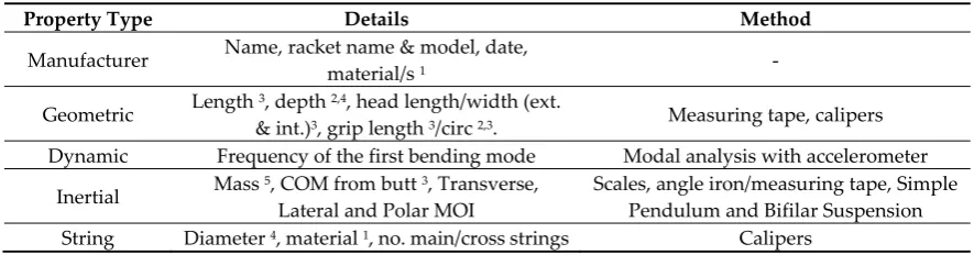
[image:3.595.76.519.351.467.2]robustness of the protocols. Nine rackets came from the University. Only strung rackets were selected. For each racket, manufacturer details and key measurements were recorded (Table 1), a photograph was taken, and any distinguishing features were photographed and documented.
Table 1. Properties documented and measured for each racket.
Property Type Details Method
Manufacturer Name, racket name & model, date,
material/s 1 -
Geometric Length
3, depth 2,4, head length/width (ext.
& int.)3, grip length 3/circ 2,3. Measuring tape, calipers
Dynamic Frequency of the first bending mode Modal analysis with accelerometer Inertial Mass
5, COM from butt 3, Transverse,
Lateral and Polar MOI
Scales, angle iron/measuring tape, Simple Pendulum and Bifilar Suspension String Diameter 4, material 1, no. main/cross strings Calipers
1 As available, 2 Max./min., mean reported, resolution of: 3 1 mm using measuring tape; 4 0.1 mm
using calipers; and 5 1 g using scales
Modal analysis was used to determine the frequency of the first bending mode. The racket was suspended with string and a sensor (MetaWear CPro, Mbientlab Inc., San Francisco, CA, USA) was strapped to the handle (8 g sensor & strap). The string bed was ‘tapped’ with a ball to excite vibrations, with the accelerometer sampling at 800 Hz (BMI160 inertial measurement unit, Bosch Sensortec, Reutlingen, Germany). Data was logged in the sensor memory, transferred to an iPad via Bluetooth and downloaded (MetaWear App) to a laptop. The Fast Fourier Transform (FFT) function in Matlab R2106a (Mathworks) was applied to obtain the frequency. Tests were undertaken twice and the mean reported. The maximum difference between trials for a racket was 2 Hz (5 occurrences). Accuracy was assessed by fixing the sensor to a shaker and exciting frequencies of 100, 150 and 190 Hz, typical for tennis rackets [2] and predictions fell within 2 Hz.
occurrences) MOIs, equating to ~1.5% difference, and 2 s for Polar MOI (one occurrence), equating to ~5% difference.
Accuracy was assessed using two rods of known theoretical MOIs close to typical values for
rackets. The Polar MOI of one rod was 0.00186 kg·m2, and the Transverse MOI about the end of the
other was 0.0576 kg·m2. Three operators ran each test twice, resulting in a total of six for each MOI.
Polar MOI was measured as 0.00190 kg·m2 and Transverse MOI ranged from 0.0567 to 0.0577 kg·m2
(mean value 0.0570 kg·m2), indicating similar agreement to theoretical values and the accuracy
results reported by Spurr et al. [9] (mean within 2%). Attempts were made to measure MOI with the sensor, by attaching it to the rods and then applying an FFT to the signal (accelerometer & gyroscope) to predict the frequency of oscillation, but initial results indicated that this was less accurate and more time-consuming than using the stopwatch.
As well as measuring the Transverse MOI (IT) in our Pendulum technique, models were
[image:4.595.87.511.281.413.2]investigated to determine their suitability for predicting Transverse MOI from racket dimensions, mass and COM location [10,11]. The simplest approach is to model the racket as a beam [10] (Figure 1b).
Figure 1. Schematic showing (a) racket; (b) beam; (c) two-section beam [10]; (d) unequal two-section beam [11]; (e) five section beam [11]—two-dimensional and (f) five section beam [11]—one-dimensional. m = mass, l = length, w = width, b = distance to COM, h = handle and f = frame.
Cross [10] improved on the beam model, dividing the racket into two equal lengths, corresponding to the mass of the frame and handle (two-section beam; Figure 1c):
=( + 7 )
12 (1)
As the mass of the sections sum to the racket mass, their values can be obtained using:
=(4 )
3 4 (2)
Goodwill [11] divided the racket into two unequal lengths, corresponding to the mass and length of the fame and handle (unequal two-section beam; Figure 1d):
=
3 + ( 12 + ( +2) ) (3)
Similarly, the mass of the sections can be obtained using:
= 2 + ( + 2) (4)
Proceedings 2018, 2, 263 4 of 6
=
3 + 12 + ( + 2) + 6 + ( + + 2) + 12
+ ( + + +
2) + ( + +
3
2 + )
(5)
The five-section beam model starts with a two-dimensional approximation of a racket, with a rectangular head and two vertical throat sections (Figure 1e). The width of the rectangle was set to 75% of the racket width. Translation to a one-dimensional beam can be obtained once section masses
are known (Figure 1f). In this work, lf2 was assumed to equal lf4 (from int. & ext. head length), so mf2
equaled mf4. As the mass of all sections sum to the racket mass, their values can be obtained using:
= 2 + ( + 2 ) + + + + 2 + 2 ( + + + 2 ) (6)
A Stepwise Linear Regression model was also conducted to examine the racket parameters that best predict the Transverse MOI; it was conducted on all dimension variables (lengths, widths, depths), as well as COM location and mass.
3. Results
[image:5.595.138.480.79.128.2]Rackets were from twenty-seven manufacturers (36 HEAD, 8 Prince, 7 Wilson & Dunlop, 5 Babolat, 4 Kuebler & Volkl, 3 Yonex & Donnay, 2 Fischer, Neoxx, Rossignol, Slazenger & Techno, 1 Snauwaert, Wavex, Gamma, Huntak, Kneissel, Adidas, Montana, Prokennex, Alibor, Spinspot, Pottak, ATP & Life Sport). The majority were made of fibre-reinforced composites (85), followed by wood (8), metal (3) or a combination of different materials (e.g., fibre-reinforced wood) (4). Table 2 summarises geometric properties and Table 3 summarises inertial properties, string bed properties and frequency of the first bending mode. Distinguishing features included holes in the frame (Prince Ozone 7), extended string bed/no throat section (Alibor TX 9980), asymmetric frames (Snauwaert graphite ergonom), adjustable string bed patterns (HEAD Extreme Rev Pro) and unusual throat sections (Rossignol F200 Wilander).
Table 2. Geometric properties in meters. Mean ± Standard Deviation, Range.
Length Head length Head width Frame depth Grip
External Internal External Internal Max. Min. Length Circumference Max. Min.
0.69 ± 0.02 0.35 ± 0.03 0.33 ± 0.03 0.26 ± 0.02 0.24 ± 0.02 0.02 ± 0.00 0.02 ± 0.01 0.19 ± 0.01 0.14 ± 0.00 0.11 ± 0.00
[image:5.595.76.520.490.542.2]0.66–0.81 0.30–0.49 0.27–0.46 0.22–0.31 0.20–0.29 0.01–0.04 0.01–0.03 0.15–0.24 0.12–0.15 0.10–0.13
Table 3. Inertial and string properties and vibration frequency. Mean ± Standard Deviation, Range
Mass (kg)
COM (m)
Transverse MOI (kg·m2)
Lateral MOI
(kg·m2) Polar MOI (kg·m
2) String
Diameter (mm) No. Main
No. Cross
Frequency (Hz)
0.32 ± 0.04 0.34 ± 0.02 0.051 ± 0.005 0.053 ± 0.005 0.00135 ± 0.00019 1.3 ± 0.1 16 ± 1 19 ± 1 144 ± 30
0.22–0.40 0.30–0.43 0.041–0.069 0.042–0.071 0.00091–0.00182 1.1–1.6 14–20 15–22 98–242
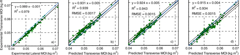
Figure 2a shows experimental Transverse versus Lateral MOI. It was not possible to measure Transverse MOI for two asymmetric rackets (Neoxx, ET 320 Pro and ST 285), so these were excluded.
The MOIs were well correlated as the correlation coefficient, R, was very close to 1. Lateral MOI was
slightly higher, as evidenced by an intercept of −0.001 kg m2. Figure 2b–d shows that Transverse
MOI was predicted well by all the models. All models were well correlated with the data (all R2 >
[image:5.595.81.517.572.612.2]sixty-five for the unequal-two section beam and only fifty-nine for the two-section beam. The Stepwise Linear Regression model indicated that mass (partial correlation (pC) = 0.941), COM location (pC = 0.864), racket length (pC = 0.492), and head width (pC = 0.245) all significantly
contributed to Transverse MOI (R2 = 0.936, p < 0.001), although removing head width did not have
[image:6.595.90.508.155.252.2]much of an effect on the model overall (R2 = 0.930, p < 0.001).
Figure 2. (a) Transverse versus Lateral MOI, experimental Transverse MOI versus; (b) two-section beam; (c) unequal two-section beam and (d) five-section beam.
4. Discussion
The properties of one hundred rackets, from twenty-seven manufacturers and different eras, were characterized using low-cost techniques; overall properties were close to previously reported values (e.g., [2,9–12]), although not all of these parameters (e.g., frame depth, no. of strings) have been well documented previously for so many rackets. The information presented here provides typical racket values and ranges, which could be useful for predicting performance using models.
Manufacturer details and materials data—were sometimes stated on a tag or text graphic (e.g., graphite) or estimated from visual inspection (e.g., wood, aluminum), but future work should consider the level of confidence in this information. In a similar manner, it was not feasible to identify string materials from visual inspection. Moreover, as strings can be replaced documenting their properties—material and diameter—is not recommended in future work. The same applies for measuring handle circumference, as grips vary, degrade and may not be original. The minimum value of frame depth often corresponded to the throat section. Future work could document the maximum and minimum depth of the frame and throat. Distinguishing features often fell into categories, such as asymmetric geometry, unusual head shapes, unusual throat sections or holes in the frame. Future work could document these features within categories, to save time and facilitate analysis, only including descriptions for particularly distinctive rackets.
Modal analysis with the wireless sensor was fairly time-consuming and future work could explore options to streamline the process, such as using a wired accelerometer. The range in vibration frequency was relatively small, with many rackets having similar values. Differences were, however, observed by the operator in how rackets damped frame vibrations. For some rackets, the lowest frequency did not correspond to the out of plane bending mode, rather it was the in plane bending mode (e.g., Kuebler Original Widebody 280 Hz, which had a max frame depth of 33 mm). Future work could document the frequency of both in plane and out of plane bending modes, as well as investigating damping coefficients.
Measurements of MOI were particularly time consuming, taking around ~30 to ~80 s for 50 oscillations. As Transverse and Lateral MOI were highly correlated [12], it may not be strictly necessary to measure both when characterizing a large number of rackets. It is also possible to predict Transverse MOI reasonably well using a two-section, unequal two-section or five-section beam model. The accuracy of the three models for predicting Transverse MOI was similar, so the unequal two-section beam model may be preferable, due to its relative simplicity. Furthermore, the regression analysis indicated that, while including head width had a significant impact on Transverse MOI, overall, results were not very different when it was removed. Mass, COM location, racket length and head width were the best predictors of Transverse MOI, in that order. Mass, length and width are easy to measure accurately, however the accuracy in the measurement of COM
0.04 0.05 0.06 0.07 0.04 0.05 0.06 0.07 E xper im ent al T ra ns ve rs e M O I ( kg m 2)
Experimental Lateral MOI (kg m2) y = 0.989 x - 0.001 R2 = 0.979
a)
0.04 0.05 0.06 0.07
y = 0.931 x + 0.005 R2 = 0.939 RMSE = 0.0017
Predicted Transverse MOI (kg m2) b)
0.04 0.05 0.06 0.07
y = 0.924 x + 0.005 R2 = 0.943 RMSE = 0.0015
Predicted Transverse MOI (kg m2) c)
0.04 0.05 0.06 0.07
y = 0.915 x + 0.004 R2 = 0.934
RMSE = 0.0015
Predicted Transverse MOI (kg m2)
Proceedings 2018, 2, 263 6 of 6 location could be improved by using load cells. Future work could streamline the testing process by using a model to predict MOI. As some rackets had asymmetric heads, which is typical in vintage specimens [2], further work should determine the suitably of the models for predicting Transverse MOI. Further work could also look to develop, or fine-tune, the models to increase accuracy of MOI predictions. More detailed modelling of key rackets, such as finite element analysis [13], might give a greater understanding of performance parameters.
5. Conclusions
One hundred tennis rackets were characterized using simple techniques. Transverse and Lateral MOI were well correlated, so measuring both is not deemed necessary when characterizing a large number of rackets. Transverse MOI was predicted reasonably well using models, and employing these could streamline the process of characterising rackets. Future work could employ load cells to measure COM location to ensure high accuracy when predicting Transverse MOI. Key rackets could then be selected for more detailed modelling using finite element analysis.
Acknowledgments: The authors would like to thank HEAD Sports for providing access to their racket collection. The authors would like to thank “Fondazione Ing. Gini” for providing funding for this work.
Conflicts of Interest: The authors declare no conflict of interest
References
1. Wingfield, W. The Game of Sphairistikè or Lawn Tennis, Facsimile of 1874 edition; Artist’s and Photographers’ Press Ltd.: Wisley, UK, 2008.
2. Haake, S.J.; Allen, T.B.; Choppin, S.B.; Goodwill, S.R. The evolution of the tennis racket and its effect on serve speed. In Tennis Science and Technology; Miller, S., Capel-Davies, J., Eds.; International Tennis Federation: London, UK, 2007; Volume 3, pp. 257–271.
3. Head, H. Tennis Racket; U.S. Patent 3,999,756; US Patent and Trademark Office: Washington, DC, USA, 1976.
4. Kuebler, S. Book of Tennis Rackets: From the Beginning in the 16th Century until about 1990; Kuebler: Stuttgart, Germany, 2000.
5. Mitchell, S.R.; Jones, R.; King, M. Head speed vs. racket inertia in the tennis serve. Sports Eng.2000, 3, 99– 110.
6. Schorah, D.; Choppin, S.; James, D. Effects of moment of inertia on restricted motion swing speed. Sport Biomech.2015, 14, 157–167.
7. Allen, T.; Choppin, S.; Knudson, D. A review of tennis racket performance parameters. Sports Eng. 2016,
19, 1–11.
8. Cross, R. Factors affecting the vibration of tennis racquets. Sports Eng.2015, 18, 135–147.
9. Spurr, J.; Goodwill, S.; Kelley, J.; Haake, S. Measuring the inertial properties of a tennis racket. Procedia Eng. 2014, 72, 569–574.
10. Cross, R. Customising a tennis racket by adding weights. Sports Eng. 2001, 4, 1–14.
11. Goodwill, S.R. The Dynamics of Tennis Ball Impacts on Tennis Rackets. Ph.D. Thesis, University of Sheffield, Sheffield, UK, 2002.
12. Brody, H. The moment of inertia of a tennis racket. Phys. Teach.1985, 23, 213–216.
13. Allen, T.; Haake, S.; Goodwill, S. Comparison of a finite element model of a tennis racket to experimental data. Sports Eng.2009, 12, 87–98.
![Figure 1. Schematic showing ([11]—one-dimensional. m = mass, l = length, w = width, b = distance to COM, beam a) racket; (b) beam; (c) two-section beam [10]; (d) unequal two-section [11]; (e) five section beam [11]—two-dimensional and (f) five section beam](https://thumb-us.123doks.com/thumbv2/123dok_us/678363.570569/4.595.87.511.281.413/figure-schematic-showing-dimensional-distance-section-dimensional-section.webp)