Abstract—In this paper, based on the principles of both classical and quantum computation primitives, a new symmetric key quantum encryption algorithm is proposed. It is a block cipher algorithm, in which the message is divided into blocks of 16 bits. First, keyed permutations and rotations of the message bits are used to enhance security of the scheme, where different sub-keys are used for each message block obtained according to the shared keys and the resulting ciphertext block. Second, the message is converted to quantum bits and several quantum gates are applied to them to achieve non-orthogonality of the ciphertext states to be transmitted over the optical channel. The use of non-orthogonal states ensures failure of a Trojan horse attack. The algorithm is implemented and exhaustive search for all possible system output states indicated that the proposed algorithm increases the message space and thus a brute force attack is also not possible against the proposed algorithm.
Index Terms—No-cloning Theorem, Quantum Bits (Qubits), Quantum Cryptography, Trojan Horse Attack.
I. INTRODUCTION
security mechanism is a key component of any communications system. The main goals it must achieve include: confidentiality or privacy of communicated data, data integrity referring to ensuring that the data has not been altered during transmission and authentication of the identities of the communicating parties [1].
Classical digital bits can be easily copied without being detected. Thus, eavesdropping is undetectable. This motivated the use of microscopic objects, such as photons, for encoding data. Quantum physics laws guarantee that any observation or measurement of such objects inevitably change their states and hence rendering eavesdropping detectable [2].
The term "Quantum Cryptography", when first tossed, was used to refer to the problem of secure key distribution[3]. A key is a secret piece of information to be shared among the communicating parties, which is employed by a security mechanism to achieve its main goals. Later on, researchers widened its scope to include
Manuscript received July 19, 2016; revised August 3, 216.
Gadallah Mohamed is with the Engineering Mathematics Department, Faculty of Engineering, Alexandria University, Egypt (e-mail: [email protected]).
Hassan ElKamchouchi is with Electrical Engineering Department, Faculty of Engineering, Alexandria University, Egypt (e-mail: [email protected]).
Yasmine Abouelseoud is with Engineering Mathematics Department, Faculty of Engineering, Alexandria University, Egypt (e-mail: [email protected]).
various cryptographic primitives such as encryption [4,5,6], secret sharing [7] and even secure e-voting [8].
A quantum encryption algorithm enciphers the data using a shared secret key between the two communicating ends and thus belongs to the class of private or symmetric key encryption schemes. The data is encoded on photons of different polarizations referred to as quantum bits, or for short, qubits. The qubits are manipulated using quantum gates, which are defined analogous to their digital binary counterparts.
The rest of the paper is organized as follows. In the next section, basic notions and tools related to quantum computation are defined. The proposed algorithm is detailed in Section III followed by its output analysis and security assessment in Section IV. A comparative study is provided in Section V. Finally, Section VI concludes the paper.
II. BACKGROUND
In this section, related background on quantum computation is reviewed [2,3].
A. Qubits
A classical bit can be in only one of two states, either 0 or 1. On the other hand, a qubit can be in a state which is a linear combination of these two states, written in ket notation as:
1 0 +β α = ψ
The numbers α and β are complex numbers satisfying 1
2 2
= β +
α . When a qubit is measured, the result may be 0 with probability α2, or the result may be 1 with probability β2.
The qubit may be defined as a quantum system whose state lies in a two dimensional Hilbert space H where the Hillbert space H is a vector space over the complex numbers C with a complex valued inner product.
There are many different physical systems that can be used to realize qubits such as two different polarizations of photons. One orthonormal basis of H consists of the kets: 〉 and 〉, which represent respectively the quantum
state of left- and right-circularly polarized photon. Another orthonormal basis of H are the kets b and ↔ representing, respectively, vertically and horizontally linearly polarized photons. Yet another orthonormal basis consists of the kets 〉 or +〉 and 〉 or |−for linearly polarized photons at the angles θ = 45° and θ = - 45° off the vertical, respectively.
A New Symmetric Key Encryption Algorithm
Based on Quantum Computation
Gadallah Mohamed, Hassan Elkamchouchi and Yasmine Abouelseoud
By definition, the state 0 may be assigned to one of those representations { ↔ , 〉, 〉}, while the state 1 may be assigned to one of the following representations { b , 〉, 〉}.
The kets can be represented as matrices according to some computational basis. For instance, the state 〉 is
represented as 1 1 2 1
in basis { b and ↔ }.
B. Quantum Gates
The Pauli-X gate, denoted by X, is just like the classical NOT gate. For the quantum NOT gate we have
0 1 and 1
0 → → and the corresponding unitary matrix describing its operation is:
X =
0 1
1 0
The Pauli-Y gate, denoted by Y, maps the states 0
i 1 and 1 i
0 → →− with the corresponding unitary matrix given by:
Y =
−
0 i
i 0
The Pauli-Z gate, denoted by Z, operation is defined in terms of the matrix:
Z =
−1 0
0 1
The Hadamard gate, denoted by H, operates as follows:
2 1 0 1 and 2
1 0
0 → + → −
and the corresponding unitary matrix is defined as:
H =
−1 1
1 1 2 1
The Controlled Not (CNot) gate receives two qubits as input. It uses the first qubit as a control qubit and the second qubit as a target qubit. The second qubit is changed when the control qubit is in state 1 .
The swap (S) gate, also has two qubits as input, and simply interchanges the first and the second qubits.
The most powerful gate in quantum computing is the Toffoli, or controlled-controlled-NOT gate [9]. This three-qubit gate only negates the third three-qubit if the first two three-qubits are in the state 1 .
A complete list of quantum gates may be found at Fraunhofer quantum computing simulator [10].
III. THE PROPOSED ENCRYPTION ALGORITHM In this section, the encryption and decryption modules of the proposed quantum encryption scheme are described in detail.
A. Introduction
The proposed algorithm here is an extension to the algorithms given in [4,5], yet offering a better tradeoff between security and efficiency. The proposed algorithm is divided into two parts: a classical part (steps 1 and 2), and a quantum computation part (steps 3, 4 and 5).
In our algorithm, the sender (A) and the receiver (B) share three keysk1, k2and k3. The length of k1 in binary form is 16-bits, while k2and k3 are 4-bits in length. The message is divided into blocks each of size 16-bits. The proposed algorithm aims to achieve three goals in order to prevent the sent message from any attack on it, which are:
• Change the order of bits: In the classical part, the location of each bit in the message is changed by rotating it using k1 then permuting them using k2, while k3is used in the quantum part to permute the locations of qubits.
• Change the value of bits: After converting the message from classical to quantum bits, quantum gates (e.g. Pauli-X gate, CNot gate…) are applied to them to change their values.
• Make the transmitted message qubits states non-orthogonal: the qubits are subjected to quantum gates yielding non-orthogonal states such as the Hadamard (H) gate and Pauli-Y gate. B. Encryption Process
Step 1: Keyed Rotation "R"
In this step, the algorithm rotates the bits of the message block
m
= (m m m
0 1 2...
m
15) depending on the value ofk
1 and generates a ciphertext blockl
(l l l
0 1 2...
l
15). A one to one mapping "R
" is used to map i into j where i and j are the bits locations. The mapping is defined as:: mi→lj, j≡(i+k1) mod 16 where
m l
i,
j∈
{0,1}
and i,j∈{0,1,L,15}.The next round (block) key
k
1(i+1) can be evaluated from the following relation:( 1) ( ) ( )
1 1
i i i
k
+≡
k
⊕
l
where ⊕denotes the classical XOR-operation. Step 2: Keyed Permutation
In this step, the algorithm performs a permutation on the output of step 1. This permutation depends upon the value of
2
k
. A new ciphertext block = ( … ) is generated from the output of step 1l
=(l l l
0 1 2...
l
15) using a one to one mapping "g
" which mapsi
intoj
wherei
andj
are the bits locations. The mapping is given by:∶ → , ≡ ∗ (+ 1) 17
Note that
k
2andk
3are 4-bits in length to be sure that the maximum value of them after adding (+1) in the permutation function is less than 17, thus:•
k
2< 16• gcd(k2+1,17)=1, since (17) is a prime number. Hence, (+ 1)! 17 could be obtained, which is required in the decryption process. Similar arguments hold for
k
3.(" ) can be evaluated from the following relation:
where () is the previous value of
k
2 XORed with the produced ciphertext block after padding () by zeros to match the length of the ciphertext block. The least 4-significant bits of the result are taken to be (" ).In the next steps, the algorithm employs quantum computation. Thus, the classical ciphertext block bits
= ( … ) are converted into quantum bits
|'|' ……|' to apply quantum gates to them as detailed below.
Step 3: Quantum Gates Operation
The sender prepares the encrypted message state
|'|' ……|' which results after step 2, where |' will be |0 or |1 corresponding to 0 or 1, respectively.
In this step, the quantum stases are input to certain quantum gates; namely Not(X) and CNot(⊕) gates, which change their values into |)|) ……|) , as shown below in Fig. 1.
It is noteworthy that the resulting states after this step are still orthogonal.
Step 4: Another Keyed Permutation
In this step, the algorithm performs a permutation on the locations of the output qubits of step 3. This permutation depends upon the value of *. A new ciphertext block
+ = (|+|+ ……|+ ) is generated from the output of step 3 (|)|) ……|) ) using a one to one mapping "ℎ" which maps
i
intoj
wherei
andj
are the qubits locations. The mapping is defined as:ℎ ∶ )→ + , = ∗ (*+ 1) 17
*(" ) can be calculated according to the following
relation:
*(" )≡ *() ⨁ +-() 17
where *() is the previous value of * XORed with the produced ciphertext block after representing it in binary form.
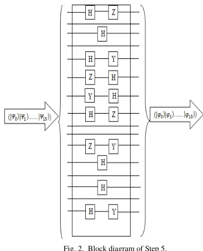
Step 5: Non-Orthogonality
The algorithm will overcome the weakness of the
orthogonality of the states produced in the previous steps by using quantum gates; namely Pauli gates (Y and Z) and Hadmard gate (H), which will make the ciphertext states produced from this step non-orthogonal. A new ciphertext block (|.|. ……|. ) is generated from the output of step 4 (|+|+ ……|+ ) as shown in Fig. 2.
C. Decryption Process
The sequence of steps in the decryption process is directly the reverse of those of the encryption process. Because the above quantum operations are unitary, the decryption process can be completed easily under the guidance of the pre-shared keys.
IV. OUTPUT STATES ANALYSIS AND SECURITY ANALYSIS OF THE PROPOSED ALGORITHM
The algorithm is simulated by the aid of the commercial software (MATHEMATICA Ver.5.2) and QuCalc package. QuCalc is a quantum computation package provided by the University of Montrial, Canada.
A. Output States Examination
For a message block m =19 and the set of shared keys
=3 , =9 , *=7, the results of running our program are detailed below.
The binary representation of m is
= {1,1,0,0,1,0,0,0,0,0,0,0,0,0,0,0}
Step 1 result:
= {0,0,0,1,1,0,0,1,0,0,0,0,0,0,0,0}
Step 2 result:
= {0,0,0,0,0,1,0,0,0,0,0,1,0,0,0,1}
Step 3 result:
' =
[image:3.595.321.527.217.471.2] [image:3.595.52.260.341.543.2]{|0, |0, |0, |0, |0, |1, |0, |0, |0, |0, |0, |1, |0, |0, |0, |1}
) =
{|1, |0, |0, |0, |0, |1, |1, |0, |0, |0, |0, |0, |1, |0, |0, |1}
Fig. 1. Block diagram of Step 3.
Step 4 result:
+ =
{|0, |1, |0, |0, |1, |0, |0, |1, |1, |0, |0, |0, |0, |1, |0, |0}
Step 5 result:
. =
{|0, |+, |0, |+, |1, −|−, |0, −|−, |+, |0, |+, |−, |+, |0, |0, −|−}
The state of the quantum system is given as:
. = {1102 ⊗ 4 1 √2
1 √2
7 ⊗ 1102 ⊗ 4 1 √2
1 √2
7 ⊗ 1012 ⊗ 4 − √2 √2
7
⊗ 1102 ⊗ 4 −1 √2 1 √2
7 ⊗ 4 √2
√2
7 ⊗ 1102
⊗ 4 1 √2
1 √2
7 ⊗ 4 1 √2 −1 √2
7 ⊗ 4 1 √2
1 √2
7 ⊗ 1102
⊗ 1102 ⊗ 4 − √2 √2
7}
In Table I, sample message blocks and the resulting ciphertext quantum states are summarized for further verification of the implementation of the algorithm and ensuring non-orthogonality of the resulting states.
Moreover, an exhaustive search for all possible output states showed that the following seven states are only obtainable:
|0 , |1 , |+ , |− , − |− , |+ , |−
B. Security Analysis
A simulation program is used to evaluate all possible system states produced by the algorithm which are 524288 (219) states. Thus, the mapping from message bits blocks to ciphertext qubits blocks is one to many. The quantum system may be in the states (|.|. ……|.899) with equal probabilities : =
899.
One may calculate the density matrix from the relation:
∑
ϕ ϕ= ρ
i
i i i
p
where ϕi ϕi denotes the outer product of the two states. It is found that
ρ
=;*;<;*;×;*;
where <;*;×;*; is the identity matrix of dimension 65536 × 65536 (216 × 216) and 216 is the dimension of the message block space. Thus, the ciphertext states are homogenous and include no plaintext information. Therefore, the proposed quantum encryption algorithm has perfect secrecy.
The obtained density matrix ρ has the following properties: • All its eigenvalues equal λi = ;*; where i ∈ (1, 2,
……, 65536). It is noted that the eigenvalues are all non-negative real numbers and sum to 1.
• ρ is Hermitian i.e., ρ† = ρ
The inner product between the states |. and |., denoted by >.?.@, is calculated and found to be >.?.@ ={;8,
9√}. These values indicate that the different ciphertext
states are non-orthogonal. Due to the principles of quantum mechanics, the non-orthogonal states cannot be reliably distinguished. The algorithm makes the ciphertext states non-orthognal and hence the ciphertext states are undistinguishabe, which can prevent eavesdropping attacks [4,5]. This ensures the failure of a Trojan horse attack against the proposed encryption scheme, where an injected Trojan horse in either the receiver's or sender's apparatus fails to provide any feedback when a qubit is in either state
+
or−
.Finally, since the mapping of message bits blocks to the ciphertext qubits blocks is one to many depending on the choice of the set of keys, then a brute force attack against the proposed scheme cannot be used to infer the key set used and the keys are distinct for different message blocks. Hence, the proposed scheme is resistant to a brute force attack.
V. DISCUSSION
The proposed encryption algorithm is compared to two related schemes in Table II to demonstrate its competitiveness to these schemes.
It is clear from this comparison that the proposed algorithm has smaller cost compared to the algorithm in [5] as a fewer number of key groups is used and a smaller number of blocks is handled, yet both have comparable security. The use of permutations and rotations based on a variable key for each message block increases the security of the proposed algorithm compared to the scheme in [4]. TABLEI
SAMPLE OUTPUT STATES CORRESPONDING TO RANDOMLY CHOSEN
MESSAGES
Message state = 8,
= 7, *= 11
Ciphertext state when
0000000000100111 |+|0|1|+|+|+|0 − |−|+|0−|−|0|+|1|+|1
1101101011101010 |+|0|0|+|−|+|1|+|+|0|+|0|+|0|−|1
0001011110011011 −|−|0|1|−| + |−|0− |−|+|1|+|1|−|1|−|0
0000100100110110 |+|0|1|+|+|−|1 − |−|+|1−|−|1|+|1|+|1
VI. CONCLUSION
In this paper, a new quantum encryption algorithm is presented. It proceeds in two parts: the first manipulates input message bits and the second applies quantum gates to the partially encrypted message qubits. According to the no-cloning theorem, eavesdropping is detectable in case of encoding a transmitted message as quantum bits instead of classical binary digits. Thus, more security is imposed on the system.
A detailed analysis of the algorithm results has been provided. The algorithm enlarges the message space as for a 16-bit block, the output space has a dimension of 219 instead of just 216. The output states are non-orthogonal rendering a Trojan horse attack unsuccessful against the proposed algorithm and the output contains no plaintext information due to the fact that the ciphertext (or output) space is homogeneous. The proposed scheme represents a good tradeoff between efficiency and security compared to other schemes in literature.
REFERENCES
[1] Menezes, P. Oorschot and S. Vanstone, Handbook of Applied Cryptography, CRC Press, 1996.
[2] A. Chatterjee, "Introduction to Quantum Computation", ePrint archive: http://arxiv.org-/abs/quant-ph/031211,december2005. [3] CH Bennet and G. Brassard, "Quantum Cryptography: Public Key
Distribution and Coin Tossing", Proceedings of the International Conference on Computers, Systems and Signal Processing, Bangalore, India 2004.
[4] N. Zhou, G. Zeng, Y. Nie, J. Xiong and F. Zhu, "A Novel Quantum Block Encryption Algorithm Based on Quantum Computation", Physica A: Statistical Mechanics and its Applications, Vol. 362, Issue 2, 1 April 2006, pp. 305-313.
[5] Amr Yousef, A New Symmetric Cryptographic Algorithm Based on the Quantum Computation, Master Thesis,University of Alexandria, Egypt, 2006.
[6] Z. Cao and L. Liu, Improvement of One Quantum Encryption Scheme, Proceedings of the IEEE International Conference on Intelligent and Computing Systems (ICIS), vol. 1, pp. 335-339, 2010. [7] V. Karimipour and M. Asoudeh, "Quantum Secret Sharing and
Random Hopping: Using Single States Instead of Entanglement", Journal of Physical Review A, American Physical Society, vol. 92, 2015.
[8] D. S. Sundar and N. Narayan, "A Novel Voting Scheme Using Quantum Cryptography", 2014 IEEE Conference on Open Systems (ICOS), Subang, pp. 66-71, 2014.
[9] B. Patterson, Quantum Gates, URL http://www.cs.iastate.edu/
[10] Fraunhofer Quantum Computing Simulator, URL
http://www.qc.fraunhofer.de/
TABLEII
COMPARATIVE STUDY BETWEEN PROPOSED ALGORITHM AND RELATED
SCHEMES IN LITERATURE
Algorithm in [4] Algorithm in [5] Proposed algorithm Message
block size 2-bits 10-bits 16-bits Number of
keys 4 10 3
State of keys Fixed Vary for each block
Vary for each block
Privacy
Homogeneous and no plaintext information
Homogeneous and no plaintext information
Homogeneous and no plaintext information
Inner product between
output states (1 + √2)/16 {
;,8√} {;8,9√}
Orthogonality of output states
Non-orthogonal states
Non-orthogonal states
Non-orthogonal states
Trojan horse