Abstract—This paper investigates a digital controller based dual active full bridge phase shift (DAFBFS) DC/DC power converter for performing advanced energy management and control functions in renewable energy based power generation systems, e.g., wind and solar power generation systems. The hardware of the proposed DAFBFS DC/DC converter includes two full-bridge circuit units, a coupling inductor and a high-frequency transformer, especially designed for fast charging and discharging control of a battery based energy storage system (BESS). The proposed DAFBFS converter has a number of merits, i.e., electrical isolation, high voltage gain, fast response feature in current regulation and simplicity in designing controllers with a single control variable. To achieve a better efficiency and enhance functional flexibility in hardware implementation, a fully digital control scheme with a TI DSP as the core controller is developed and verified. Typical simulation and experimental results are presented to demonstrate the performance of the proposed control scheme.
Index Terms—renewable energy, dc/dc converter, digital controller, battery energy storage system
I. INTRODUCTION
N recent years, the renewable energy based distributed power generation (DG) has become the most economic option for new power generation capacity, especially for countries that mainly depend on nuclear energy, natural gas, coal and fuel oil for power generation, such as Taiwan and other countries in Asia[1-3]. It has been well accepted that a self-sufficient, domestic renewable energy based power generation system has a number of advantages, e.g., it increases energy security, eliminates the need for expensive fuel imports, and reduces the burden on national budgets. It can also create substantial economic and societal benefits, such as increasing national competitiveness and job creation level apart from its global environmental benefits. In Taiwan, the goal of DG using renewable energy based power generation devices, e.g., wind turbine generators (WTG) and photovoltaic (PV) modules, is to meet the continuously growing electric power demand without increasing greenhouse gas emissions and to gradually reduce nuclear energy based power generation. It should be noted that due to the intrinsic feature of power fluctuation in most renewable generation systems, e.g., WTG and PV the
Manuscript received January 6, 2017; This work was supported in part by the Ministry of Science and Technology, R.O.C. under Grant MOST 105-2221-E-239-022.
C. T. Ma is with the Dept. of Electrical Engineering, CEECS, National United University, Miaoli, 36063 TAIWAN (corresponding author: +886-37-382482; fax: +886-37-382488; e-mail: [email protected]).
dispatching of their output power is quite difficult and even impossible[4,5]. Therefore, the addition of certain battery energy storage systems (BESS) with real-time charging and discharging capabilities is indeed necessary to increase the power management and control flexibility of future power systems embedded with a high penetration level of DG.
Over the last decade, the development of high-performance BESS[6,7]and the related advanced power management and control technologies have enabled the fast development of renewable energy applications and so-called intelligent, hybrid DC/AC micro-grids[8,9]. In the design of grid-level BESS, a number of conventional batteries can be chosen; however, the all vanadium redox flow battery (VRFB) has a number of intrinsic merits; e.g., its output power and capacity can be independently designed; the charging and discharging functions can be carried out simultaneously; it can be fully discharged without any harm; it has a high energy-conversion efficiency; it takes into account the safety and environmental protection concerns and above all, its system maintenance cost is relatively low[10,11]. With the above advantages, the VRFB system is very suitable for applications in a wide variety of DG to optimize the integration of energy management and power quality control techniques. In addition, any advanced BESS must be equipped with advanced power converters and the related system control algorithms to achieve satisfactory performance.
Considering the required energy management and control functions in wind and solar power generation systems, a digital controller based dual active full bridge phase shift (DAFBFS) DC/DC power converter with fast current regulation capability is investigated in this paper. To confirm the correctness of the proposed control scheme, several simulations cases are carried out on PSIM software and an 1.2 kW hardware system with the TMS320F28335 as core controller and the related hardware interface circuits are also constructed for practical evaluations. The arrangement of sections in this paper is as follows. In section II, the main topology of isolated DC/DC power converters are briefly reviewed. The operating principles and control schemes of the proposed DAFBFS power converter are then addressed in section III. In section IV, a fast charging and discharging control case is stated and typical results obtained from simulation studies and experimental tests are presented with brief discussions. Section V gives a short summary on the technical issues concerned and the performance of the DAFBFS power converter with the proposed control scheme.
Design and Implementation of a Bidirectional
DC/DC Converter for BESS Operations
C.T. Ma, Member, IAENG
II. THE TOPOLOGIES OF DC/DCCONVERTERS
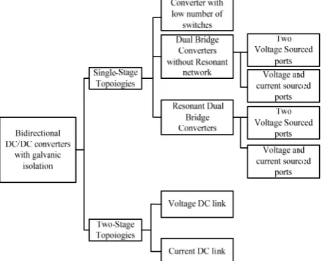
[image:2.595.306.547.136.223.2]In the open literature, there are a lot of research and discussions on bidirectional DC/DC converters. Many research results have been presented [12,13]. Bi-directional DC/DC converters can be simply classified into non-isolated and isolated converter topologies according to whether they have a transformer. Fig. 1 shows the classification of bi-directional DC/DC converters. In this section, only some of the isolated bi-directional DC/DC converters presented in the literatures are reviewed.
[image:2.595.48.281.180.367.2]Fig. 1 The classification of bi-directional DC/DC converters.
Fig. 2 shows the typical structure of isolated bidirectional DC/DC converter [14]. As can be seen in Fig. 2, a high-frequency transformer connects the two sets of inverters with their own filtering capacitors and inductors. Because the transformer is a non-ideal component the effects of leakage inductance on voltage spikes appear, making it not suitable for high power applications.
Fig. 2. The isolated bidirectional DC/DC converter.
In paper [15], the authors proposed a revised version of the circuit shown in Fig. 2 to improve the above mentioned drawback by adding a RCD circuit to the output side of the secondary bridge. As shown in Fig. 3, the RCD circuit can be used to absorb the energy released by the leakage inductance of the transformer, to reduce the voltage spike during switching of the four switches and to achieve the possibility of high power operation.
[image:2.595.306.549.392.472.2]
Fig. 3. The isolated bidirectional DC/DC converter with a RCD circuit.
However, the use of RCD circuit will lead to additional losses, resulting in the decrease of overall efficiency of the converter. Therefore, the authors of paper [16] proposed a low-loss damping circuit as shown in Fig. 4, which can be operated in high-power application conditions and at the same time with relatively high system efficiency.
Fig. 4. The low-loss isolated bidirectional DC/DC converter circuitry.
To further improve the overall performance of the above mentioned converters, the damping circuit in Fig. 4 was replaced by an active clamping circuit, in which the rectifier bridge’s output side of the converter is connected in parallel with a switch and a series capacitor and finally connected to the filtering inductor and capacitor by the authors of [17] as shown in Fig. 5. This arrangement has the following advantages:1) zero-voltage switching for the first two switches on the secondary side; 2)zero voltage and zero current switching for all switches on the primary side of the transformer; 3)no circulating currents.
[image:2.595.48.285.478.556.2]
Fig. 5. The isolated bidirectional DC/DC converter with an active clamping circuit.
Theoretically, bidirectional DC / DC converters with active clamped buffer circuits have higher conversion efficiency compared to conventional full-bridge phase-shift converters; however, power switches of the circuit is required to withstand a relatively higher voltage stress than its secondary voltage, Vd2. To eliminate this shortcoming, the authors of paper [18] improved the circuit architecture of Fig. 5, by changing the primary-side full-bridge into a half-bridge topology, as shown in Fig. 6. This arrangement has the following advantages:1) zero voltage switching for all switches; 2) constant clamping voltage on all switches; 3) simplicity in designing driving circuits.
[image:2.595.306.548.668.749.2][image:2.595.47.283.681.756.2]
III. THE OPERATING PRINCIPLES OF THE PROPOSED DC/DC CONVERTER
A. The Operating Principle of DAFBFS converters
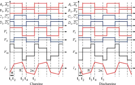
The transformer isolated DAFBFS DC/DC converter investigated in this paper uses an energy transferring inductor and the output capacitors of its power switches to achieve zero voltage switching. This converter topology is very suitable for application scenarios in DG systems since it provides power isolation, high voltage conversion ratio, and high efficiency. The DAFBFS DC/DC converter with a simplified VRFB model is shown in Fig. 7. The primary side of the transformer connecting to a full-bridge converter of four active switches, whose DC side is normally connected to a DC bus as considered the high-voltage side. The secondary side full-bridge converter is connected to a VRFB as the low-voltage side. In operation, the DAFBFS DC/DC converter is controlled with a 50% conduction period and a bipolar PWM switching signal. By controlling the active switches of the primary and secondary sides, a phase shift, θ, can be produced between the two voltage waveforms across the energy transferring inductor, V1 and V2. The resonance inductor, L, here, is acting as a transferring media for a bidirectional energy transmission, thereby controlling the direction and magnitude of power flows with the changing of θ. Fig. 8 shows the theoretical waveforms of the operations of charging and discharging of the VRFB.
1
V IL V2
N d V r T o1 C VRFB V 1 A 2
A B2
1
B C1
[image:3.595.309.544.247.318.2]2 C 1 D 2 D o2 C 3 V
Fig. 7. The isolated DAFBFS DC/DC converter with a simplified VRFB model.
Charging Discharging
Fig. 8. The theoretical waveforms of the DAFBFS converter charging and discharging of the VRFB.
B. Control of the DAFBFS DC/DC Converter
Because the battery unit, the VRFB used in this paper is connected to the secondary side of the DC/DC converter and normally a DC bus is connected to the primary side of
DAFBFS DC/DC converter. Therefore, it can be viewed as two ideal DC voltage sources connected to both sides of the converter. The DAFBFS DC/DC converter can then control the power flow in both directions by simply changing θ. In this control scheme, both voltage sources remains almost constant, only the current magnitude and direction are changed, thereby changing the power magnitude and direction as desired. In practical design, the derivation of the mathematical model of the converter must include the gain parameters of current sensor and the internal phase-shift generator. After some mathematical derivations, the control block diagram of a type-II PI controller GI(s) used for simulation studies and the DSP based experimental tests carried out in this paper is directly shown in Fig. 9. The overall control system is shown in Fig. 10.
dc i dfb i s k I
G Vcon
[image:3.595.307.545.360.490.2]d I I H kθ − 0 4 cos o NV sL θ π − θ
Fig. 9: The control block diagram of a type-II PI current controller for the DAFBFS DC/DC Converter.
1
V IL V2
2 N 1 N d V r
T Co
VRFB I 0° = A 180° = B θ° = C
(θ+180)°
= D VRFB V Phase-shift θ VRFB
arg , arg
Ch ing Disch ing
I
VRFB
[image:3.595.56.287.388.495.2]I
Fig. 10: The overall charging and discharging control system of the DAFBFS DC/DC converter.
IV. THE SIMULATION AND EXPERIMENTAL RESULTS In this section, a fast charging and discharging control function of the DAFBFS DC/DC converters is firstly verified with simulations on the PowerSIM (PSIM) software, followed by a practical test using a small-scale experimental hardware setup with the same operation conditions. The test system parameters are: DC Bus has a voltage of 200V, the rated voltage of VRFB is 48V. The power rating of the DAFBFS converter is 1.2kW.The final PSIM model for simulation studies is shown in Fig. 11.
A. Simulation Results of DAFBFS converters
[image:3.595.51.287.539.687.2]V
Vb
DSP Config F28335
Hardware F28335 Config 0.05
1
z
5 20
46u
47u
-90 90
V1 V2
0.05 V3
48 0.25
Config SCI F28335
F28335 SCI
in
F28335 SCI
in
fix_Ioc pwms
Vos
K K
H(z) V
Vd
A IL
A Is
emph
pwms
Ios 0
PS_theta
PS_theta
1
z
F28335 SCI
in
Select_con_mode 200
0.5
K K
0.06 Vins
DC/DC Converter
Charg./Discharg.controller
[image:4.595.46.271.53.186.2]VRFB DC Bus
[image:4.595.308.533.55.162.2]Fig. 11.The PSIM model of the DAFBFS DC/DC converter.
Fig. 12. A list of continuous charging and discharging commands.
Fig. 13 (a). A list of continuous charging and discharging commands (simulated).
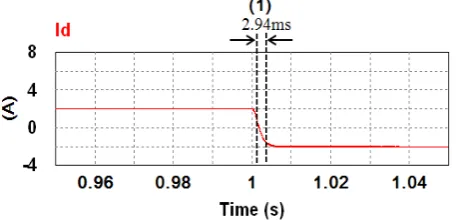
Fig. 13 (b). Results of a step change in current command, from 2A to -2A with the falling time of 2.94ms.
Fig. 13 (c). Results of a step change in current command, from -2A to 2A with the rising time of 2.57ms.
Fig. 13 (d). Results of a step change in current command, from 6A to -2A with the falling time of 2.72ms.
Fig. 13 (e). Results of a step change in current command, from -2A to 6A with the rising time of 3.09ms.
Fig. 13 (f). Results of a step change in current command, from 3A to -2A with the falling time of 2.86ms.
Fig. 13 (g). Results of a step change in current command, from -2A to 3A with the rising time of 2.63ms.
B. Experimental Results of DAFBFS converters
[image:4.595.313.532.210.326.2] [image:4.595.54.286.229.328.2] [image:4.595.56.279.371.467.2] [image:4.595.312.536.377.493.2] [image:4.595.51.281.504.614.2] [image:4.595.306.536.541.655.2] [image:4.595.51.286.649.752.2]conditions are the same as that used in the simulation case presented in subsection A.
[image:5.595.78.266.84.212.2]
Oscilloscope DAFBFS DC/DC Converter
Fig. 14. The hardware setup of an 1.2 kW DAFBFS converter system.
Ch4:2A/div Time:1s/div
(1) (2) (3) (4) (5) (6)
Fig. 15 (a). A list of continuous charging and discharging commands (measured).
Ch4:2A/div Time:10ms/div
(1)
Fig. 15 (b). Results of a step change in current command, from 2A to -2A with the falling time of 2.0ms.
Ch4:2A/div Time:10ms/div
(2)
Fig. 15 (c). Results of a step change in current command, from -2A to 2A with the rising time of 2.4ms (measured).
Ch4:2A/div Time:10ms/div
(3)
Fig. 15 (d). Results of a step change in current command, from 6A to -2A with the falling time of 2.6ms (measured).
Ch4:2A/div Time:10ms/div
(4)
Fig. 15 (e). Results of a step change in current command, from -2A to 6A with the rising time of 4.2ms (measured).
Ch4:2A/div Time:10ms/div
(5)
Fig. 15(f). Results of a step change in current command, from 3A to -2A with the falling time of 2.0ms (measured).
Ch4:2A/div Time:10ms/div
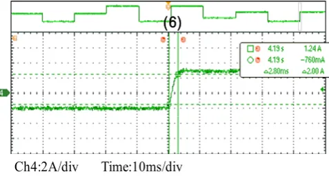
(6)
[image:5.595.308.548.88.216.2] [image:5.595.49.288.251.397.2] [image:5.595.307.549.259.388.2] [image:5.595.306.548.433.560.2] [image:5.595.49.291.442.567.2] [image:5.595.308.547.606.734.2] [image:5.595.48.287.613.741.2]V. CONCLUSION
The output power fluctuation of renewable energy based DG systems is unavoidable. Without adequate control schemes, the power fluctuation phenomena is prone to make the grid voltage and frequency unstable and degrade the quality of electric power supply system. It has been proved that using a properly designed BESS with fast-response power converter systems and appropriate power control strategies can effectively solve the problem. In the aspect of fast-response power converter systems, this paper has firefly reviewed the potential topologies of bidirectional DC/DC power converters and proposed a simple phase-shifting power control scheme. The overall performance of a selected DAFBFS DC/DC power converter acting as the charging and discharging interface of a BESS is fully investigated in this paper. The feasibility and effectiveness of the proposed fast current control method based on a single phase-shifting parameter has been verified with simulation studies and tests with small-scale experimental hardware setup. Typical results obtained from both simulation and practical measured waveforms have been presented with brief discussions.
REFERENCES
[1] L. F. Ochoa, G. P. Harrison, "Minimizing energy losses: Optimal accommodation and smart operation of renewable distributed generation", IEEE Trans. Power Syst., vol. 26, no. 1, pp. 198-205, Feb.
2011.
[2] D.Q. Hung, N. Mithulananthan, “DG allocation in primary distribution systems considering loss reduction,” Handbook of renewable energy technology (World Scientific Publishers, Singapore),pp. 587–628, 2011.
[3] I. El-Samahy, E. El-Saadany, "The effect of DG on power quality in a deregulated environment", Proc. IEEE Power Eng. Soc. Gen. Meet., vol.
3, pp. 2969-2976, 2005.
[4] L. Xiangjun, H. Dong, L. Xiaokang, "Battery energy storage station (BESS)-Based smoothing control of photovoltaic (PV) and wind power generation fluctuations", IEEE Trans. Sustainable Energy, vol. 4, no. 2, pp. 464-473, Apr. 2013.
[5] R. Sebastián, “Application of a battery energy storage for frequency regulation and peak shaving in a wind diesel power system,” IET Generation, Transmission & Distribution, vol. 10, no. 3, pp.
764–770,Feb. 2016.
[6] M. Farhadi and O. Mohammed, “Energy Storage Technologies for High-Power Applications”, IEEE Transaction on Industry Applications, Vol. 52, No. 3, pp:1953 – 1961, May/June 2016. [7] M. Zidar , P. S. Georgilakis , N. D. Hatziargyriou , T. Capuder and D.
Skrlec , “ Review of energy storage allocation in power distribution networks: applications, methods and future research ,” IET Generation, Transmission & Distribution , vol. 10 , no. 3 , pp. 645 – 652 , 2016 .
[8] A. Chaouachi, R. M. Kamel, R. Andoulsi, K. Nagasaka, "Multiobjective intelligent energy management for a microgrid," IEEE Trans. Ind. Electron., vol. 60, no. 4, pp. 1688-1699, Apr. 2013. [9] M. Kumar, S. C. Srivastava, S. N. Singh, M. Ramamoorty,
"Development of a control strategy for interconnection of islanded direct current microgrids", IET Renew. Power Gener., pp. 1-13, Sep. 2014.
[10] M Guarnieri, P Mattavelli, G Petrone and G. Spagnuolo, “Vanadium Redox Flow Batteries: Potentials and Challenges of an Emerging Storage Technology,” IEEE Industrial Electronics Magazine., vol.10, no. 4, pp. 20-31, Dec.2016.
[11] R D‘Agostino, L Baumann, A Damiano and E Boggasch, “A Vanadium-Redox-Flow-Battery Model for Evaluation of Distributed Storage Implementation in Residential Energy Systems,” IEEE Transactions on Energy Conversion, vol. 30, no. 2, pp. 421-430,
Jun.2015.
[12] S. Bhattacharya, T. Zhao, G.Wang, S. Dutta, S. Baek,Y.Du, B. Parkhideh,X. Zhou, and A. Q. Huang, “Design and development of generation-isilicon based solid state transformer,” in Proc. 25th Annu.
IEEE Appl.Power Electron. Conf. Expo., Palm Springs, CA,, pp.
1666–1673, 2010.
[13] S. Inoue and H. Akagi, “A bidirectional isolated dc-dc converter as a core circuit of the next-generation medium-voltage power conversion system,”IEEE Trans Power Electron., vol. 22, no. 2, pp. 535–542, 2007.
[14] O. Garcia, L.A. Flores, J.A. Oliver, J.A. Cobos and J. de la Pena, “Bidirectional DC-DC Converter For Hybrid Vehicles,” IEEE Power Electronics Specialists Conference, pp.1881-1886, June 2005.
[15] L. Zhu, “A Novel Soft-Commutating Isolated Boost Full-bridge ZVS-PWM DC-DC Converter for Bi-directional High Power Applications,” IEEE Power Electronics Specialists Conference, vol. 3,
pp.2141-2146, June 2004.
[16] E.S. Kim, K.Y. Joe, H.Y. Choi, Y.H. Kim and Y.H. Cho, “An Improved Soft Switching Bi-directional PSPWM FB DC/DC Converter,” IEEE Industrial Electronics Society, vol. 2, pp.740-743, September 1998.
[17] R. Li, A. Pottharst, N. Fröhleke, J. Böcker, K. Witting, M. Dellnitz, O. Znamenshchykov and R. Feldmann, “Design and Implementation of a Hybrid Energy Supply System for Railway Vehicles,” Twentieth Annual IEEE Applied Power Electronics Conference and Exposition, vol. 1, pp.474- 480, March 2005.