1
Abstract—This paper reports a multilink suspension analysis aimed to improve the performances in terms of car handling or comfort, by acting on the components of the suspension itself. In particular the analysis focuses on the effects produced on the suspension characteristic curves by some modifications in rods length.
The technique can be adopted in the design phase of a multilink suspension to obtain a desired characteristic, in terms of camber or steering, by optimizing the proper length of each single rod.
Index Terms — multilink, car suspensions, kinematical analysis
I. INTRODUCTION
HE road vehicles need to constantly maintain contact with track while ensuring a reasonable level of comfort for passengers. Moreover, since ancient times, it is well known the importance for any type of terrestrial vehicle, both in civil and military fields, to be equipped with a suitable mechanism which allows to follow correct trajectories, in presence of particularly uneven road surfaces [1].
The above requirements can be achieved through the use of a suitable suspension system.
The use of multi-link suspensions on cars is today widely diffused allowing good performances both in terms of handling and comfort. The regulation of this two characteristics can be properly done by setting the geometrical parameters and compliances of the suspension.
In the design phase of a vehicle it would be useful to dispose of information about the possible effects on the vehicle dynamic produced by the variation of some parameters such as the suspension rod length or the bushing compliances [2,3].
The multi-link suspensions are mechanisms with one d.o.f., constituted by five rods, each one eliminating one d.o.f., connecting the wheel carrier to the car body, through joints that, in the most general case, can be considered as spherical [2,5].
The joints’ compliance contributes to the ride comfort thanks to the capability of absorption of the forces deriving
Manuscript received March 6, 2016; revised April 14, 2016.
Ernesto Rocca is with Dipartimento di Ingegneria Industriale, Università degli Studi di Napoli Federico II, via Claudio n. 21 80125 Napoli Italy (e-mail: ernesto.rocca@unina.it).
Francesco Timpone is with Dipartimento di Ingegneria Industriale, Università degli Studi di Napoli Federico II, via Claudio n. 21 80125 Napoli Italy (corresponding author: phone: +39 081 76 83263; fax: +39 081
2394165; e-mail: francesco.timpone@unina.it).
from the unevenness of the road. For a correct adjustment of the compliance of these components may be also possible to assign to the suspension, under dynamic conditions, some appropriate displacements or a particular steering effect to improve the stability of the vehicle [6, 7].
The study of the mechanism, firstly, can be conducted under the hypothesis that all the elements, i.e. rods, wheel carrier and joints, are rigid.
In the present paper, with reference to a rear car suspension, an iterative procedure is described, that enables to develop kinematical and static analyses under the hypothesis of rigid rods and joints.
The procedure allows to draw the whole characteristic curves of the suspension.
The aim of the paper is to analyze the kinematical behaviour of this type of suspension by varying the lengths of the rods, in particular by varying the joints coordinates on the chassis, and keeping constant the joints positions on the wheel carrier. In this way it is possible to analyze how the length of a single link can influence a particular characteristic of the suspension.
This technique could be particularly useful in an identification procedure, during the design stage of a new suspension, starting from a desired characteristic, as example in terms of camber or steering curves, to identify the correct length of each single rod of the suspension itself.
II. KINEMATIC ANALYSIS
A. The multilink suspension model
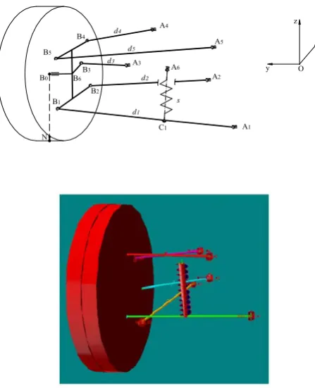
The analysis considers a multi-link suspension (fig. 1) with 5 rods and a spring interposed between the car body (A6) and the lower link d1 (C1). The system presents then 6
spherical joints on the car body and 5 on the wheel carrier. This kind of mechanism refers in particular to a vehicle rear suspension.
Considering the hypothesis of rigid links and with no clearances in the joints, this mechanism has one d.o.f.
It is therefore possible to assume the spring extension s, as the independent co-ordinate, and a frame Oxyz fixed to the car body as the base co-ordinate system.
The kinematics of this mechanism can be resolved through a vectorial method [2, 3, 4], also used in the study of parallel mechanisms with one d.o.f., of the Stewart platform type. This analogy is legitimate since the wheel carrier displacements are comparable to the displacements of a platform with respect to a base that, in the specific case of the suspension, is represented by the vehicle body.
Analysis of Multilink Suspension
Characteristics due to the Rods Length
Variations
Ernesto ROCCA, Francesco TIMPONE
in Appendix.
The kinematic analysis then makes it possible to obtain the trajectory of any point of the suspension, and in particular, of the wheel centre B0, or of the wheel-road
contact centre N, in the reference fixed to the vehicle body.
Fig.1 The multi-link suspension scheme
Moreover, the steering and the camber angles for a suspension rebound can be obtained. The numerical procedure evaluates the reactions in the links by applying in the point N a vector of external forces which resultant and moment are respectively F and M. The spring reacts so with a force: Rc1=Ks s.
B. The numerical analysis
The unknown value of s, that gives equilibrium at the system, can be calculated by a iterative procedure that converges through the resolution of the following vector equation system:
0 ˆ ˆ ˆ ˆ ˆ ˆ ˆ ˆ ˆ
0 ˆ ˆ ˆ ˆ ˆ ˆ
5 15 5 4 14 4 3 13 3 2 12 2 0 10 0
5 5 4 4 3 3 2 2 7 17 1 11 0
d b R d b R d b R d b R F b M
d R d R d R d R d R d R F
B B
B B
B B B B B B
fig. 2), while F0,M0 are the external forces in static position, and dˆ e i bˆ indicate the versors of vectors ij di AiBi e
j iB
B
ij
b .
The numerical code starts from the following input data: • Co-ordinates of the Ai points, which are the joint centre
situated on the chassis, in the base reference frame;
• Co-ordinates of the Bi points, which are the joint centre situated on the wheel carrier, in the reference frame fixed to the latter;
• The rods lengths di;
[image:2.595.306.542.118.358.2]An example of the results is reported in fig. 3 where the trajectories described by the point N, i.e. the wheel-road
Fig. 3 Trajectories described by the N point in longitudinal Oxz (a) and transversal Oyz (b) plane
[image:2.595.52.276.146.422.2]contact centre, both in the longitudinal Oxz and the transversal Oyz reference plane, for a vehicle rear suspension whose parameters are reported in the tables 1,2.
[image:2.595.310.541.235.344.2]Table 1 – link coordinates in the Oxyz reference
Table 2 – wheel carrier and suspension parameters
The suspension model, in a previous analysis, has been numerically validated by using a multibody dynamics code (ADAMS) employed as a sort of “experimental” data source in order to test the accuracy of the theoretical code [3].
-10 -5 0 5 10 15 20 25
X (mm) -100
-80 -60 -40 -20 0 20 40 60 80 100
Z
(m
m
)
675 680 685 690 695 700 705 710 715 720
Y (mm) -100
-80 -60 -40 -20 0 20 40 60 80 100
Z
(m
m
)
x y x x y z
A1 -102 205 231 B1 -43. 662. 208. A2 321 496 251 B2 44. 632. 163. A3 209 404 296 B3 141. 666. 269. A4 209 437 402 B4 78. 662. 397. A5 -5 356 416 B5 -5. 666. 427. A6 -109 428 411 B6 -.4 605 300.5
x y z C1 -72.5 433.5 219.5 B0 0. 705. 302.
Spring stiffness: Ks 60 (N/mm)
Spring free length: s0 282 (mm)
Tired wheel radius: R 302 (mm)
wheel and wheel carrier total mass: m 30 (kg)
B6 B0
N B1
B2 B5
B3
C1
Fy
Fz
Fx
Mz
My
Mx
B4 RB4
RB5
RB3
RB2
RB11
RB17
RB2
RB11
RB17
RC1
RA11
RA17
A6
Fig.2 Forces on wheel and on link-1
A1
A2
A3 A
6
B1
B2
B3
B5
C1
B0 B6
N
x
y z
O
d1
d2
d3
d4
d5
s A4
A5
[image:2.595.63.293.620.717.2]III. VARIATION OF THE ROD LENGTHS
In order to conduct an analysis about the performances of the system under investigation, when varying the lengths of the suspension rods, a numerical procedure has been implemented under the following hypotheses: no-compliances in the joints and rigid rods. In the multi-link suspension only link d1 has been kept unchanged in length and location, because it is connected to the suspension spring. The length of all the other links has been varied, in turns, to see what characteristic is more influenced, and so to see how vary the performances of the entire suspension system.
Starting from the assigned original geometry of this suspension, provided by an actual design project, the coordinates of the joints in correspondence of the chassis have been modified by increasing or decreasing the rod length of links d2, d3, d4 and d5, keeping constant their
direction, in order to test the effects of such modifications on the characteristic curves. The first rod (link d1) has been
kept in the original position, how above said.
In this study the geometrical parameters related to the attachment points of the links on the chassis have been modified, without modifying the direction of the links themselves in the early configuration; so, the characteristic curves necessary to study the suspension behaviour, have been obtained. Each modified configuration of the suspension represents a mechanism cinematically and geometrically different from the previous one, but it is characterized by the same values of camber and steer angle in the nominal original configuration with respect to the early position.
In particular the numerical analysis has been conducted by varying in turn the lengths of each link, in lengthening and in shortening, of 4 cm by steps of 0.5cm.
IV. RESULTS OF THE ANALYSIS
The numerical investigation presented in the paper has been carried on by means of a code for kinematical analysis of multilink suspensions developed by the authors. In the following figures the various characteristics in terms of steer angle, camber angle, wheel base and wheel track have been reported as a function of the rod length, assuming as 0 the starting original length. The coordinates and the lengths of each single link are reported in tables (the coordinates and the relative length of the links in the early unmodified configuration are highlighted in green).
Many characteristics in terms of steer, camber, wheel base variation, semi-track, have been performed for each configuration of the modified system. In the following figure the characteristic curves of the multilink modified in the links d2, located in the lower part of the suspension
system, have been reported. Figure 4 and 5 report, as an example, the curves of steer and camber angle for the modified configurations of the rod d2.
[image:3.595.306.555.64.147.2]Tables 3 and 4 reassume the percent variations of the steer angle characteristic in rebound and in bumps showing a large sensitivity especially in the latter movement.
Fig.4 Steer angle values for different rod-d2 lengths vs. Nz
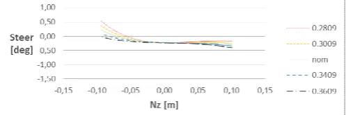
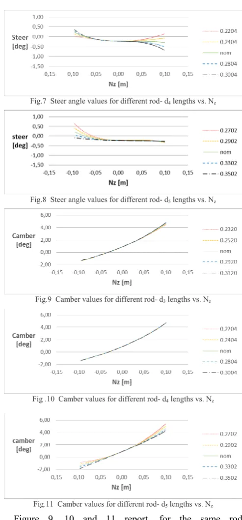
[image:3.595.368.484.398.546.2]Figure 6, 7 and 8 report the characteristic curves of steer angle variations for the modified configurations of the link d3, d4 and d5, respectively.
Table 3 – Parameters variation of the rod d2 for rebound
lenght δ var. (%)
0,3609 -0,0228 -110% 0,3509 0,0326 -86% 0,3409 0,0943 -58% 0,3309 0,1578 -30% 0,3209 0,2265 0% 0,3109 0,2992 32% 0,3009 0,3748 65% 0,2909 0,4568 102% 0,2809 0,5405 139%
[image:3.595.303.553.573.752.2]Table 4 – Parameters variation of the rod d2 for bumps
Fig.5 Camber values for different rod- d2 lengths vs. Nz
Fig.6 Steer angle values for different rod- d3 lengths vs. Nz
lenght δ var. (%)
Fig.7 Steer angle values for different rod- d4 lengths vs. Nz
Fig.8 Steer angle values for different rod- d5 lengths vs. Nz
Fig.9 Camber values for different rod- d3 lengths vs. Nz
Fig .10 Camber values for different rod- d4 lengths vs. Nz
Fig.11 Camber values for different rod- d5 lengths vs. Nz Figure 9, 10 and 11 report, for the same rod modifications, the characteristic curves of camber angle, respectively.
How it can be noted by observing the characteristic curves for the link d2, posed in the lower part of the
suspension, the steer angle varies enough as the length of the rod increases or decreases, while the camber angle seems to be insensitive to this variations. This insensitivity is probably due to the position of the link itself which appears to be quite centered respect the wheel carrier and transversally oriented, so its position doesn’t influence the camber characteristic.
As regard to the link d3 a large variation in the steer angle
is observed, both in rebound and in bumps, due to its spatial position, i.e. almost a “steer rod”. The upper links, d4 and d5,
show a trend similar of the link d2 as regard the steering
characteristic. As regard to the camber angle characteristic, it shows a sensitive variation only in the curves of the
characteristic when the wheel carrier oscillates.
V. CONCLUSIONS
In the paper the behaviour of a multi-link suspension by varying the lengths of the rods has been analyzed, in particular by varying only the joints coordinates on the chassis, in order to understand the influence of the length of a single link on a specific characteristic of the suspension, such as the steer angle and camber.
From the kinematical analysis, conducted by using data coming from a vehicle rear multilink suspension, it has been highlighted the possibility of changing the various characteristic curves, and so the performances in terms of handling, by modifying the length of the various rods, eventually combining their effects.
Generally the position and the length of each link can influence significantly one of the particular characteristics of the suspension.
In particular, for the multilink system examined in the paper, the modifications in rods d3 have shown a very
sensitive variation in the steering characteristic. About the camber variation, the rod d5 seems to be the more influent,
due to its spatial position in the suspension layout.
The technique could be particularly useful in an identification procedure, during the design stage of a new suspension, when starting from a desired characteristic in terms of steer angle or camber, it permits to identify the correct length of each single rod of the suspension itself.
APPENDIX
As reference frame, Oxyz, it is assumed a frame fixed to car body, with axis x and y oriented respectively in the longitudinal and transversal directions (see fig.1). The Eq. (1) projected along the reference frame axes generates a system of 6 algebraic equations. In matrix notation is possible to highlight the unknown forces on the links (RBi
vector).
The vector of the known terms is represented by the external forces, so:
z z y y x x z y x B B B B B B z z z z y y y y x x x x z z z z z z y y y y y y x x x x x x F b M F b M F b M F F F R R R R R R d b d b d b d b d b d b d b d b d b d b d b d b d d d d d d d d d d d d d d d d d d 0 10 0 0 10 0 0 10 0 0 0 0 17 5 4 3 2 11 5 15 4 14 3 13 2 12 5 15 4 14 3 13 2 12 5 15 4 14 3 13 2 12 7 5 4 3 2 1 7 5 4 3 2 1 7 5 4 3 2 1 0 ˆ ˆ ˆ ˆ ˆ ˆ ˆ ˆ 0 0 ˆ ˆ ˆ ˆ ˆ ˆ ˆ ˆ 0 0 ˆ ˆ ˆ ˆ ˆ ˆ ˆ ˆ 0(2)
N
ow the equilibrium in link-1 (fig.2) is solved to obtain the reactions in the A1 joint on the car body, and the RC1spring reaction, starting from the previously calculated reactions RB11 and RB17; indicating with the versor of
6 1
A
C
61
c
, and with c11 the modulus ofc
11
C
1A
1 , itgives:
0
ˆ
ˆ
ˆ
ˆ
0
ˆ
ˆ
ˆ
ˆ
ˆ
61 1 7 17 1 11 7 17 1 11
R
Bd
R
Bd
R
Ad
R
Ad
R
Cc
[image:4.595.306.560.567.641.2]At this stage it is verified whether the spring reaction value Rm, for the assigned deformation s, matches the RC1
value obtained from the solution of Eq. (3).
The procedure is so iterated until the convergence is reached.
ACKNOWLEDGMENT
The authors thank Eng. Marco Di Pilla, Mr. Gennaro Stingo and Mr. Giuseppe Iovino for their fundamental technical support during the testing and bench development stages within the Laboratory of Engineering Department Laboratory of “Università degli Studi di Napoli Federico II”.
REFERENCES
[1] Cesare Rossi, Stefano Pagano - A Study on Possible Motors for Siege
Towers - ASME, Journal of Mechanical Design, Vol. 133, 2011.
[2] Knapczyk, J., Dzierzek, S. - Displacement and force analysis of
five-rod suspension with flexible joints – ASME, Journal of Mechanical Design, vol. 117, pp.532-538, 1995.
[3] E. Rocca ,R. Russo. A feasibility study on elastokinematic parameter
identification for a multilink suspension. Journal of Automobile Engineering, 2002, Vol. 216, p. 153-160.
[4] C. Rossi, S. Savino – “Robot Trajectory Planning by Assigning
Positions and Tangential Velocities”, Robotics And Computer Integrated Manufacturing (2012) doi:10.1016/j.rcim.2012.04.003, vol.29, issue 1, February 2013, pp 139-156, ISSN 0736-5845.
[5] Knapczyk, J., Dzierzek, S. - Displacement analysis of five-rod wheel
guiding mechanism by using Vector Method – Proc. Of 25th ISATA, Florence, v. Mechatronics, p. 920893, pp. 687-695.
[6] Lee D.M.A., Pascoe, D.M. ElMaraghy W.H. – An analysis of the
multi-link independent suspension system – 1993, Int. J. of Vehicle design, vol. 14, n°1, pp.44-58.