Abstract—The FRP sheet has been applied in many fields of
civil engineering structures. The study on the application has been spread out involving of precast concrete structures, such as the application on the connection of beam and column of precast concrete structures. Since the strength of the CFRP sheet is depend on the bonding capacity, it is necessary to apply a vertical U-wrap belt on the main sheet to increase its bonding strength. However, it was reported that the vertical U-wrap belt may cause a prematurely rupture on the fibers of main CFRP sheet. Therefore, the diagonal U-wrap belt was considered to avoid the premature rupture. This paper presents the effect of the diagonal U-wrap belt on the moment capacity of the connection system using CFRP sheet on the beam-column join of precast concrete. A series of specimens with parameter of CFRP sheet belts patterns was prepared. The specimens were subjected by one point load on the beam to create a moment at the connection. Results indicated that the applying of diagonal U-wrap belt on the connection system using CFRP sheet on the beam-column join may avoid a premature rupture of fibers. As the results, the moment capacity of the join increased.
Key words: CFRP sheet, U-wrap, Precast, Beam-Column Joint..
I. INTRODUCTION
HE precast technology is growing to dominate the construction system of the concrete infrastructures. The using of precast technology is one of the best alternatives to speed up the construction time as well as to increase the quality of the structures, The advantages of the precast construction involves reduction in construction time, energy, in site labors as well as more favorable cost-benefit relation, less environmental impact, and greater control and final quality of the structures [1,2]. Fig.1 shows the application of the precast technology in constructions. The precast technology has been developed for building constructions, drainage constructions, and bridges constructions including high way bridges constructions.
In precast technology, the connection is critical factor and one of the most important parts that determine the general structural behavior [3]. Some alternatives has been developed to avoid the casting in place of column-beam join by using tendon connection system or tension bolt connection systems, etc. [4-6].
R. Djamaluddin is with the Hasanuddin University, South Sulawesi, Indonesia (corresponding author to provide phone: +62811460132; fax: +62411856015; e-mail: [email protected]).
H. Rante is the doctoral student with the Hasanuddin University, South Sulawesi, Indonesia
Development of the jointing alternatives of column-beam jont has been spread out due to the development of the advance materials such as carbon fiber, glass fiber and aramid fiber in the form of fiber reinforced plastics (FRP). Those materials has been applied in some fields in civil engineering structures or building constructions. Carbon fiber sheet and glass fiber sheet has been used widely especially for strengthening of the concrete structures. Many researchers have been done regarding the application of those FRP materials [1,7,8]. R.Djamaluddin et.al [9] has proposed the jointing system of column-beam joint using CFRP sheet. The study was conducted to investigate the application of FRP sheet as the connection for column and beam in the portal system with anchored steel shear key. The research has the aim to develop an alternative dry connection system of column-beam join for pre-cast concrete structures of portal frame. This paper presents the effect of the diagonal U-wrap CFRP belt to the moment capacity of the beam column join using CFRP sheet. It was noted that the application of the FRP belt in the form of U-wrap on the bonded FRP application may increase the bonding strength capacity of the FRP sheet on the applications as the flexural strengthening .
Fig.1. Assembling of Precast concrete element However, on the previous investigation, it was observed that the outermost fibers of CFRP sheet on the specimens with vertical belt may fail prematurely due to the edge-cutting effect of its belt [9]. This caused the flexural capacity beam-column connection using CFRP sheet decreased lower than the CFRP connection without U-wrap belt. The longitudinal CFRP could not develop an effective action in sustaining tension load of flexural moment. Therefore the diagonal U-wrap as the belt was considered as the solution to increase the flexural action of the CFRP connection on the proposed beam-column joint system. This paper presented the
Effect of Diagonal Belt to the Moment Capacity
of the Precast Beam-Column Joint using CFRP
Sheet
R.Djamaluddin and H.Rante
discussions of the effect of diagonal belt to the flexural moment capacity of the precast beam-column joint using CFRP sheet.
II. EXPERIMENTAL PROGRAM
A. Specimens
A series of beam-column specimens with FRP sheet connection were prepared in this study. The parameter was the belt type. The steel reinforcement of the precast beam and column was designed based on Indonesian national standard using reinforced concrete theory [10-12]. Two types of specimens were prepared to investigate the effect of the CFRP belt to the flexural capacity of the beam-column joint. A plain type without belt called Type PL was also prepared for comparison. Type PLB is precast beam-column specimens connected using CFRP sheet with transversal CFRP U-wrap as a belt. Type PLDB is precast beam-column specimens connected using CFRP sheet with CFRP U-wrap in diagonal direction as a belt. Fig.2 shows the detail of specimens dimension. Fig.3 shows the specimen variation on belt configurations. The belt in the form of U-wrap was patched on the front of column.
It should be noted that all specimens has same reinforcement ratio. The column was reinforced using 6 D13 rebar with stirrup of D8 and the beam was reinforced by tensile reinforcement of 2D13 with compression steel of 2D13, respectively. The concrete was a normal concrete with compressive strength of 20 MPa. Table I presents the material properties of steel reinforcement and concrete and Table II shows the material properties of the CFRP sheet, respectively. It should be noted that due the natural manner of the fiber sheet that only available to sustain tensile load, the joint mechanism was develop only for sustaining of flexural moment. The shear force occurred on the joint was sustained by a shear key prepared on the column [9] as shown in Fig.4. The steel plate was attached on the shear key to distribute the shear force working on the joint. Additionally, a steel plate was also put on the one-end of the beams. The purpose of this plate is to transfer the shear force to the shear key on the column. This plate is also used for temporary securing of beam during the application of carbon fiber sheet.
TABLEI
MATERIAL PROPERTIES OF CONCRETE AND STEEL
No Type of
material
Compressive Strength (MPa)
Tensile Strength
(MPa)*
Young Modulus
(GPa)
1 Concrete 20.4 2.75 21.5
2 Steel - 390 200
*) Yield strength for steel
TABLEII
MATERIAL PROPERTIES OF CFRP SHEET
Properties CFRP sheet Ultimate tensile strength in primary fiber
direction (Composite) 986 N/mm
2
Tensile Modulus based on cross section area of
primary fiber 95.8 kN/mm
2
Shear bond strength of composite fiber (patch
on concrete) 2.4 N/mm
2
1.500 8-100 D13 D13
8-150 1.400
1.150 200 2.750
480 150
3D13
3D13 8-150 450
150
3D13 8-150 3D13
Precast Beam
P
re
c
a
s
t
C
o
lu
m
n
2D13
2D13 8-100
2
0
0
150
Unit in mm
Fig.2. Specimen Detail
Beam
C
o
lu
m
n
650
Longitudinal CFRP sheet
250 250 150 Strain Gauges
Beam
C
o
lu
m
n
650
Transversal CFRP sheet (Belt U-wrap)
100
Longitudinal CFRP sheet
250 250 150 Strain Gauges
(a) Plain Type (PL) (b) Plain Belt Type (PLB)
Beam
C
o
lu
m
n
650
Diagonal
CFRP sheet (Belt U-wrap)
100
Longitudinal CFRP sheet
250 250 150 Strain Gauges
( c) Diagonal Belt Type (PLDB)
Fig.3 Type of Specimens
450 30
200
C
o
lu
m
n
Beam
Temporary bolt for instalation Steel plate
Steel plated shear key
C
O
L
U
M
N BEAM
Saddle of beam (Shear Key) Temporary bolt (remove after jointing using CFRP sheet)
B. Setup of Specimen and Loading procedure
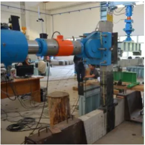
The specimens were loaded by lateral load as shown in Fig.5. The precast column was placed on the floor slab longitudinally with the result that the precast beam in the standing position. The column part was fixed by steel plate support anchored on the concrete slab floor of the laboratory. Strain gauges were patched on the concrete and on the CFRP sheet surface to measure the strain occurred during loading. The strain gauges were parched on the four location along the main CFRP sheet as shown above in Fig.3 to measure the strain distribution. The deformations of the specimens were measured using LVDTs attached on the some point of the specimens as shown in Fig.5. The load was applied gradually with rate of 0.2 kN per second to create a negative moment on the beam-column joint. All the measured data was recorded by a data logger for further analysis. Fig.6 shows the photograph of the setup specimen.
Column
Concrete Strong Floor
C
o
n
c
re
te
S
tr
o
n
g
W
a
ll
Z=1000
LVDT
LVDT
LVDT
1/3Z
1/3Z
1/3Z
Load Cell
Load Cell (Control)
[image:3.595.60.262.281.425.2]Hydraulic Jack
Fig. 5 Loading Setup of the Specimens
Fig.6 Photograph of Setup Specimen
III. RESULTS AND DISCUSSIONS
A. Flexural Response
The flexural response of the specimens due to applied load is presented in Fig.7. Generally, the increasing of load was followed by the deformation on the beam which was indicated by the increasing of the deflection . At initial stage, the curve shows a linear relationship until approximately 10 kN of applied load. The linear response of the beam-column connection may due to the linear response of CFRP sheet.
On further loading, the stiffness of the specimens PL and
PLB started to decrease. On the specimen PL, this may be caused by starting of the debonding, whereas on the specimen PLB may be caused by the prematurely initiation of the fibers rupture on the outermost fiber of main CFRP sheet. It has been reported that the prematurely fiber rupture of the fibers on specimen PL may be caused by the edge-cutting effect by the vertical U-wrap belt [9]. As the results, the stiffness of the flexural response decreased. The final failure of the specimens PL was approximately 20 kN, while the final failure of the specimen PLB was only approximately 15 kN. This indicated that the U-wrap belt was not effective to increase the flexural action on the connection system. However, the flexural response of the specimens with diagonal U-wrap belt (PLDB) was still increase linearly up to 30 kN. The decreasing of the flexural stiffness on the specimen PLDB was detected occurred when the applied load reached approximately 30 kN. This is indicated that the rupture of the micro fibers at the outermost fiber have started. The final flexural response of the specimens PLDB was approximately 40 kN. Compared to the specimen with vertical U-wrap belt (specimen PLB), the ratio of the flexural capacity of the specimens with diagonal U-wrap belt was approximately 2.7. The increasing of moment capacity on specimen PLDB indicated that the diagonal U-wrap belt was effect in increasing of bonding capacity without causing prematurely rupture of CFRP fibers.
0 5 10 15 20 25 30 35 40 45
0 10 20 30 40 50 60
A
p
p
lie
d
L
o
ad
(k
N
)
Deformation of Beam (mm)
[image:3.595.320.548.394.546.2]Without Belt (PL) With Belt (PLB) Diagonal Belt (PLDB)
Fig.7. Flexural Response
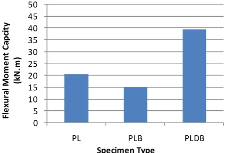
B. Moment Capacity
The moment capacity of the loaded specimens is presented in Fig.8. As it can be observed that the specimen without U-wrap belt (PL) had higher moment capacity than the specimens with vertical U-wrap (PLB). This indicated that the vertical U-wrap in the proposed connection system did not work effectively in increasing the bonding interaction of the main CFRP sheet. In the case of the CFRP sheet sustaining a non-uniform tensile load as on the precast beam-column connection system, the existence of the vertical U-wrap belt may cause prematurely cutting off of the outermost microfibers gradually inside the depth of the beams. As the results the flexural moment capacity decreased.
It has been reported that the flexural stress of the CFRP sheet due to flexural loading on the proposed system was non-uniform along the height of the main CFRP sheet [9].
B
e
a
m
Column
[image:3.595.101.247.463.609.2]Fig.9 shows the model of flexural moment capacity of the proposed precast beam-column joint using FRP sheet with shear key. Due to the hinge action on the shear key touching point, the maximum stress was on the top of beam while the stress was approximately zero on the bottom. The flexural moment capacity of the connection system may be estimated using Eq.(1) and Eq.(2) [9]. The equations was derived simply based on the couple moment of the tension force acting on the FRP sheet and compression force acting on the hinge. The moment capacity was developed under assumption of the existence of the hinge action on the edge point of the shear key where the beam sitting, as illustrated above in Fig.4. The compression force (C) worked on the hinge while the tension forces (T) was sustained by the CFRP sheet. The hinge action method was developed because of the natural matter of the CFRP sheet that not effective in sustaining a compression load. As shown in Fig.9, the critical stress is on the outermost fiber of CFRP sheet (in this case is on the top). The strain and stress then linearly decrease up to zero on the hinge point. By assuming that the fibers achieve its rupture strength, the estimated ultimate flexural capacity Mu of the joint system may be calculated by Eq.(2).
0 5 10 15 20 25 30 35 40 45 50
PL PLB PLDB
Fl
e
xur
al
M
om
e
nt
C
apc
it
y
(k
N
.m
)
[image:4.595.50.282.354.510.2]Specimen Type Fig.8 Flexural Moment Capacity
cf
h
=
2
0
0
m
m
Mu
C
o
lu
m
n
Beam
Tcf
C z
fcf
CFR P S
heet
Hinge
Fig 9. Model of Flexural Capacity
……… (1)
…….……….. (2)
Table III shows the ultimate capacity of the specimens based on the experimental results. The ultimate moment of the specimen without belt was also included for comparison.
Using the proposed equation, the estimated moment capacity indicated over estimate for both specimens PL and PLB types. This is based on the fact that the specimen PL failed under delaminating (not based on the rupture of fibers). Whereas the specimen PLB, the prematurely rupture of the outermost fiber due to cut-edge action by the vertical U-wrap belt. On the specimens with diagonal U-wrap belt indicated that the experimental moment capacity is higher than the estimated value. The higher value on the experimental compared to the estimated value indicated that the proposed equation is still under estimate.
Fig.10 illustrate the cut-edge stress occurred on the U-wrap belt. When the non-uniform tensile stress working on the longitudinal fibers (in this case, the stress distributed linearly from maximum on top and zero on bottom), then due to the existence of the U-wrap belt, the outermost fibers may experience cut-edge action. For the vertical U-wrap, the cut-edge force (Te) is equal to the tensile force on the outermost fibers (T). On the inclined U-wrap with <90, the Te is smaller than the T. Therefore the inclined U-wrap with a<90 has higher tensile force (T) for the occurrence of the cut-edge action. In opposite, on the U-wrap with >90, the Te is higher than T. Therefore the inclined U-wrap with >90 has lower tensile force (T) for the occurrence of the cut-edge action. This means that the inclined U-wrap with <90 should be applied on the precast beam-column joint using CFRP sheet in order to increase the bonding capacity.
TABLEIII
ESTIMATED FLEXURAL MOMENT CAPACITY
No Specimen
Type
Exp. Moment Capacity (kN.m)
Estimated Moment Capacity (kN.m)*
Ratio (Exp./Estimated
)
1 PL Type 20.5 26.29 0.78
2 PLB Type 15.0 26.29 0.57
3 PLDB Type 39.4 26.29 1.50
*) Estimated based on the rupture of fiber
U
-w
ra
p
B
e
lt
T
U-w
rap
Belt
T
T Te=( <90) ( <90)
T
( >90)
U-w ra
p B elt
T
eT <Te
T >Te
T
eFig.10 Illustration of cut-edge force (Te)
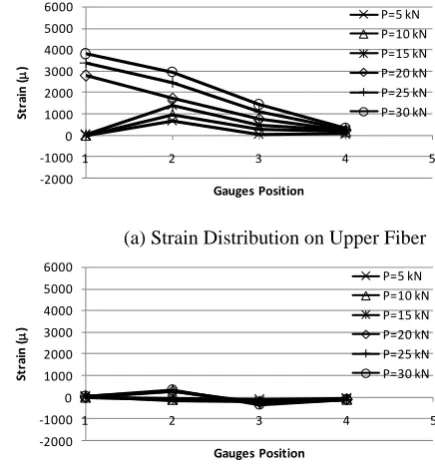
C. Strain Distribution on CFRP sheet
CFRP sheets at four points both on the upper and lower fiber, respectively, is presented in Fig.12 to Fig.14.
B
e
a
m
Column
P
U
p
p
e
r
L
o
w
e
r
[image:5.595.319.537.55.290.2]1 2 3 4
Fig.11 Notation of the Strain Gauges Positions
-2,000 -1,000 0 1,000 2,000 3,000 4,000 5,000 6,000
1 2 3 4 5
St
ra
in
(
m
)
Gauges Position
P=5 kN
P-10 kN
P=15 kN
(a) Strain Distribution on Upper Fiber
-2,000 -1,000 0 1,000 2,000 3,000 4,000 5,000 6,000
1 2 3 4 5
St
ra
in
(
m
)
Gauges Position
P=5 kN
P=10 kN
P=15 kN
(b) Strain Distribution on Lower Fiber Fig. 12 Strain Distribution on Type PL
-2000 -1000 0 1000 2000 3000 4000 5000 6000
1 2 3 4 5
St
ra
in
(
m
)
Gauges Position
P=5 kN
P=10 kN
P=15 kN
(a) Strain Distribution on Upper Fiber
-2000 -1000 0 1000 2000 3000 4000 5000 6000
1 2 3 4 5
St
ra
in
(
m
)
Gauges Position
P=5 kN
P=10 kN
P=15 kN
(b) Strain Distribution on Lower Fiber Fig.13 Strain Distribution on Type PLB
-2000 -1000 0 1000 2000 3000 4000 5000 6000
1 2 3 4 5
St
ra
in
(
m
)
Gauges Position
P=5 kN P=10 kN P=15 kN P=20 kN P=25 kN P=30 kN
(a) Strain Distribution on Upper Fiber
-2000 -1000 0 1000 2000 3000 4000 5000 6000
1 2 3 4 5
St
ra
in
(
m
)
Gauges Position
P=5 kN P=10 kN P=15 kN P=20 kN P=25 kN P=30 kN
(b) Strain Distribution on Lower Fiber Fig.14 Strain Distribution on Type PLDB
Generally, results indicated that the higher strain occurred on the upper fibers which was distributed from maximum on the point 1 (on column side) and minimum on the CFRP sheet end on the beam side (point 4). Whereas stress distribution on the lower fiber indicated that the strain was relatively small along the gauges position. This indicated that the assumption taken on developing of the moment capacity model has a good agreement to the experimental fact. The moment capacity was developed under assumption of the existence of the hinge action on the edge point of the shear key where the precast beam sitting. The compression force (C) worked on the hinge while the tension forces (T) was sustained by the CFRP sheet. Therefore the stress on the lower part of CFRP sheet was assumed to be zero.
D. Failure Mode
[image:5.595.57.290.64.753.2]failed. On the specimens PLDB with diagonal U-wrap belts, was also failed under the same manner with the specimen PLB. However, the failure load was much higher than the PLB specimens. This indicated that the prematurely cut-off of the outermost fibers could be avoid by applying U-wrap belt diagonally. Failure specimen with diagonal U-wrap belt is shown in Fig.15(c). As it can be observed that about 1/3 of CFRP sheet width failed due to fiber rupture.
(a) Type PL (b) Type PLB
(c) Type PLDB
Fig. 15 Failure Mode of Specimens
IV. CONCLUSION
The discussion of the experimental results provided the following conclusions:
(1) Prematurely cutting off of the outermost fibers may occur in the case of the CFRP sheet sustaining a non-uniform tensile stress as on the precast beam-column connection system.
(2) The applying of the diagonal U-wrap belt on the non-uniform distributed tensile stress may avoid the prematurely cut-off of the fibers.
(3) The connection of the precast beam-column using CFRP sheet with diagonal U-wrap belt has higher flexural moment capacity than the connection with vertical U-wrap belt. (4) Experimental fact indicated that the proposed connection system using CFRP sheet with shear key may be achieved by the model of hinge action on the contact point between precast beam and precast column on the shear key.
ACKNOWLEDGMENT
The author gratefully acknowledges to PT. Fyfe Fibrwrap Indonesia in supporting of fiber materials. The technical support and assistance of the students in performing the experimental test is also highly appreciated. The author would like to extend the special thanks to the staffs of the Laboratory of Structural and Material of Hasanuddin University for their invaluable assistance.
REFERENCES
[1] L.F.Maya and L.Albajar. (2012), “Beam-Column Connection for
Precast Concrete Frames Using High Performance Fiber Reinforced Cement Composites”, HPFRCC 6, 347-354
[2] Rohit B. Nimse, Digesh D.Joshi and Paresh V.Patel. (2014),
“Behavior of wet precast beam column connections under progressive collapse scenario: an experimental study”, Int J Adv Struct Eng, 6, 149–159
[3] Brooke,N., Ingham,J.(2006), “Advanced fiber reinforced precast
concrete beam-column joint”, Proceeding of New Zealand Concrete Industry Conference, New Zealand.
[4] G. Metelli1 And P. Riva, (2008). “Behaviour Of A Beam To Column
“Dry” Joint For Precast Concrete Elements”, The 14th World Conference On Earthquake Engineering, Beijing, China
[5] R. Vidjeapriyal and K.P. Jaya. (2012), “Behaviour Of Precast
Beam-Column Tie-Rod Connection Under Cyclic Load”, ISET Golden Jubilee Symposium, D016
[6] Sergio M Alcocer, Rene Carranza, and David Perez-Navarrete,. (2000),
“Behaviour Of a Precast Concrete Beam-Column Connection”, 12WCEE2000, 1543-1541.
[7] Ali R.Khaloo and H.Parastesh. (2003), “Cyclic Loading of Ductile
Precast Concrete Beam-Column Connection”, ACI Structural Journal, 100 (3), 291-296.
[8] Tarek K., Hasasan and Sami H.Rizakalla, (2004), Bond Mechanism of
Near-Surface-Mounted Fiber-Reinforced Polymer Bars for Flexural Strengthening of Concrete Structures, ACI Structural Journal, 101 (6), 830-839
[9] R.Djamaluddin, R.Irmawaty and H.Rante, (2016), Flexural Capacity
Of the Precast RC Beam-Column Connection Using CFRP Sheet, The Proceeding of the Civil Engineering Conference In The Asian Region Cecar 7, Hawaii | August 30 - September 2, 2016.
[10] Indonesian Nasional Standard (SNI) (2002). “Tata Cara Perhitungan
Struktur Beton untuk Bangunan Gedung”, SNI 03-2847-2002
[11] ACI, Committee 440.2R-08. (2008). Guide for the Design and
Construction of Externally Bonded FRP Systems for Strengthening Concrete Structure. U.S.A: American Concreate Institute.
[12] J.K. Wight (2011). “Reinforced Concrete Mechanics and Design” 6th