Abstract—The aim of this study was to investigate the effect of the operating temperature on the performance of a Fe/Al2O3 catalyst with low Fe loading during Fischer-Tropsch reaction. The catalyst was prepared by incipient wetness impregnation method and evaluated at 250 – 300 oC. The experimental results show that both selectivity and catalyst activity are strongly affected by the operating temperature. Increasing the temperature leads to increased catalytic activity and shifts the selectivity of products towards lighter hydrocarbons. While a clear dependence of the olefin-to-paraffin ratio (O/P) for C4 and C5 hydrocarbons on the operating temperature was not obtained, the O/P for C2 and C3 hydrocarbons was found to decrease with an increasing temperature.
Keywords—Fe/Al2O3 catalyst, Fischer-Tropsch, Reaction temperature.
I. INTRODUCTION
ICHER-TROPSCH (FT) processes convert synthesis gas (or syngas) into a wide-ranging mixture of hydrocarbons, predominantly consisting of n-paraffins and α-olefins. In smaller quantities, molecules of branched paraffins and oxygenates such as alcohols, aldehydes and carbon acids are also present in the product stream. Developed by German researchers Franz Fischer and Hans Tropsch in the 1920’s at the Kaiser Wilhelm Institute [1, 2], FT synthesis has remained a vital aspect in the energy sector for decades. It plays an essential role as a promising environmentally friendly process for the production of transportation fuels, chemicals and waxes. Since the mid-1950’s, coal-based FT synthesis has been successfully practiced on a commercial scale by Sasol, a renowned integrated energy and chemical company based in South Africa. In its early years, Sasol used circulating fluidized-bed reactors (CFBRs) and tubular fixed-bed reactors (TFBRs) packed with promoted iron as the catalyst for its operations [2]. FT synthesis has since then evolved into a
This work was supported in part by the National Research Foundation (NRF) (90737) and the University of Johannesburg (05-15-265590).
G. Muala is with the Department of Chemical Engineering, University of Johannesburg (e-mail: [email protected]).
A. Iloy is with the Department of Chemical Engineering, University of Johannesburg (e-mail: [email protected]).
K. Jalama is with the Department of Chemical Engineering, University of Johannesburg (corresponding author: +27(0)11-559-6157; e-mail: kjalama@ uj.ac.za).
broadly industrialized technology that is applied by other companies around the world such as BP, Shell, Chevron and Exxon-Mobil [3].
Syngas, the feedstock for FT processes can be derived from natural gas, coal, biomass or heavy oil streams [4, 5]. The desired FT product slate determines the choice of the synthesis reactor, catalyst and the operating conditions, all of which subsequently determine the required composition and characteristics of the syngas [6].
Transition metals such cobalt, iron and ruthenium are used to catalyze the FT process. Both iron and cobalt are presently commonly commercially used at operation temperatures of 200-300 °C and pressures of 10-60 bar [7]. In comparison to cobalt catalysts, iron catalysts are more suitable to use with coal derived syngas as it is much more challenging to prevent catalyst poisons derived from the coal with cobalt catalyst [8]. Most iron-based catalysts that are used for commercial applications and in many scientific studies possess a high loading of Fe. Reports on catalytic properties for low-loaded Fe-based catalysts are limited in literature. It is expected that different levels of interactions of Fe and the support exist in high-loaded and low-loaded Fe catalysts and may lead to changes in catalytic performance for FT reaction. Hence, the aim of this study is to investigate the effect of operating temperature on FT reaction over a low-loaded Fe catalyst (10%Fe/Al2O3).
II. EXPERIMENTALDETAILS
A. Catalyst Preparation
Alumina powder was first mixed with distilled water at a 1:1 mass ratio and air-dried for 24 hours at 120 °C. It was then calcined in flowing air 500 °C for 24 hours. Following calcination, the support was crushed and impregnated with an aqueous solution of iron (III) nitrate with the aim to produce a 10%Fe/Al2O3 catalyst. The impregnated support was subsequently dried at 120 °C for 24 hours before calcination in air at 500 °C for 24 hours.
B. Catalyst Characterization
The prepared catalyst was characterized using temperature programmed reduction (TPR) in order to determine the appropriate activation temperature before FT reaction. The
Fischer-Tropsch Synthesis over Fe/Al
2
O
3
Catalyst with Low Fe Loading:
Effect of Reaction Temperature
Guida Muala, R. A. Iloy, Kalala Jalama
analysis was performed in a glass reactor connected to a thermal conductivity detector (TCD). 100 mg of the catalyst sample were first loaded in the reactor and heated (10 oC/min), under a flow of N2 (30 ml/min) form room temperature to 150 o
C were it was held for 30 min in order to remove volatile contaminants. After cooling below 60 oC, the analysis gas (5% H2 in Ar) was introduced and the TCD signal was monitored until a stable baseline was reached before ramping (10 o
C/min) the temperature to 600 oC to complete the analysis.
C. Catalyst evaluation
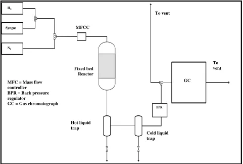
The schematic drawing for catalyst testing setup is shown in figure 1.
The reactor had an inlet gas supply line which was connected to three supply lines that could be switched through the use of valves. The three separate supplies were of syngas (H2:CO = 2:1), N2 and H2. Nitrogen was used for reactor pressure testing in order to check for leaks.
Before the FT reaction, 500 mg of catalyst were first activated at atmospheric pressure using pure hydrogen (30 ml/min) at 300 oC for 6 hours then at 330 for 2 hours. The activated catalyst was subsequently cooled under the flow of H2 to 100 oC where the synthesis gas (10%N2, 30% CO with H2 balance) was introduced in the reactor and the pressure increased to 20 bar using of a mass flow controller upstream
of the reactor and a back pressure regulator located at the reactor exit. When the operating pressure was reached, the operating feed flowrate was set at 10 ml/min. The reaction was performed at various temperatures, i.e. 250 to 300 oC.
The analysis of the reactor exit gas was performed on-line using a Dani Master gas chromatograph (GC) equipped with a flame ionization detector (FID) and a TCD which were connected to a Supel-Q Plot fused silica capillary column 30m x 0.32 mm and a 60/80 Carboxen 1000 column, respectively. C1-C9 compounds were detected on FID, while H2, CO2, CO, CH4 gas and N2 were detected on TCD.
III. RESULTSANDDISCUSSION
A. Catalyst Characterization
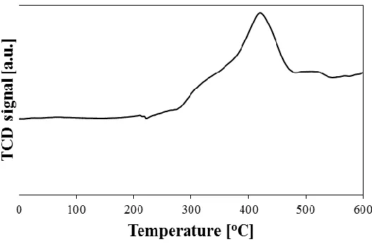
The profile for the 10%Fe/Al2O3 is presented in figure 2. The data show that significant reduction starts at ca. 275 oC where a peak started and was followed by another peak that started around 360 oC and which reached a maximum value at ca. 425 oC. These peaks that extend over a wide range of temperature suggest the reduction of iron oxide species with various types of interaction with the Al2O3 support. Based on these data, temperatures of 300 and 330 oC were selected for catalyst activation prior to the FT reaction.
[image:2.612.46.527.390.714.2]P-27
Fig. 1. Schematic diagram of catalyst evaluation setup. H2 Hot liquid trap To vent To vent GC Fixed bed Reactor MFCC Syngas N2 BPR Cold liquid trap MFC = Mass flow
controller
BPR = Back pressure regulator
GC = Gas chromatograph
Fig. 2. TPR profile for calcined 10 wt% Fe/Al2O3 catalyst
B. Catalyst evaluation
Effect of temperature on CO conversion rate (-rCO) and CO2 formation rate (rCO2). The effect of temperature
on iron-catalysed FT synthesis has been reported in numerous fundamental FT studies [1, 9 - 12]. The consensus is that as the temperature is increased, the CO conversion rates increase. The data shown in figure 3 are in agreements with the literature as –rCO increases with an increasing temperature from 250 to 300 oC. The rates of CO conversion showed close to a linear increase with the rise in temperature. In FT synthesis, the dissociation of the C-O bond and the subsequent reaction with H2 represents the commencement of the FT reaction mechanism. Higher operating temperatures instigate and promote the rate of these two steps [13]. This results in an increase in activity as the operating temperature is increased and explains the resulting observation.
The CO2 formation rate and selectivity also showed a similar trend with a rise in temperature as presented in figures 4 and 5, respectively. CO2 was not present in the feed stream, and thus can only be a product of the WGS reaction.
The slight increase in WGS activity with the rise in temperature can be due to kinetic effects [14]. However, literature suggests that at temperatures of 250 °C and above, the WGS reaction may reach equilibrium on iron catalysts [2, 15]. This may explain the sluggish increase in the CO2 production in our temperature range.
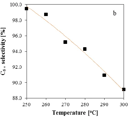
Effect of temperature on product selectivity. Experimental results in Figures 6 and 7 respectively show that the methane selectivity rises strongly while the selectivity for C5+ hydrocarbons decreases with an increase in temperature. These findings have remained consistent throughout decades of numerous studies that have shown that regardless of the type of catalyst and feed gas composition, an increase in temperature results in a rise in methane selectivity [2, 16 –
23]. In another standpoint, a rise in methane selectivity with increasing temperature is reflective of the decrease in the probability of chain growth and thus a shift to lighter molecular mass compounds results. The methanation reaction is highly governed by the rate of H2 adsorption on the catalyst. Another aspect to consider is the dissociation of the C-O bond. This process is essential in providing the active carbon atoms that will bond with the available H2 molecules [16- 21]. Studies have shown some controversy on the analysis of the effect of temperature on the O/P ratio with chain propagation or increasing molecular weight. Some authors reported increasing behaviour [2, 24 - 29], others reported the opposite [30]. Our experimental results also showed mixed results for the O/P ratio with temperature for C2 to C5 hydrocarbons.
Figures 8 a and b show that the C2 and C3 O/P ratio decreases with an increase in temperature. Another observation is that the O/P ratio decreases rapidly between temperatures of 250 and 270°C and slowly above 280°C. A decrease in the O/P ratio can be caused by higher activation energy of chain hydrogenation, n-paraffin formation, compared to the desorption of 1-olefin.
Fig. 3. CO conversion rate against temperature. H2/CO = 1.8; P=20 bar.
Fig. 4. CO2 conversion vs. temperature. H2/CO = 1.8; P=20 bar
[image:4.612.162.470.378.561.2]Fig. 5. CO2 selectivity vs. temperature, H2/CO = 1.8; P=20 bar.
Fig. 6. Methane selectivity vs. temperature. H2/CO = 1.8; P=20 bar
[image:5.612.201.421.470.665.2]
Fig. 8. Olefin to paraffin ratio for a) C2, b) C3, c) C4 and d) C5.
IV. CONCLUSION
This work has shown that the activity of a 10%Fe/Al2O3 catalyst and the selectivity of products during an FT reaction are strongly dependent on the temperature. Increasing the temperature leads to increased catalytic activity, subsequently resulting in higher FT conversions. However, the product distribution is adversely affected by high temperatures which shift the selectivity towards lighter hydrocarbons.
The O/P ratio for C2 - C3 decreased with increasing temperatures.
REFERENCES
[1] Dry, M. E. (1989) Commercial conversion of carbon monoxide to fuels and chemicals. Journal of Organometallic Chemistry, pp. 117-127.
[2] Dry, M. E., Anderson, J. R., & Boudart, M. (1981), The Fischer-Tropsch Synthesis. In Catalysis- Science and Technology; New York: Springer-Verlag, pp. 160-255.
[3] Steynberg, A., et al. (2004) Synthesis gas production for FT synthesis. Studies in surface science and catalysis, pp. 258-405.
[4] Riedel, T., & Schaub, G. (2003) Low temperature Fischer Tropsch synthesis on cobalt catalysts effects of CO2. Topics in Catalysis, vol. 26, pp. 145.
[5] Jager, B., & Espinoza, R. (1995) Advances in low-temperature Fischer-Tropsch synthesis. Catalysis Today, vol.23, pp. 17–28.
[6] Sie, S.T. (1998) Process development and scale up: IV Case history of the development of a Fischer-Tropsch synthesis process, Review Chemical Engineering, vol. 14, pp. 109–157.
[7] Steynberg, A., et al. (2004) Fischer-Tropsch Reactors. Studies in surface science and catalysis, vol. 152, pp. 64-195.
[8] Dry, M. E. (2007) The Fischer-Tropsch process: 1950-2000. Catalysis Today, vol. 71, pp. 227.
[9] Musanda, T. (1999) PhD thesis, Graphical methods for the representation of the Fischer-Tropsch reaction: Towards Understanding the mixed Iron-Cobalt catalyst systems, Johannesburg.
[10] Chronis, T. (1999) PhD thesis, A Fischer-Tropsch study of Co/Ru Catalysts, Johannesburg.
[11] Dixit, R. S. & Taviarides, L.L. (1983) Industrial & Engineering Chemistry Process Design and Development, vol.22, pp. 1-9.
[12] Hurlbut, R. S., Puskas, I. & Schumacher, D. J. (1996) Energy and Fuels, vol.10, pp. 537.
[13] Vannice, M. A. (1977) Journal of Catalysis., vol. 50, pp.228.
[14] Dragomir, B., Branislav, T. & Nimir, E. (2015) Chemical Role of water-gas-shift reaction in Fischer–Tropsch synthesis on iron catalysts: A review, Catalysis Today, Qatar
[15] Zimmerman, W.H. & Bukur, D.B. (1990) Reaction kinetics over iron catalysts used for the Fischer Tropsch synthesis, The Canadian Journal of Chemical Engineering. vol.68, pp. 292–301.
[16] Alstrup, I. (1995) Journal of Catalysis, vol. 151, pp. 216-225.
[17] Anderson, R. B. (1953) Advances in Catalysis., vol. 5, Frankenburg, Komarewsky, Rideal, New York: Academic Press Inc.
[18] Sa, V.H. & Harriott, P. (1980) Journal of Catalysis., vol. 64, pp. 272-283.
[19] Van Herwijnen, T., Van Doesburg, H. & De Jong, W. A. (1973) Journal. of Catalysis., vol. 28, p.391-402.
[20] Gall, D., Gibson, E. J. & Hall, C. C. (1952) Journal of Applied Chemistry, vol. 2 London, pp.371.
[21] Hall, C. C., Gall, D. & Smith, S. L. (1952) Journal of Institute of Petroleum., vol. 38, pp.845.
[22] Anderson, R.B. (1956) Catalysts for the Fischer-Tropsch synthesis, vol. 4, Van Nostrand Reinhold, New York.
[23] Schulz, H., Van Steen, E. & Claeys, M. (1993) Olefin formation, hydrogenation and isomerization in the kinetic regime of Fischer-Tropsch synthesis, in Selective hydrogenation and dehydrogenation, DGMK, Kassel, Germany.
[24] Donnelly, T. J. & Satterfield, C. N. (1989) Product distributions of the Fischer-Tropsch synthesis on precipitated iron catalysts, Applied Catalysis. vol. 52, pp. 93–114.
[25] Glebov, L. S. & Kliger, G. A. (1994) The molecular weight distribution of the products of the Fischer-Tropsch synthesis, Russian Chemical Reviews. vol. 63, pp. 185–194.
[26] Bukur, D.B. & Brown, R.F. (1987) The Canadian Journal of Chemical Engineering., vol. 65, pp.604.
[27] De Guegd, R. M. (2004) PhD thesis, Fischer-Tropsch Synthesis Revisited; Efficiency and Selectivity Benefits from Imposing Temporal and/or Spatial Structure in the Reactor. Netherlands
[28] Huff, G.A. &Satterfield, C.N. (1984) Some kinetic design considerations in the Fischer-Tropsch synthesis on a reduced fused-magnetite catalyst Industrial & Engineering Chemistry Process Design and Development., vol. 23, pp.696 - 854.
[29] Madon, R.J., Iglesia, E., & Reyes, S.C. (1993) Non-flory product distributions in Fischer–Tropsch synthesis catalyzed by ruthenium, cobalt, and iron, in: S.L. Suib, and M.E. Davis (eds.), Selectivity in Catalysis, ACS Symposium Series, American Chemical Society, pp. 382–396.
[30] Espinoza, R.L., Steynberg, A.P., Jager, B., & Vosloo, A.C. (1999) Applied Catalysis A: General, v.186, pp.13-26.