Abstract—This paper presents a shape design methodology to model and improve the geometry of a generic special shaped milling cutter. A dedicated customized tool design modeler is developed to verify the geometry of the cutter. This modeler helps in rendering the proposed three-dimensional parametric definition of the cutter in any CAD modeling environment by suitable translation. The modeled tool is analyzed using finite element analysis to study the cutting insert and the cutter body under transient dynamic load conditions while varying the rake angle of the insert and insert seat. The cutter is redesigned, based on the feedbacks obtained while performing the analysis for the optimum rake angle of the insert. Two different types of special shaped cutters are generated and shown here, from the same definition, to illustrate the generic definition of the special milling cutters.
Index Terms—finite element analysis, optimum geometry, special shaped milling cutter, surface modeling
I. INTRODUCTION
ETAL removal through cutting is still important for many manufacturing industries, and the geometry and dimensional accuracy of the cutting tool along with the quality of its cutting surface directly influence the precision and quality of the machined products. To precisely simulate any machining operation, accurate models of cutting tools used in the machining processes are required. The demand for high-precision, high-performance cutting tools is always on rise, specifically with the rise in the complexity of the products manufactured. Special cutting tools are used not only to machine complex surfaces but also for mass manufacturing. Replacing a number of tools with just one results in savings in many aspects. It also improves the product’s quality, saves time, reduces cost, etc. Designing a special tool includes many aspects. To obtain the optimum geometry of a special tool, modeling and analysis of the cutting profiles of the tool based on cutting forces during machining plays an important role.
In most of the cases, the geometry of cutting tools are developed in a manner that it is tough to define a unified
Manuscript received March 23, 2013; revised April 11, 2013. This work was supported in part by the Science and Engineering Research Council (SERC) of the Department of Science and Technology (DST) New Delhi, India under Grant SR/S3/MERC-0038/2008.
Mohammed Rajik Khan is with the National Institute of Technology, Rourkela, 769008, India (phone: +91-661-2462853; e-mail: khanmr@ nitrkl.ac.in).
Puneet Tandon is with PDPM-Indian Institute of Information Technology, Design & Manufacturing Jabalpur, 482005, India. (e-mail: [email protected]).
representation scheme for the family of the cutter [1]-[2]. Some work has been done by the authors [3]-[4] that helps define the geometry of a cutting tool in terms of biparametric surface patches. Using a similar approach, one may develop comprehensive three-dimensional (3D) surface based definitions of the special shaped milling cutters. These 3D definitions can be used to optimize the design of the cutter based on the finite element based engineering analysis [5]-[8]. The generic definition of the cutter developed can also be used to design a cutter for similar / related application(s), simulation of cutting process, and fabricating the cutting tool.
Although considerable work has been done by the researchers to study the conventional single point and multi-point cutting tools [1], [3]-[4] but very few special cutting tools have attracted the research fraternity in spite of the fact that they are good candidates for generating complex surfaces. The reasons for this could be varieties in the designs of customized cutters and their geometric complexity. In fact, Kuo and Wu [2] have proposed a methodology for geometric solution of the roller nest mill cutter. Hsieh and Tsai [9] have discussed the geometric modeling and grinder design for toroid-cone shaped cutters. Radzevich [10] has suggested a novel method for mathematical modeling of an optimized form-cutting tool for machining a given sculptured surface. The work in the direction of development of geometry design of a form milling cutter for precisely obtaining the complex freeform surfaces is done by Wang et al. [11]. Also, Radzevich [12] and Hsieh et al. [13] have worked a lot in the area of designing and modeling the precision gear hobs. If proper 3D geometric definitions of special cutting tools are available then it will be of immense benefit to the manufacturing world due to possibilities in obtaining a better design of the cutter as well as ease in simulation of a machining process before actual machining.
This paper aims to develop an optimum geometric model of a special shaped milling cutter based on the application. The evolution of the present work is based on the authors’ previous work [3] on surface modeling of a generic flat end mill. To overcome the difficulties associated with modeling a complex cutter, an interface in the form of a customized tool design modeler is developed. This design tool can render the three-dimensional geometry of the cutter in any commercial CAD environment for validation and design improvements. In this work, the proposed 3D model of the special shaped milling cutter is used for finite element analysis to optimize its design. The results of stress distribution, strain intensity and deformation are presented
Development of the Geometry and its
Redesigning for a Special Shaped Milling Cutter
Mohammed Rajik Khan, and Puneet Tandon, Member, IAENG
for the insert and the body of the cutter under transient dynamic load conditions for different tool rake angles. Based on the minimum stresses developed for a particular rake angle of the insert (and insert seat), the cutter’s design is modified and its geometry optimized.
Section II of the manuscript describes in brief the design of various geometric features of the circular form milling cutter. Section III discusses the design implementation of the proposed methodology and its validation. Section IV presents the design improvements and redesigning of the special shaped milling cutters designed for two different applications (a) leather cutting industries and (b) metal cutting industries based on the finite element analysis. Finally, concluding remarks and results are discussed in Section V.
II. GEOMETRIC DESIGN OF THE CUTTER
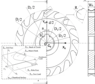
A special shaped milling cutter is a peripheral cutter whose cutting edges are shaped so as to generate a special profile on the surfaces machined. This special cutter can be used to machine various hard and soft metals, leathers, woods, etc. to reproduce the desired surface profile. There exists a variety of special milling cutters. In this work, we have taken two specific applications of such a cutter for the illustration of the paradigm. The proposed definition of the special shaped milling cutter is generic in nature. Further, from this work, various tools in the family of customized form milling cutters can be generated. In the case of an insert type cutter, the cutting teeth of the solid type cutter are replaced with the inserts. Here, the body of the cutter is made of one piece of material and the insert teeth of a different material. All the inserts of the cutter are similar in geometry. In this work, a unified insert tooth is modeled in detail. Later, this insert is placed in the proper position and orientation on the periphery of the cutter body as many times as the number of teeth of the cutter. The geometry of the special cutter projected on a two-dimensional orthographic plane is shown in Fig. 1. D1, D2, d, Dr, and Di are diameter of hub1, diameter of hub2, bore diameter, root circle diameter of the insert seat, and outer circle diameter of insert seat respectively. R is the radius of fillet and W and Wb is the width of the insert seat / insert and cutter body respectively. The keyway in the hub1 is specified in terms of a and b, as the width and depth of the keyway respectively. For the convenience of modeling, the geometric design of the special milling cutter can be
considered to be made up of two segments i.e. Insert body and Cutter body.
A. Modeling of a Unified Insert Tooth
The geometric model of an unified insert tooth is designed to consist of eight functional surfaces and one chamfered surface. These surface patches are labeled as
1
to8and 8,1(chamfered surface) respectively and shown with the help of Fig. 1. The insert is placed in a local right-hand Cartesian frame of referenceC2{O2:X2,Y2,Z2} with
X2-axis along the rake face, Y2-axis along the end face and Z2-axis along the intersection of these two surfaces. All the above surface patches except the surface patch4are planar surfaces and are defined by transforming suitable unbounded two-dimensional planes with their origins initially coinciding with the origin inC2to their final
orientation. Surface 4is developed by linearly sweeping a
curve, modeled as a non-uniform rational B-spline (NURBS) and called NURBS sweep surface here.
The rotational angle γ2 is the angle through which the Z2X2 plane is rotated about Z2 axis in the clockwise direction, followed by translation by an amount l1cos2l2
along X2 axis to form the peripheral land (2&3). Here, l1
and l2 are the lengths of the peripheral land and back of tooth of the insert respectively.
The major flank (4) is formed by sweeping a NURBS
curve V2V4 lying on rake face (1) along the peripheral land
)
(2 in the direction V1V7. Here, V2 and V4 are the
vertices of the major cutting edge of the insert. Vertex V1 is the intersection point of surface patches 1,2and 5 and
vertex V7 is the intersection point of surface patches 7
5 2, &
. The major cutting edge V2V4 is developed using a
NURBS faired curve approach.
In the NURBS faired curve approach, the input data points act as control points and the curve approximates the control points. Such NURBS curves are known to represent the freeform objects closely. This method has excellent model coverage and a high degree of freedom to develop the major cutting edge of the insert. A instantaneous point p(t) in a parametric domain is represented by NURBS [14] as follows,
), ( )
(t BR, t
p ik
n
o i
i
where
,) (
0 , , ,
t N h
t N h t
R n
i k i i
k i i k i
for 0t2.
Here, Bi are the position vectors of the n vertices of the control polygon, t is the parameter, Ri,k(t) is the rational basis function of the NURBS curve, Ni,k(t) is the normalized basis function of the NURBS curve, k is the order of the NURBS curve and hi is the weight corresponding to Bi. In this manuscript, the NURBS curve is plotted with k = 4 and n = 4 and is mathematically defined as p4(t,s)
p(t).Ts , where the transformation matrix
1 0 sin cos
0 1 0 0
0 0 1 0
0 0 0 1
] [
2
2
s
s
[image:2.595.89.250.627.769.2]Ts , for 0s1.
For 0t1,
1 3 3
3 4.5 1.75
1.5
(0.25 )) 25 . 0 ( 5 . 1 75 . 1 5 . 4 3 3 3 1 ) ( 3 3 3 2 2 3 2 1 3 2 0 3 3 3 3 2 2 2 3 2 1 1 3 2 0 2 t h t t h t t t h t t t h t h B t t h B t t t h B t t t h V t p
For 1t2,
) 3 3 1 ( ) 75 . 1 6 6 2 ( ) 5 . 0 3 5 2 ( ) 25 . 0 5 . 1 3 2 ( 3 3 1 75 . 1 6 6 2 ) 5 . 0 3 5 2 ( ) 25 . 0 5 . 1 3 2 ( )( 2 3
4 3 2 3 3 2 2 3 2 1 3 2 4 4 3 2 3 3 3 2 2 2 3 2 1 1 t t t h t t t h t t t h t t t h t t t h V t t t h B t t t h B t t t h B t p
where V2,B1,B2,B3& V4 are the control points and h0h4 are the weights of the NURBS curve V2V4.
B. Modeling of the Cutter Body
Fig. 1 shows the schematic two-dimensional projected orthographic view of the body of the special shaped milling cutter with its sectional view comprising of insert seat and the core cutter body. The surface patches comprising insert seat are geometrically modeled in a local coordinate systemC1, while those of core cutter body are modeled
placing them in the global coordinate systemC0. The surface
patches that make up the insert seat of the cutter are nine in number, labeled 1to9, while there are twelve surface patches that form the core cutter body (50to61) of the
cutter.
An insert seat is a cavity created in the cutter body to place the insert. The composite section curve profile, V0V6,
(in X1Y1 plane) is swept to generate the insert seat surfaces
as shown in Fig. 2. Segments V0V1V2 of the composite curve
is a circular arc of radius R with centre of the arc at vertex
1
c and corresponds to the fillet of an insert seat, while segmentsV2V3, V3V4, V4V5 and V5V6 are straight lines in
two-dimensional projective plane and correspond to the four land widths, namely end face, face, land and back of insert seat.
To model the cross-sectional profile in two-dimensional plane, the input parameters are (i) length of the face(l3), (ii)
angles obtained to form face (1i), and land (2i) about Z1
axis, (iii) radius of fillet (R), (iv) outer diameter of insert seat (Di) and root circle diameter of insert seat (DR) and (v) number of flutes (N).
As discussed earlier, the cross-sectional profile of an insert seat consists of one parametric circular arc and four parametric linear edges, labeled as, p1(s) top5(s). Curve
) (
1 s
p is a circular arc of radius R while p2(s),p3(s),p4(s)
and p5(s) are straight lines in two-dimensional space.
The surface patches that join all the insert seats and completes the body of the special milling cutter are identified as surface patches of core cutter body. They are twelve in number, labeled as50,...,61. Besides, there are two transitional (chamfered) surfaces, labeled as50,52&51,52.
III. DESIGN IMPLEMENTATION
In this work, a customized tool design modeler has been developed. This design tool helps in rendering the proposed three-dimensional model, defined with the help of parametric equations, in any CAD environment by suitable translation of the geometric data of the cutter. Developing an interface is advantageous in comparison to using the APIs of existing CAD packages, as it does not limit the convenience of the proposed modeling paradigm, primarily the conversion of free-form parametric surfaces. This also helps in validating the mathematical models, thus,
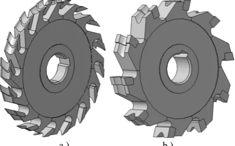
[image:3.595.48.290.157.249.2]a.) b.)
Fig. 3. Rendering of a special milling cutter designed for a.) leather industries b.) metal cutting industries
Fig. 2. Composite sectional curve.
TABLEI
GEOMETRIC PARAMETERS AND INPUT DATA FOR A SPECIAL MILLING CUTTER
Input data Cutter 1 Cutter 2
Number of inserts (N) 16 10
Dimensional Parameters Value(mm) Value(mm) Outer diameter of insert seat (Di) 92.7 92.7 Root circle diameter of insert seat (DR) 73.0 73.9 Outer diameter of hub2 (D2) 69.0 69.0 Outer diameter of hub1 (D1) 34.0 34.0
Bore diameter (d) 20.0 20.0
Fillet radius (R) 3.4 3.65
Length of peripheral land (l1) 5.5 5.5
Length of back of tooth (l2) 6.5 6.5
Length of face of insert seat (l3) 5.0 5.0 Width of the insert seat / insert (W) 10.0 16.0 Width of the cutter body (Wb) 9.0 15.0 Width’s of peripheral land 2& 3 1.0 4.0
Rotational angles Value (degrees)
Value (degrees)
2
-31 -71
i
1
-54 -14
i
2
[image:3.595.307.548.609.758.2]developed.
Based on the above proposed generic definition, the geometric parameters needed to completely describe a special milling cutter are shown in Table I. The tool design interface was developed in Microsoft Visual C++ using Dot Net 3.5 technology for Windows XP / Win 2003 operating systems. The users enter the 3D geometric parameters proposed in the work through the variable management module of the tool design modeler and the output is rendered in CATIA CAD modeling environment (as shown in Fig. 3) to validate the geometry of the special shaped milling cutter.
The users can change the geometric parameters of the cutter in the same module (variable management) tool design interface. This interface also provides the ability to model similar cutters by simply changing the values of input parameters.
IV. DESIGN IMPROVEMENT AND REDESIGNING THE CUTTER
Finite element based engineering analysis (FEA) is performed on the 3D model of the special shaped milling cutter created using the proposed methodology to optimize its design. This exercise helps in obtaining the optimum values of different angles of the cutter to obtain the best milling practice in terms of least stresses on the cutter teeth. The cutter generated in CATIA (as described in Section III) is exported for Structural Transient Dynamic Analysis in ANSYS. ANSYS is an implicit finite element (FE) program which uses the Newmark time integration method for the solution of the transient dynamic equilibrium equation. The
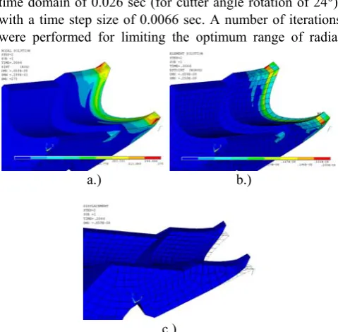
cutting insert was analyzed under transient dynamic load conditions while varying the cutter radial rake angle of the insert and insert seat. The results of nodal solutions for the contour plots of stress distribution, deformation and elemental total strain intensity are presented for the insert and its body under a variety of cutter radial rake angles. The cutter model is modified and optimized based on the feedbacks from the analysis. This is an iterative process and the result is an optimized CAD model of a special shaped milling cutter.
[image:4.595.44.283.193.259.2]A. Special Shaped Milling Cutter for Leather Industries
Fig. 3a shows one of the special shaped milling cutters designed for generating shape on objects made of leather. The cutter is re-designed as per the feedback from the finite element analysis. Material used here for the insert is cemented carbide (WC), who’s mechanical and thermal properties are given in Table II A. The insert material has a hardness of 1700HV. The cutter body is of gray cast iron with its mechanical and thermal properties mentioned in Table II A and the material used for the work piece is ecor sole leather. Its mechanical properties are shown in Table II B. The cutter is meshed using solid brick 8node45 element. This 3-D brick element is defined by eight nodes having three degrees of freedom at each node i.e. translations in the nodal X, Y and Z directions. The element also has plasticity, creep, swelling, stress stiffening, large deflection, and large strain capabilities. The meshed model shown in Fig. 4a is built as a general orthogonal cutting model. The tool is modeled with a fine mesh at the insert, with less refinement at insert seat, while the core cutter body portion is modeled coarsely. Under the cutting tests, the cutting conditions are spindle speed, N= 150 rpm, feedrate, f = 240 mm/min for
a depth of cut 6 mm and width of cut, w=10 mm. For our
simulation, load has been applied on a single insert in radial and tangential directions. The direction of load application on the cutter is shown in Fig. 4b.
The transient dynamic analysis is carried out for a total time domain of 0.026 sec (for cutter angle rotation of 24°), with a time step size of 0.0066 sec. A number of iterations were performed for limiting the optimum range of radial
TABLEII A
MECHANICAL AND THERMAL PROPERTIES OF TOOL INSERT (P20
CEMENTED CARBIDE) AND CUTTER BODY (GREY CAST IRON)
Materials Cemented Carbide Gray Cast Iron
Density (kg/m3) 12100 7710
Young’s modulus, E (GPa) 558 103
Poisson’s ratio, n 0.22 0.27
Yield stress, sy (MPa) 850 207 Thermal conductivity
(W/m°C) 46 35
TABLEII B
MECHANICAL PROPERTIES OF WORK PIECE, ECOR SOLE LEATHER SHEETS
Material Ecor Sole Leather
Density ( kg/m3) 1000
Shear modulus, E (MPa) 3
Coefficient of friction, μ 0.6
Bending stiffness, (MPa) 100
Ultimate tensile stress, st (MPa) 15
[image:4.595.306.546.522.757.2]
a.) b.)
Fig. 4. Special milling cutter for leather industries a.) Meshed model b.) Force model
a.) b.)
[image:4.595.47.283.638.768.2]c.)
rake angles. Based on the minimum nodal stress intensity, minimum elemental total strain and deformation developed in the cutter model, the optimal range of radial rake angles is 50º to 60º. In this manuscript, for the sake of simplicity the results are shown at tool radial rake angle of 52º (Fig. 5). Under dynamic conditions, Table III shows the maximum values of nodal stress intensity distribution, elemental total strain intensity distribution and deformation of the cutter model with radial rake angles varying from 51º to 57º. These results shows that the radial rake angle has a complex influence on the magnitude of stress intensity, deformation and total strain intensity components. It is clear from the simulated results, for the radial rake angles (51º to 57º - Table III), that the optimum radial rake angle is 52º and 54º, where it minimizes the effective stress to reach a maximum value of 275 Pa and 288.75 Pa respectively. The existing cutter used for leather sole industries have a radial rake angle of 55º. Therefore, to reach the goal of minimizing the stress zones so as to extend tool life, it is recommended that for the special shaped milling cutter designed for sole leather industries, the radial rake angle of 52º may preferably be adopted and the cutter is re-designed accordingly.
[image:5.595.304.544.245.332.2]B. Special Shaped Milling Cutter for Metal Cutting Industries
Fig. 3b shows the special milling cutter designed for form generation in cutting of mild steel. Material used here for the insert is high speed steel (HSS), the cutter body is of gray cast iron and the material used for the work piece is mild steel AISI 1020. The mechanical and thermal properties of the above mentioned materials are given in Tables IV and II A. The special milling cutter is meshed using solid brick 8node45 element and is shown in Fig. 6a. Under the cutting tests, the cutting conditions are spindle speed, N= 80 rpm, feedrate, f = 65 mm/min, i.e. feed per tooth, f = 0.081 mm for a depth of cut 6 mm and width of cut, w=10 mm. For the above cutting simulation, a single
insert will be in contact with the work piece. Therefore, load has been applied on a single insert in radial and tangential directions.
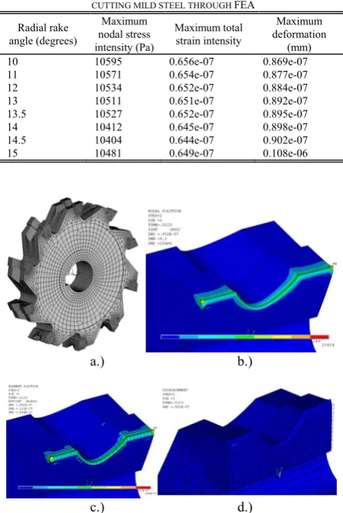
The transient dynamic analysis is carried out for a total time domain of 0.0625 sec (for cutter angle rotation of 30°), with a time step size of 0.0125 sec. A number of iterations were performed within the prescribed limiting range of radial rake angles from 10º to 15º [15]. For the dynamic conditions, Table V shows the maximum values of nodal stress intensity distribution, deformation and elemental total strain intensity distribution of special shaped milling cutter at radial rake angles in the range of 10º to 15º. In this manuscript, for the sake of simplicity, Figs. 6b-6d) show the results of stresses, strains and displacements at tool radial rake angle of 14.5º. The results tabulated in Table V shows that the optimum radial rake angle is 14.5º, where it minimizes the effective stress to reach a maximum value of 10404 Pa.
As per the feedback of the transient dynamic analysis results, the special shaped milling cutter for the above two cases is re-designed and its geometry is optimized. The accuracy of the simulated physical phenomena may be
TABLEIII
MAXIMUM VALUES OF NODAL STRESS INTENSITY, TOTAL STRAIN INTENSITY AND DEFORMATION OF SPECIAL MILLING CUTTER DESIGNED FOR
CUTTING LEATHER SOLE THROUGH FEA
Radial rake angle (degrees)
Maximum nodal stress intensity (Pa)
Maximum total strain intensity
Maximum deformation
(mm)
51 293.78 0.290e-08 0.681e-08
52 275.0 0.250e-08 0.659e-08
53 299.35 0.323e-08 0.746e-08
53.5 301.25 0.334e-08 0.771e-08
54 288.75 0.297e-08 0.715e-08
55 426.63 0.378e-08 0.880e-08
56 323.95 0.343e-08 0.890e-08
57 482.237 0.550e-08 0.110e-07
TABLEIV
MECHANICAL AND THERMAL PROPERTIES OF TOOL INSERT (HSS) AND WORK PIECE (MILD STEEL AISI1020)
Materials High Speed Steel Mild Steel AISI 1020
Density (kg/m3) 7980 7870
Young’s modulus, E (GPa) 210 200
Poisson’s ratio, n 0.30 0.29
Tensile strength (MPa) 970 394.7 Thermal conductivity (W/m°C) 20.9 51.9
Yield stress, sy (MPa) - 294.8
TABLEV
MAXIMUM VALUES OF NODAL STRESS INTENSITY, TOTAL STRAIN INTENSITY AND DEFORMATION OF SPECIAL MILLING CUTTER DESIGNED FOR
CUTTING MILD STEEL THROUGH FEA
Radial rake angle (degrees)
Maximum nodal stress intensity (Pa)
Maximum total strain intensity
Maximum deformation
(mm)
10 10595 0.656e-07 0.869e-07
11 10571 0.654e-07 0.877e-07
12 10534 0.652e-07 0.884e-07
13 10511 0.651e-07 0.892e-07
13.5 10527 0.652e-07 0.895e-07
14 10412 0.645e-07 0.898e-07
14.5 10404 0.644e-07 0.902e-07
15 10481 0.649e-07 0.108e-06
a.) b.)
c.) d.)
[image:5.595.302.549.374.743.2]considered reasonable and is within acceptable limits. The cost parameter could not be compared due to lack of any similar work published in the literature.
V. CONCLUSIONS AND DISCUSSION
This work illustrates an advanced modeling paradigm that can be used to accurately model a special shaped milling cutter and thus, opens up avenues to define conveniently various customized cutters. Here, different design activities, such as geometric modeling, finite element analysis and design improvements have been integrated. As is evident, the approach illustrated in this paper is flexible and easy to use. This approach can also be used to design any complex mechanical component e.g. in the domain of bioCAD, custom implants in orthopedics. The main conclusions, which can be deduced from the present work, can be summarized as follows:
● An accurate surface model of the special shaped milling cutter is developed and it can be used to generate the 3D models of similar tools along with numerous technological applications and thus, opens up various probable areas of work.
● Finite element analysis results of the existing cutter designed for shaping leather objects shows that on the basis of simulation of various cutter models, the optimum radial rake angle is 52º.; This radial rake angle gives the minimum value of effective stress intensity at the cutting zone with minimum total strain intensity distribution. The cutter designed for leather industries is re-designed from radial rake angle of 55º to 52º.
● The special milling cutter generated for form generation in mild steel is re-designed for the optimum radial rake angle of 14.5º as per the feedback from the analysis.
● The two illustrations shown in the present paper highlights that the proposed modeling methodology developed in the work is generic in nature and hence one can develop the families of special cutters with great ease.
ACKNOWLEDGMENT
The authors would like to acknowledge and thank the Science and Engineering Research Council (SERC) of the Department of Science and Technology (DST) New Delhi, India for providing the funds for the R&D project, Ref. SR/S3/MERC-0038/2008.
REFERENCES
[1] A. Vijayaraghavan and D. A. Dornfeld, “Automated drill modeling for drilling process simulation,” Journal of Computing and
Information Science in Engineering, vol. 7, no. 3, pp. 276-282; 2007.
[2] H. C. Kuo and L. J. Wu, “A study on the evaluation of a model of the precise outside of the roller nest mill cutter,” Journal of Materials
Processing Technology, vol. 117, pp. 178-182; 2001.
[3] P. Tandon and M. R. Khan, “Three dimensional modeling and finite element simulation of a generic end mill,” Computer-Aided Design,
vol. 41, no. 2, pp. 106-114; 2009.
[4] P. Tandon, P. Gupta and S. G. Dhande, “Geometric modeling of fluted cutters,” ASME Journal of Computing and Information Science
in Engineering, 021007(1), pp. 1-15; 2008.
[5] N. K. Jha and K. Hornik, “Integrated computer-aided optimal design and finite element analysis of a plain milling cutter,” Applied
Mathematical Modeling, vol. 19, pp. 343-353; 1995.
[6] A. J. Shih, “Finite element analysis of the rake angle effects in orthogonal metal cutting,” International Journal of Mechanical
Science, vol. 38, no. 1, pp. 1-17; 1996.
[7] S. P. Lo, “An analysis of cutting under different rake angles using the finite element method,” Journal of Materials Processing Technology, vol. 105, pp. 143-151; 2000.
[8] M. A. Tawfiq and S. K. Shahab, “A finite element analysis of orthogonal machining using different tool edge geometries,”
Engineering & Technology, vol. 25, no. 4, pp. 569-583; 2007.
[9] J. M. Hsieh and Y. C. Tsai, “Geometric modeling and grinder design for toroid-cone shaped cutters,” International Journal of Advanced
Manufacturing Technology, vol. 29, pp. 912-921; 2006.
[10] S. P. Radzevich, “A novel method for mathematical modeling of a form-cutting-tool of the optimum design,” Applied Mathematical
Modeling, vol. 31, pp. 2639-2654; 2007.
[11] G. C. Wang, K. H. Fuh and B. H. Yarn, “Geometry design model of a precise form milling cutter based on the machining characteristics,”
International Journal of Advanced Manufacturing Technology, vol.
34, pp. 1072-1087; 2007.
[12] S. P. Radzevich, “A novel design of cylindrical hob for machining of precision involute gears,” ASME Journal of Mechanical Design, vol. 129, pp. 334-345; 2007.
[13] J. K. Hsieh, H. C. Tseng and S. L. Chang, “A novel hob cutter design for the manufacture of spur-typed cutters,” Journal of Materials
Processing Technology, vol. 209, pp. 847-855; 2009.
[14] D. F. Rogers and J. A. Adams, Mathematical Elements of Computer
Graphics. New York: McGraw-Hill, 1990.