4192
Abstract— Nowadays distributed generation systems are
widely occupying there place in the power generation. In this paper a new neutral point clamped with a control topology that enables both islanded and grid-tied operations is proposed with no need for switching between two corresponding controllers or critical islanding detection. The proposed control strategy composes of an inner inductor current loop, and a novel voltage loop in the synchronous reference frame. Here inverter is regulated as a current source just by the inner inductor current loop in grid-tied operation, and the voltage controller is automatically activated to regulate the load voltage upon the occurrence of islanding. The NPC inverter needs a neutral DC terminal which is provided by a buck converter. Finally the waveforms of the grid current in the grid-tied mode and the load voltage in the islanding mode with a proposed topology are observed and analyzed by implementing the proposed system in MATLAB/Simulink environment.
Index Terms— NPC (Neutral point clamped), buck converter,
Distributed generation (DG), islanding, load current, seamless transfer, three-phase inverter, unified control.
I. INTRODUCTION
enewable energy resources are being widely used now a days for power generation. Three phase inverter implemented in the unified control strategy is effective and gives the better inductor current [1]. Distributed generation (DG) is emerging as a viable alternative when renewable or nonconventional energy resources are available, such as wind turbines, photovoltaic arrays, fuel cells, micro turbines [2], [4]. Most of these resources are connected to the utility through power electronic interfacing converters, i.e., three-phase inverter. Moreover, DG is a suitable form to offer high reliable electrical power supply, as it is able to operate either in the grid-tied mode or in the islanded mode [3]. In the grid-tied operation, DG deliveries power to the utility and the local critical load. Upon the occurrence of utility outage, the islanding is formed. Under this circumstance, the DG must be tripped and cease to energize the portion of utility as soon as possible according to IEEE Standard 929-2000 [5]. However, in order to improve the power reliability of some local critical load, the DG should disconnect to the utility and continue to feed the local critical
load [6]. The load voltage is key issue of these two operation modes, because it is fixed by the utility in the grid-tied operation, and formed by the DG in the islanded mode, respectively. Therefore, upon the happening of lonely i.e., islanding, DG must take over the load voltage as soon as possible, in order to reduce the transient in the load voltage. And this issue brings a challenge for the operation of DG. Droop-based control is used widely for the power sharing of parallel inverters [12], [13], which is called as voltage mode control in this paper, and it can also be applied to DG to realize the power sharing between DG and utility in the grid-tied mode [14]. In this situation, the inverter is always regulated as a voltage source by the voltage loop, and the quality of the load voltage can be guaranteed during the transition of operation modes. However, the limitation of this approach is that the dynamic performance is poor, because the bandwidth of the external power loop, realizing droop control, is much lower than the voltage loop. Moreover, the grid current is not controlled directly, and the issue of the inrush grid current during the transition from the islanded mode to the grid-tied mode always exists, even though phase locked loop (PLL) and the virtual inductance are adopted. In the hybrid voltage and current mode control, there is a need to switch the controller when the operation mode of DG is changed. During the interval from the occurrence of utility outage and switching the controller to voltage mode, the load voltage is neither fixed by the utility, nor regulated by the DG, and the length of the time interval is determined by the islanding detection process. Therefore, the main issue in this approach is that it makes the quality of the load voltage heavily reliant on the speed and accuracy of the islanding detection method [7]-[11].
This paper proposes a unified control strategy that avoids the aforementioned shortcomings. First, the traditional inductor current loop is employed to control the Neutral point clamped (NPC) inverter with a buck converter which gives neutral point in the dc voltage in DG to act as a current source with a given reference in the synchronous reference frame (SRF). Second, a novel voltage controller is presented to supply reference for the inner inductor current loop, where a proportional-plus-integral (PI) compensator and a proportional (P) compensator are employed in D-axis and Q-axis, respectively. In the grid-tied operation, the load voltage is dominated by the utility, and the voltage compensator in
D-Repalle Naga durga rao1, Kondapalli Paparao2
PG Student, Department of EEE, KIET, Kakinada, India.1 Asst. Professor, Department of EEE, KIET, Kakinada, India.2
A Novel Unified Control Strategy for
Three-Phase Inverter in Distributed Generation
axis is saturated, while the output of the voltage compensator in Q-axis is forced to be zero by the PLL. Therefore, the reference of the inner current loop cannot regulated by the voltage loop, and the DG is controlled as a current source just by the inner current loop. Upon the occurrence of the grid outage, the load voltage is no more determined by the utility, and the voltage controller is automatically activated to regulate the load voltage. These happen naturally, and, thus the proposed control strategy does not need a forced switching between two distinct sets of controllers. Further, there is no need to detect the islanding quickly and accurately, and the islanding detection method is no more critical in this approach. Moreover, the proposed control strategy, benefiting from just utilizing the current and voltage feedback control, endows a better dynamic performance, compared to the voltage mode control. Third, the proposed control strategy is enhanced by introducing a unified load current feed forward, in order to deal with the issue caused by the nonlinear local load, and this scheme is implemented by adding the load current into the reference of the inner current loop. In the grid-tied mode, the DG injects harmonic current into the grid for compensating the harmonic component of the grid current, and thus, the harmonic component of the grid current will be mitigated. Moreover, the benefit of the proposed load current feed forward can be extended into the islanded operation mode, due to the improved quality of the load voltage. The rest of this paper is arranged as follows. Section II describes the proposed unified control strategy for three-phase neutral point clamped inverter in DG, including the power stage of DG, the basic idea, and the control diagram. The detailed operation principle of DG with the proposed control strategy is illustrated in Section III. The parameter design and small signal analysis of the proposed control system are given in Section IV. Section V investigates
the proposed control strategy by simulation results in MATLAB/Simulink environment. Finally, the concluding remarks are given in Section VI.
II. PROPOSEDCONTROLSTRATEGY A. Power Stage
This paper presents a unified control strategy for a three-phase neutral point clamped inverter in DG to operate in both islanded and grid-tied modes. The schematic diagram of the DG based on the proposed control strategy is shown by Fig. 1. The DG is equipped with a three-phase interface inverter terminated with a LC filter. The primary energy is converted to the electrical energy, which is then converted to dc by the front-end power converter, and the output dc voltage is regulated by it. Therefore, they can be represented by the dc voltage source Vdc in Fig. 1. In the ac side of inverter, the local critical load is connected directly. It should be noted that there are two switches, denoted by Su and Si , respectively, in Fig. 1, and their functions are different. The inverter transfer switch Si is controlled by the DG, and the utility protection switch Su is governed by the utility. When the utility is normal, both switches Si and Su are ON, and the DG in the
grid-tied mode injects power to the utility. When the utility is in fault, the switch Su is tripped by the utility instantly, and then the islanding is formed. After the islanding has been confirmed by the DG with the islanding detection scheme [6]-[10], the switch Si is disconnected, and the DG is transferred from the grid-tied mode to the islanded mode. When the utility is restored, the DG should be resynchronized with the utility first, and then the switch Si is turned ON to connect the DG with the grid.
B. Basic Idea
With the hybrid voltage and current mode control [17]-[40], the inverter is controlled as a current source to generate the reference power (PDG + jQDG ) in the grid-tied mode. And its
output power (PDG + jQDG) should be the sum of the power
injected to the grid Pg + jQg and the load demand Pload +
jQload , which can be expressed as follows by assuming that the
load is represented as a parallel RLC circuit.
(1)
(2) In (1) and (2), Vm and ω represent the amplitude and frequency of the load voltage, respectively. When the nonlinear local load is fed, it can still be equivalent to the parallel RLC circuit by just taking account of the fundamental component. During the time interval from the instant of islanding happen-ing to the moment of switching the control system to voltage mode control, the load voltage is neither fixed by the utility nor regulated by the inverter, so the load voltage may drift from the normal range [6]. And this phenomenon can be explained as below by the power relationship. During this time interval, the inverter is still controlled as a current source, and its output power is kept almost unchanged. However, the power injected to
utility decreases to zero rapidly, and then the power consumed by the load will be imposed to the output power of DG. If both active power Pg and reactive power Qg injected
into the grid are positive in the grid-tied mode, then Pload and
Qload will increase after the islanding happens, and the
amplitude and frequency of the load voltage will rise and drop, respectively, according to (1) and (2).
With the previous analysis, if the output power of inverter PDG + jQDG could be regulated to match the load demand by
changing the current reference before the islanding is confirmed, the load voltage excursion will be mitigated. And this basic idea is utilized in this paper. In the proposed control strategy, the output power of the inverter is always controlled by regulating the three-phase inductor current iLabc , while the magnitude and frequency of the load voltage vC abc are
monitored. When the islanding happens, the magnitude and frequency of the load volt-age may drift from the normal range, and then they are controlled to recover to the normal range automatically by regulating the output power of the inverter.
4194 C. Control Scheme
Fig. 2 describes the overall block diagram for the proposed unified control strategy, where the inductor current iLabc , the
utility voltage vgabc , the load voltage vC abc , and the load
current iLLabc are sensed. And the three-phase neutral point
clamped inverter is controlled in the SRF, in which, three phase variable will be represented by dc quantity. The control diagram is mainly composed by the inductor current loop, the PLL, and the current reference generation module. In the inductor current loop, the PI compensator is employed in both D- and Q-axes,
Fig. 1. Schematic diagram of the DG based on the proposed control strategy.
Fig. 2. Overall block diagram of the proposed unified control strategy.
Fig. 3. Block diagram of the current reference generation module.
and a decoupling of the cross coupling denoted by ω0 Lf 1/kPW M is implemented in order to mitigate the couplings due to the inductor. The output of the inner current loop ddq ′, together with the decoupling of the capacitor voltage denoted by 1/kPW M , sets the reference for the standard space vector modulation that controls the switches of the three-phase neutral point clamped inverter. It should be noted that kPW M denotes the voltage gain of the inverter, which equals to half of the dc voltage in this paper.
The PLL in the proposed control strategy is based on the SRF PLL [50], [51], which is widely used in the three-phase power converter to estimate the utility frequency and phase. Furthermore, a limiter is inserted between the PI compensator GPLL and the integrator, in order to hold the frequency of the load voltage within the normal range in the islanded operation. In Fig. 2, it can be found that the inductor current is regulated to follow the current reference iLref dq , and the phase of the current is synchronized to the grid voltage vgabc
.If the current reference is constant, the inverter is just controlled to be a current source, which is the same with the traditional grid-tied inverter. The new part in this paper is the
current reference generation module shown in Fig. 2, which regulates the current reference to guarantee the power match between the DG and the local load and enables the DG to operate in the islanded mode. Moreover, the unified load current feedforward, to deal with the nonlinear local load, is also implemented in this module. The block diagram of the proposed current reference generation module is shown in Fig. 3, which provides the current reference for the inner current loop in both grid-tied and islanded modes. In this module, it can be found that an unsymmetrical structure is used in D- and Q-axes. The PI compensator is adopted in D-axes, while the P compensator is employed in Q-axis. Besides, an extra limiter is added in the D-axis. More-over, the load current feedforward is implemented by adding the load current iLLdq to the final inductor current reference iLref dq . The benefit brought by the unique structure in Fig. 3 can be represented by two parts: 1) seamless transfer capability without critical islanding detection; and 2) power quality improvement in both grid-tied and islanded operations. The current reference iLredq composes of four parts in D- and Q-axes respectively:
1) the output of voltage controller iref dq ;
2) the grid current reference Igref dq ;
3) the load current iLLdq ; and
4) the current flowing through the filter capacitor Cf .
In the grid-tied mode, the load voltage vC dq is clamped by the utility. The current reference is irrelevant to the load voltage, due to the saturation of the PI compensator in D-axis, and the output of the P compensator being zero in Q-axis, and thus, the inverter operates as a current source. Upon occurrence of islanding, the voltage controller takes over automatically to control the load voltage by regulating the current reference, and the inverter acts as a voltage source to supply stable voltage to the local load; this relieves the need for switching between different control architectures. Another distinguished function of the current reference generation module is the load current feedforward. The sensed load current is added as a part of the inductor current reference iLref dq to compensate the harmonic component in the grid current under nonlinear local load. In the islanded mode, the load current feedforward operates still, and the disturbance from the load current, caused by the nonlinear load, can be suppressed by the fast inner inductor current loop, and thus, the quality of the load voltage is improved The inductor current control in Fig. 2 was proposed in previous publications for grid-tied operation of DG [18], and the motivation of this paper is to propose a unified control strategy for DG in both grid-tied and islanded modes, which is represented by the current reference generation module in Fig. 3. The contribution of this module can be summarized in two aspects. First, by introducing PI compensator and P compensator in D-axis and Q-D-axis respectively, the voltage controller is inactivated in the grid-tied mode and can be automatically activated upon occurrence of islanding. Therefore, there is no need for switching different controllers or critical islanding detection, and the quality of the load voltage during the transition from the grid-tied mode to the islanded mode can be improved. The second contribution of this module is to present the load current feedforward to deal with the issue caused by
the nonlinear local load, with which, not only the waveform of the grid current in grid-tied is improved, but also the quality of the load voltage in the islanded mode is enhanced. Besides, it should be noted that a three-phase unbalanced local load cannot be fed by the DG with the proposed control strategy, because there is no flow path for the zero sequence current of the unbalanced load, and the regulation of the zero sequence current is beyond the scope of the proposed control strategy
III. PRINCIPLE OF DISTRIBUTION GENERATION
The operation principle of DG with the proposed unified control strategy will be illustrated in detail in this section, and there are in total four states for the DG, including the grid-tied mode, transition from the grid-tied mode to the islanded mode, the islanded mode, and transition from the islanded mode to the grid-tied mode.
A. Grid-Tied Mode
When the utility is normal, the DG is controlled as a current source to supply given active and reactive power by the inductor current loop, and the active and reactive power can be given by the current reference of D- and Q-axis independently. First, the phase angle of the utility voltage is obtained by the PLL, which consists of a Park transformation expressed by (3), a PI compensator, a limiter, and an integrator
(3) Second, the filter inductor current, which has been transformed into SRF by the Park transformation, is fed back and compared with the inductor current reference iLref dq , and the inductor current is regulated to track the reference iLref dq bythe PI compensator GI .The reference of the inductor current loop iLref dq seems complex and it is explained as below. It is assumed that the utility is stiff, and the three-phase utility voltage can be expressed as
(4) where Vg is the magnitude of the grid voltage, and θ∗ is the
actual phase angle. By the Park transformation, the utility voltage is transformed into the SRF, which is shown as
(5)
vgq is regulated to zero by the PLL, so vgd equals the magnitude
of the utility voltage Vg . As the filter capacitor voltage equals
the utility voltage in the gird-tied mode, vCd equals the
magnitude of the utility voltage Vg , and vCq equals zero, too.
In the D-axis, the inductor current reference iLref d can be
4196
(6)
The first part is the output of the limiter. It is assumed that the given voltage reference Vmax is larger than the magnitude of the utility voltage vCd in steady state, so the PI compensator, denoted by GV D in the following part, will saturate, and the limiter outputs its upper value Igref d. The second part is the load current of D-axis iLLd, which is determined by the characteristic of the local load. The third part is the proportional part −ω0Cf · vCq, where ω0 is the rated angle frequency, and Cf is the capacitance of the filter capacitor. It is fixed as vCq depends on the utility voltage. Consequently, the current reference iLref d is imposed by the given reference Igref d and the load current iLLd, and is independent of the load voltage.
In the Q-axis, the inductor current reference iLref q consists
of four parts as
(7)
where kGvq is the parameter of the P compensator, denoted by GV Q in the following part. The first part is the output of GV Q,
which is zero as the vCq has been regulated to zero by the PLL.
The second part is the given current reference Igref q , and the
third part represents the load current in Q-axis. The final part is the proportional part −ω0Cf · vCd, which is fixed since vCd
depends on the utility voltage. Therefore, the current reference
iLref q cannot be influenced by the external voltage loop and is
determined by the given reference Igref q and the load current iLLq .
B. Transition From the Grid-Tied Mode to the Islanded Mode
In the grid-tied mode, it is assumed that the DG injects activeand reactive power into the utility, which can be expressed by (8) and (9), and that the local critical load, shown in (10), represented by a series connected RLC circuit with the lagging power factor
(8)
(9)
(10)
When islanding happens, igd will decrease from positive to
zero, and igq will increase from negative to zero. At the same
time, the load current will vary in the opposite direction. The load voltage in D- and Q-axes is shown by (11) and (12), and each of them consists of two terms. It can be found that the load voltage in D-axis vCd will increase as both terms increase.
However, the trend of the load voltage inQ-axis vCq is
uncertain because the first term decreases and the second term increases, and it is not concerned for a while
(11)
(12)
With the increase of the load voltage in D-axis vCd, when it
reaches and exceeds Vmax, the input of the PI compensator
GV D will become negative, so its output will decrease. Then,
the output of limiter will not imposed to Igref d any longer, and
the current reference iLref d will drop. With the regulation of
the inductor current loop, the load current in D-axis iLLd will
decrease. As a result, the load voltage in D-axis vCd will drop
and recover to Vmax.
C. Islanded Mode
In the islanded mode, switching Si and Su are both in OFF state. The PLL cannot track the utility voltage normally, and the angle frequency is fixed. In this situation, theDGis controlled as a voltage source, because voltage compensator
GV D and GV Q can regulate the load voltage vCdq . The voltage
references in D and Q-axis are Vmax and zero, respectively. And the magnitude of the load voltage equals to Vmax approximately, which will be analyzed in Section IV. Consequently, the control diagram of the three-phase inverter in the islanded mode can be simplified as shown in Fig. 4.
In Fig. 4, the load current iLLdq is partial reference of the
inductor current loop. So, if there is disturbance in the load current, it will be suppressed quickly by the inductor current loop, and a stiff load voltage can be achieved.
Fig. 4. Simplified block diagram of the unified control strategy when DG operates in the islanded mode.
D. Transition From the Islanded Mode to the Grid-Tied Mode
If the utility is restored and the utility switch Su is ON, the DG should be connected with utility by turning on switch Si . However, several preparation steps should be performed before turning on switch Si . First, as soon as utility voltage is restored, the PLL will track the phase of the utility voltage. As a result, the phase angle of the load voltage vCabc will follow
the grid voltage vgabc. If the load voltage vCabc is in phase with
the utility voltage, vgd will equal the magnitude of the utility
voltage according to (5). Second, as the magnitude of the load voltage Vmax is larger than the utility voltage magnitude Vg ,
the voltage reference Vref will be changed to Vg by toggling the
selector S from terminals 1 to 2. As a result, the load voltage will equal to the utility voltage in both phase and magnitude. Third, the switch Si is turned on, and the selector S is reset to terminal 1. In this situation, the load voltage will be held by the utility. As the voltage reference Vref equals Vmax, which is larger than the magnitude of the utility voltage Vg, so the
PI compensator GV D will saturate, and the limiter outputs its
upper value Igref d. At the same time, vCq is regulated to zero
by the PLL according to (5), so the output of GV Q will be
zero. Consequently, the voltage regulators GV D and GV Q are
inactivated, and the DG is controlled as a current source just by the inductor current loop.
IV. ANALYSISANDDESIGN
The conventional three-phase inverter with control strategy is analyzed and designed in both steady state and transient state in the reference paper [1]. So in this section a new Neutral point clamped (NPC) with a buck converter is designed to achieve maximum efficiency.
NPC inverter needs a three input terminals namely positive dc, negative dc and a neutral dc terminal and these three terminal are provided by a buck convert which bring a neutral terminal along with two output dc terminals.
A .Buck converter
Buck converter which acts as a voltage balancer is shown in Fig. 4, in which a neutral line is built by using a voltage balancer achieving two same voltage levels for requirements of different types of loads, such as unbalanced loads, half-bridge converter and inverter, and so on. The proposed voltage balancer—a dual-buck half-bridge voltage balancer—is shown in Fig. 4, which is made up of a left bridge leg (S1,D1, L1), a right bridge leg (S2,D2, L2),and a neutral line LN usually connected to the earth ground. If the conventional driving technology is adopted between the switches S1 and S2, the two-inductor currents iL1 and iL2 will always exist during a switching period, and the unbalanced load current value (iRLoad2 − iRLoad1) is equal to the different value between the current average value iL1 and iL2.
Fig.4. Proposed dual buck half bridge voltage balancer
Thus, the two inductor currents will cause additional power losses which leads to system inefficiency. It is very essential to have a control strategy that can drive the left bridge leg and the right bridge leg, respectively, based on the different power quantity of the balanced and unbalanced loads. Hence
voltage balancer is placed near a converter to balance positive and negative voltages. It is also possible to place it near load side.
B . Neutral point clamped (NPC) inverter
The neutral point converter proposed in fig 5 was essentially a three-level diode-clamped inverter. Several researchers have reported that NPC inverter is very efficient when compared with the traditional inverters. These inverter will be used in static var compensation, variable speed motor drives, and high-voltage system interconnections. A three-phase six-level diode-clamped inverter is shown in Figure 5. Each of the three phases of the inverter shares a common dc bus, which has been subdivided by five capacitors into six levels. The voltage across each capacitor is Vdc, and the voltage stress across each switching device is limited to Vdc through the clamping diodes.
Fig.5 Neutral point clamped inverter
Advantages of NPC:
All of the phases share a common dc bus, which minimizes the capacitance requirements of the converter. For this reason, a back-to-back topology is not only possible but also practical for uses such as a high-voltage back-to-back inter-connection or an adjustable speed drive.
The capacitors can be pre-charged as a group.
Efficiency is high for fundamental frequency switching.
V. SIMULATION RESULTS
To analyze the proposed control strategy, the simulation has been done in PSIM. The power rating of a Neutral clamped inverter is 3 kW in the simulation. The parameters in the simulation are shown in Table II. The RMS of the rated phase voltage is 115 V, and the voltage reference Vmax as 10% higher than the rated value. The rated utility
4198 frequency is 50 Hz, and the upper and the lower values of
the limiter in the PLL are given as 0.2 Hz higher and lower than the rated frequency, respectively.
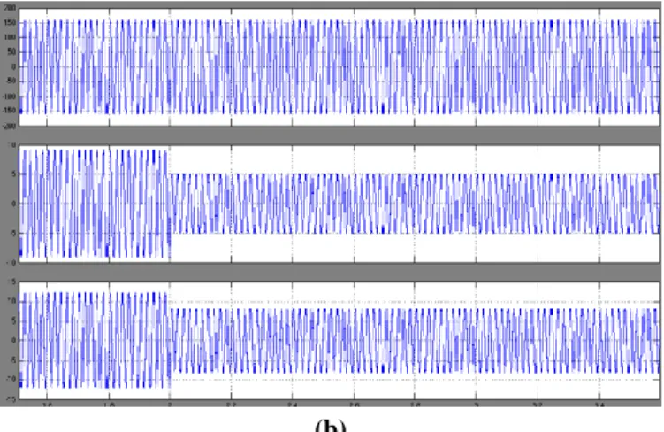
In the grid-tied mode, the dynamic performance of the conventional voltage mode control and the proposed unified control strategy is compared by stepping down the grid current reference from 9 A to 5 A. The simulation result of the voltage mode control is shown in Fig. 6(a), and the current reference is changed at the moment of 2 s. It is found that dynamic process is less than 5 ms. In the proposed control strategy also, the simulation result is represented in Fig. 6(b) dynamic process is very less than the previous one. Comparing the simulation results above, it can be seen that the dynamic performance of the proposed control strategy is better than the conventional voltage mode control.
During the transition from the grid-tied mode to the islanded mode, the proposed unified control strategy is compared with the hybrid voltage and current mode control, and the simulation scenario is shown as follows: 1) Initially, the utility is normal, and the DG is connected with the utility; 2) at 0.5 s, islanding happens; and 3) at 0.52 s, the islanding is confirmed.
Simulate results with the hybrid voltage and current mode control is shown in Fig. 7(a). It can be seen that the grid current drop to zero at 0.5 s, and that the load voltage is distorted from 0.5 to 0.52 s. Then, the load voltage is recovered to the normal value after 0.52 s. Fig. 7(b) presents the simulate results with the proposed control strategy with neutral point clamped (NPC )inverter. Initially, the magnitude of grid current is 9 A and follows the current reference Igref dq . The magnitude and frequency of the load voltage are held by the utility. After the islanding happens, the amplitude of the load voltage increases a little to follow the voltage reference Vmax, and the output current of DG decreases autonomously to match the load power demand with a smooth inductor current.
Comparing the simulation results above, it can be found that the voltage quality is improved deeply by the proposed control strategy in the transition from the grid-tied mode to the islanded mode, and the speed of the islanding detection is no more critical.
(a)
(b)
Fig. 6. Simulation waveforms of load voltage vC a , grid current iga, and inductor current iLa when DG is in the grid-tied mode under condition of the step down of the grid current reference from 9 A to 5 A with: (a) conventional voltage mode control, and (b) proposed NPC control strategy.
(a)
(b)
Fig. 7. Simulation waveforms of load voltage vC a , grid current iga, and inductor current iLa when DG is transferred from the grid-tied mode to the islanded mode with: (a) conventional hybrid voltage and current mode control, and (b) proposed NPC control strategy.
VI. CONCLUSION
A new control topology was proposed for three-phase neutral point clamped (NPC) inverter in DG to operate in both islanded and grid-tied modes, with no need for switching between two different control architectures or critical islanding detection. A novel voltage controller was presented. It is inactivated in the grid-tied mode, and the DG operates as a current source with fast dynamic performance. Upon the utility outage, the voltage controller can automatically be activated to regulate the load voltage. Moreover, a novel load current feedforward was proposed, and it can improve the waveform quality of both the grid current in the grid-tied mode and the load voltage in the islanded mode. The proposed control strategy was verified by the simulation results.
REFERENCES
[1] Zeng Liu, Jinjun Liu, ―A Unified Control Strategy for Three-Phase Inverter in Distributed Generation,‖ IEEE Trans. on Power Electronics, Vol. 29, No. 3,pp. 1176-1191, March 2014.
[2] R. C. Dugan and T. E. McDermott, ―Distributed generation,‖ IEEE Ind.Appl. Mag., vol. 8, no. 2, pp. 19–25, Mar./Apr. 2002.
[3] R. H. Lasseter, ―Microgrids and distributed generation,‖ J. Energy Eng.,vol. 133, no. 3, pp. 144–149, Sep. 2007.
[4] C. Mozina, ―Impact of green power distributed generation,‖ IEEE Ind.Appl. Mag., vol. 16, no. 4, pp. 55–62, Jul./Aug. 2010.
[5] IEEE Recommended Practice for Utility Interface of Photovoltaic(PV)Systems, IEEE Standard 929-2000, 2000. [6] IEEE Standard for Interconnecting Distributed Resources with ElectricPower Systems, IEEE Standard 1547-2003, 2003. [7] J. Stevens, R. Bonn, J. Ginn, and S. Gonzalez, Development and Testingof an Approach to Anti-Islanding in Utility-Interconnected Photovoltaic
Systems. Livermore, CA, USA: Sandia National Laboratories, 2000.
[8] A. M. Massoud, K. H. Ahmed, S. J. Finney, and B. W. Williams, ―Harmonicdistortion-based island detection technique for inverter-based distributed
generation,‖ IET Renewable Power Gener., vol. 3, no. 4, pp. 493–507, Dec. 2009.
[9] T. Thacker, R. Burgos, F. Wang, and D. Boroyevich, ―Single-phase islanding detection based on phase-locked loop stability,‖ in Proc. 1st IEEE
Energy Convers. Congr. Expo., San Jose, CA, USA, 2009, pp. 3371–3377.
[10] S.-K. Kim, J.-H. Jeon, J.-B. Ahn, B. Lee, and S.-H. Kwon, ―Frequencyshift acceleration control for anti-islanding of a distributed-generation inverter,‖ IEEE Trans. Ind. Electron., vol. 57, no. 2, pp. 494–504, Feb. 2010.
[11] A. Yafaoui, B. Wu, and S. Kouro, ―Improved active frequency drift antiislanding detection method for grid connected photovoltaic systems,‖ IEEE Trans. Power Electron., vol. 27, no. 5, pp. 2367–2375, May 2012.
[12] J. M. Guerrero, L. Hang, and J. Uceda, ―Control of distributed uninterruptible power supply systems,‖ IEEE
Trans. Ind. Electron., vol. 55, no. 8, pp. 2845–2859, Aug. 2008.
[13] M. C. Chandorkar, D. M. Divan, and R. Adapa, ―Control of parallel connected inverters in standaloneACsupply systems,‖ IEEE Trans. Ind. Appl., vol. 29, no. 1, pp. 136–143, Jan./Feb. 1993.
[14] Y. Li, D. M. Vilathgamuwa, and P. C. Loh, ―Design, analysis, and realtime testing of a controller for multibus microgrid system,‖ IEEE Trans. Power Electron., vol. 19, no. 5, pp. 1195–1204, Sep. 2004.