MATLAB/Simulink Based Design and Simulation of
Speed Control of Three Phase Slip Ring Induction
Motor Using Chopper
Chandana Sooji1, Mala Bogar2, Megha Dhage3,Shuklambari Madiwalar4, Vijayshree Horadi5,Asst.Prof.Chaitanya J6 1,2,3,4,5
4th SEM Students in Department of Electrical and Electronics Engineering, KLE.I.T, Hubballi, Karnataka, India. 6
Assistant Professor in Department of Electrical and Electronics Engineering, KLE.I.T, Hubballi, Karnataka, India.
Abstract— In recent years, advancement in power electronics has
created a huge impact on operation and speed control of Induction motor drives. This paper initiates a novel idea to control the speed of three phase induction motor using chopper. As literature suggests, the speed of a three phase induction motor can be controlled either by using armature voltage control technique or by adding external resistance in the rotor circuit manually. The paper deals with developing a power electronic based control system which allows to control the speed of three phase induction motor by overcoming the drawbacks of conventional techniques. In this technique, chopper circuit is so developed such that as duty cycle of the chopper is increased the speed of the three phase induction motor should be increased. Initially, the name plate details of three phase slip ring induction motor whose speed is to be controlled is noted and by conducting No-Load Test and Locked rotor Test on the motor the equivalent electrical circuit is developed. The same is simulated on the MATLAB/Simulink platform with chopper controlled external resistance. The complete system is executed for different duty cycles of chopper to evaluate the control parameters and performance parameters of system. It is found that the high chopper frequency tend to improve the performance of three phase slip ring induction motor drive such as, rotor rectified current, rotor phase current, speed smoothing with reducing the torque pulsation and ripple of rotor rectified current whereas increase in the duty cycle of chopper, the speed of the three phase induction motor is found to be increased. So we conclude that, the proposed technique of speed control is optimum compared to conventional techniques of speed control of three phase slip ring induction motor. Further the same system could be upgraded to wireless speed control platform by providing control signal to circuit from remote place.
Index Terms—DC-DC Converter, Induction motor, PWM Technique.
I. INTRODUCTION
Induction motors are the most widely used electrical motors due to their reliability, low cost and robustness. However, induction motors do not inherently have the capability of variable speed operation. Due to this reason, DC motors found applications in the electrical drives. But the recent
developments in speed control methods of the induction motor have led to their large scale use in almost all electrical drives.
Induction motors are a constant speed machines which account for 90% of the electrical drives used in Industry. Induction motors are usually constructed to work with a small value of slip, normally less than 5% at full load. Therefore the deviation of the motor speed from the synchronous speed is practically very small. However, there are certain applications that require enormous variation of the motor speed. With the increase in availability of high current power electronic devices, smooth and quick variation of external resistance introduced in the rotor circuit of slip ring induction motor to control its speed, can be accomplished electronically.
Schemes employing chopper control resistance can be used to obtain a constant torque, constant speed or any desired characteristics by using a proper feedback circuit along with it. Such circuits are widely used in industrial applications where the drive operation is intermittent such as hoists, cranes, conveyors, lifts, excavators and high starting torque are more important with low starting current to avoid voltage dip. The torque depends on motor resistance. Therefore, increasing the rotor resistance at a constant torque causes a proportionate increase in the motor slip with decrease in rotor speed. Thus, the speed for a given load torque may be varied by varying the rotor resistance.
The function of this resistance is to introduce voltage at rotor frequency, which opposes the voltage induced in rotor winding. Conventionally, the rotor resistance is controlled manually and in discrete steps. The main demerit of this method of speed control is that energy is dissipated in rotor circuit resistance. Because of the waste-fullness of this
method, it is used where speed change are needed for short duration only.
This paper proposes a speed control concept which eliminates the drawbacks of a conventional scheme by using a 3 phase un-controlled bridge rectifier and a chopper controlled external resistance. However, this arrangement for controlling the average value of rotor current (external resistance) introduces the additional problems of discontinuity in the rotor winding currents and voltage spikes across the chopper. These problems can be eliminated by having a filter circuit in the rotor of slip ring induction motor.
II. CONVENTIONAL TECHNIQUE OF SPEED CONTROL
Conventionally, the rotor resistance is controlled manually and in discrete steps. The torque is proportional to product of rotor current and fundamental magnetic flux cutting rotor. The maximum torque is independent of rotor resistance, but the value of slip at which maximum torque occurs is directly proportional to the added rotor resistance. Increase in the rotor resistance does not affect the value of maximum torque but increases the slip. The Equation 1 illustrates that when a high starting torque is required, the R2 should be chosen appropriately to obtain Tmax at stand still.
T = KsEz
2R 2
R22+ s2X22
− − − − − − − − − −(1)
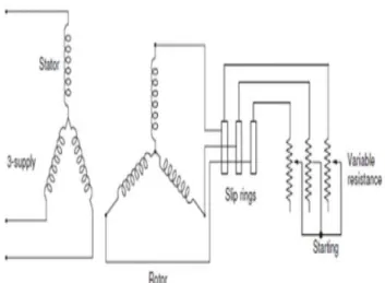
The following Fig. 1 shows conventional method of speed control of three phase slip ring induction motor.
Fig. 1 conventional scheme of speed control
The Following Fig. 2 shows the speed-torque characteristics of a slip ring induction motor for different values of rotor resistances.
Fig. 2 speed-torque characteristics of a slip-ring induction motor
for different values of rotor resistances.
The main drawback of the conventional scheme is, energy is dissipated in rotor circuit resistance. Because of the waste-fullness of the energy, it is used only where speed change is needed for short duration.
III. PROPOSED TECHNIQUE OF SPEED CONTROL With the advent of power semiconductors, the conventional resistance control scheme can be eliminated by using a three-phase rectifier bridge and a chopper controlled external resistance as shown in Fig. 3.
Fig. 3 Proposed method of speed control
A chopper is a power switch which is electronically controlled by a control circuit. When the chopper is in the ON mode of operation, the equivalent resistance in the rotor circuit is R1. When the chopper is in the OFF mode of operation, the equivalent external resistance in the rotor circuit is (R1 + R2). If the chopper is periodically regulated so that, in each chopper period, it is ON for some time and OFF for the rest, it is possible to obtain a variation in equivalent external resistance between R1 and (R1 + R2). Thus the chopper electronically alters the external resistance R2 in a continuous and contactless manner.
The duty cycle (D= ton/(ton + toff)) of the chopper is controlled by a pulse width modulation (PWM) circuit.
This simple arrangement for controlling the average value of rotor current (external resistance) introduces the additional problems of discontinuity in the rotor winding currents and voltage spikes across the chopper. These problems are eliminated by having either a first or second order filter in the rotor circuit.
The following tables, Table-1 to Table-4 give details regarding the electrical parameters of the machine whose speed is to be controlled.
Name Plate Details of the Machine General Parameters:
Table1-1 General parameters of the machine Parameter Specification Phase 3 Phase Frequency 50 Hz Pole 6 Speed 1000 RPM % Efficiency 81 % Power 2.2 KW / 3 H.P Stator:
Table1-2 Details of stator winding Parameter Specification
Voltage 415 V Current 6.6 A Connection Star Connected
Rotor:
Table1-3 Details of rotor winding Parameter Specification
Voltage 120 V Current 11.6 A Connection Star Connected
Initially, the name plate details of three phase slip ring induction motor whose speed is to be controlled is noted and by conducting No-Load Test and Locked rotor Test on the motor the equivalent electrical circuit is developed.
The stator and rotor resistance and inductance as referred to stator determined by conducting No–Load test and Locked Rotor test is shown in Table4,
Table1-4 Details of Equivalent circuit as referred to stator winding of the machine
Parameter Value
Stator Resistance (Rs) 0.7384 Ohm Rotor Resistance (Rr) 0.7402 Ohm Stator Inductance (Ls) 3 mH
Rotor Inductance (Lr) 3 mH Mutual Inductance (Lm) 0.1241 H
Rotor Inertia (J) 0.0343 Kg-m2
Torque (T) 14.85 N-m
The complete proposed system is designed and then simulated on MATLAB/Simulink Platform. The following Fig. 4 shows the Simulink model of the proposed concept.
Fig. 4 Simulink model of the proposed concept.
IV. SIMULATION RESULTS AND DISCUSSION The Simulink model of proposed concept had been simulated for duty ratios varying from 0% to 100% by having fixed external resistance. The procedure was repeated for different external resistance values such as 30 ohm, 60 ohm, 90 ohm and 120 ohm. In the next simulation, the duty cycle was maintained constant first at 50% then at 80% and the switching frequency of chopper was varied from 50 Hz to 4K Hz. The results of both these simulations are shown in Table-5 and Table-6 respectively.
The following Table 5 shows the simulation results of the proposed concept by having the following constraints for the Simulink model Fsw = 50 Hz, Tsw = 0.02 sec, Rext = 30 ohm, T = 14.85 N-m.
The following Table 6 shows the simulation results of the proposed concept for the Simulink model by having the following constraints D = 50%,Rext = 30 ohm,T = 14.85 N-m.
Table-5 Simulation results of effect on speed due to change in duty cycle Duty Cycle in % (Vabc)rms in V (Iabc)rms in A Nmean in RPM Tmean in N-m (Is)mean in A (Ir)mean in A (Vdc)mean in V (Idc)mean in A 0 239.6 7.032 907.1 15.53 -1.079 -0.8054 50.74 3.408 10 239.6 5.718 935.6 13.68 0.4687 0.9534 35.23 3.064 20 239.6 7.079 961.4 14.24 2.208 0.3057 19.78 2.869 30 239.6 6.264 953 14.66 -0.03 -2.934 14.3 4.11 40 239.6 6.089 954.6 13.73 -1.03 -1.039 15.17 3.095 50 239.6 6.115 965 15.04 -0.901 2.806 11.63 2.668 60 239.6 6.658 975 14.7 0.4058 0.2435 5.349 2.915 70 239.6 6.379 977.6 14.69 0.1021 -2.793 3.637 2.871 80 239.6 6.601 981.1 14.83 0.3097 -2.748 2.064 2.838 90 239.6 6.571 978.7 14.04 -0.2036 -1.321 1.489 2.894 100 239.6 6.656 974.8 14.09 1.037 -0.4262 1.037 2.931
Table-6 Simulation results of effect on speed due to change in switching frequency Switching Frequency in Hz (Vabc)rms in V (Iabc)rms in A Nmean in RPM Tmean in N-m (Is)mean in A (Ir)mean in A (Vdc)mean in V (Idc)mean in A 50 239.6 6.466 965.6 14.85 0.596 2.028 12.31 9.485 100 239.6 6.755 970.2 13.61 0.1373 1.914 7.95 6.856 500 239.6 6.062 975.3 14.98 -0.0405 -0.7482 4.46 5.645 1000 239.6 6.272 979.9 15.12 0.045 -2.788 3.021 4.644 1500 239.6 5.904 977.9 15.13 -0.1483 -2.957 2.746 4.592 2000 239.6 6.178 977.7 14.96 -0.0132 -3.114 2.673 4.725 2500 239.6 6.884 978.3 14.62 -0.0509 -2.99 2.203 4.28 3000 239.6 6.813 980.1 14.27 0.095 -2.748 1.873 3.831 4000 239.6 6.814 980 14.24 0.084 -2.751 1.878 3.839 4500 239.6 6.807 980.3 14.33 0.107 -2.745 1.85 3.813 5000 239.6 6.827 979.2 14.21 -0.0601 -2.817 1.968 3.979
The following Fig. 5 shows the nature of three phase input voltage in volts which is fed as input to the stator of three phase induction motor.
Fig. 5 Three phase input voltage to stator
The following Fig. 6 shows the plot of stator current in amperes. As it can be referred from the figure 6 that, the motor draws 10 times more the rated current during starting as there is no back emf available in the circuit then further it settles at the rated current provided a rated load is applied on the motor.
Fig. 6 Plot of stator current
The following Fig. 7 shows the plot of rotor current in amperes.
Fig. 7 Plot of rotor current
The following Fig. 8 shows the plot of speed in rad/sec. As shown in the figure 8 we can observe that the motor is taking more transient time before settling at the constant speed.
Fig. 8 Plot of speed
The following Fig. 9 shows the plot of PWM signal. As shown in the figure 9, we can observe that it is the PWM signal with the duty cycle been set to 50%. However the provision is provided in the model to vary duty cycle from 0% to 100%.
Fig. 9 Plot of PWM signal
The following Fig. 10 shows the plot of change in speed as duty cycle is increased from 0% to 100%. It is observed that as duty cycle of chopper is increased the speed of three phase slip ring induction motor is also increased. Interesting observation from the graph obtained is that the change is not completely a linear it is because of resistance offered during speed control through chopper.
Fig. 10 Plot of speed Vs duty cycle 900 950 1000 0 50 100 150 S p e e d i n R P M Duty Cycle in % Plot of Speed Vs Duty Cycle
The following Fig. 11 shows the plot of change in voltage drop across external resistance as duty cycle is increased from 0% to 100%. It is observed that as the duty cycle of chopper is increased the potential across external resistance decreases. The potential drop across external resistance is proportional to the resistance offered by the external resistance at that duty cycle.
Fig. 11 Plot of voltage drop across external resistance Vs duty cycle
The following Fig. 12 shows the plot of change in speed as switching frequency is varied from 50Hz to 5000 Hz maintaining duty cycle constant at 50%. It is observed that having duty cycle constant, change in switching frequency has got very less effect on the speed of three phase slip ring induction motor.
Fig. 12 Plot of speed Vs switching frequency
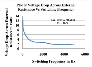
The following Fig. 13 shows the plot of change in voltage drop across external resistance as switching frequency is varied from 50Hz to 5000 Hz. It is observed that keeping duty cycle constant at 50% if switching frequency is altered from 50 Hz to 5000 Hz the voltage drop across external resistance follows a negative exponential curve and attains saturation at 3000 Hz.
Fig. 13 Plot of voltage drop across external resistance Vs switching frequency
The following Fig. 14 shows the comparison plot of change in speed as duty cycle is varied from 0% to 100%. It is observed that as resistance value of external resistance is increased the range of speed control is increased. But as inclusion of resistance in rotor circuit increases power dissipation in rotor circuit increases. Hence there should be a trade-off between speed control range and power dissipation while selecting the value for external resistance across chopper.
Fig. 14 Plot of speed Vs duty cycle 0 10 20 30 40 50 60 0 50 100 150 V o ltage D r o p A c r o ss Ex te r n al R es is tan ce i n V o lts Duty Cycle in %
Plot of Voltage Drop Across External Resistance Vs Duty Cycle
For Rext = 30 ohms
960 965 970 975 980 985 0 2000 4000 6000 S p e e d i n R P M Switching Frequency in Hz Plot of Speed Vs Switching Frequency
For Rext = 30 ohm D = 50% 0 2 4 6 8 10 12 14 0 2000 4000 6000 V o ltage D r o p A c r o ss Ex te r n al R e si stan c e i n V o lts Switching Frequency in Hz Plot of Voltage Drop Across External
Resistance Vs Switching Frequency For Rext = 30 ohm
D = 50% 840 860 880 900 920 940 960 980 1000 0 50 100 150 S p e e d i n R P M Duty Cycle in % Plot of Speed Vs Duty Cycle
Nmean in RPM For 30 ohm Nmean in RPM For 60 ohm Nmean in RPM For 90 ohm Nmean in RPM For 120 ohm
The following Fig. 15 shows the plot of change in speed as switching frequency is varied from 50Hz to 5000 Hz. It is observed that as the duty cycle is increased the switching frequency losses the control on speed and hence gives a constant speed at all switching frequency.
Fig. 15 Plot of speed Vs switching frequency
The following Fig. 16 shows the plot of change in voltage drop across external resistance as duty cycle is increased from 0% to 100%. It is observed that increase in the value of external resistance the potential drop across for a duty cycle is found to be increased, hence increases the range of speed control but affects the performance of the system by introducing a lot of heat in the rotor circuit.
Fig. 16 Plot of voltage drop across external resistance Vs duty cycle
The following Fig. 17 shows the plot of change in voltage across external resistance as switching frequency is varied from 50Hz to 5000 Hz. It is observed that the switching frequency losses the control over the speed if duty cycle value exceeds 50%. Hence voltage drop across the external resistance becomes constant.
Fig. 17 Plot of voltage drop across external resistance Vs switching frequency
V. CONCLUSION
The chopper based speed control circuit for three phase slip ring induction motor is designed and simulated. The effect of duty cycle for different value of external resistance and effect of chopper frequency at different duty cycles for slip ring induction motor is analyzed. Based on the observations and obtained results the following concepts can be concluded,
The speed of slip ring induction motor is increased with increase in the duty cycle for a external resistance added in the rotor circuit.
Low value of chopper frequency causes fluctuation in motor speed and torque pulsation.
Increase in the chopper frequency, decreases the ripple in rotor rectified voltage, speed variation and improves electromagnetic torque characteristics of the motor. 964 966 968 970 972 974 976 978 980 982 984 0 2000 4000 6000 S p e e d i n R P M Switching Frequency in Hz
Plot of Speed Vs Switching Frequency
Nmean in RPM For R = 30 ohm D = 50% Nmean in RPM For R = 30 ohm D = 80% 0 10 20 30 40 50 60 70 80 90 0 50 100 150 V o ltage D r o p A c r o ss Ex te r n al R e si stan c e i n V o lts Duty Cycle in %
Plot of Voltage Drop Across External
Resistance Vs Duty Cycle (Vdc)mean in V For 30 ohm (Vdc)mean in V For 60 ohm (Vdc)mean in V For 90 ohm (Vdc)mean in V For 120 ohm 0 1 2 3 4 5 6 7 8 9 0 2000 4000 6000 V o ltage D r o p A c r o ss Ex te r n al R e si stan c e i n V o lts Switching Frequency in Hz Plot of Voltage Drop Across External
Resistance Vs Switching Frequency
(Vdc)mean in V For R = 30 ohm D = 50% 12.31 (Vdc)mean in V For R = 30 ohm D = 80% 4..245
REFERENCES
[1] M. Ramamoorthi, Senior Member IEEE and NS Wani, Member IEEE “Dynamic Model for Chopper Controlled Slip-Ring Induction Motor” IEEE Trans. On Industrial Electronics and control Instrumentation., vol. IECI-25 ,no. 3, Aug. 2007.
[2] N. S. Wani, "Thyristor controllers for slip-ring induction motors," Ph.D. dissertation (under completion), Dep. Elec. Eng., Indian Institute of Technology, Kanpur, India.
[3] “A Text book of Electrical Technology in SI units Volume II AC and DC Machines”, B.L.Thereja, A.K.Thereja, S. Chand Publication.
[4] "Power Electronics, Converters Applications and Design", John Wiley & Sons, Inc., Book, 1995 Mohan Ned, Undeland Tore M. and Robbins William P.
[5] “Performance and Design of A.C. Machines”, M. G. Say, ELBS and PITMAN.
[6] “Adjustable Speed AC Drive System”, Bimal K. Bose, IEEE Press, 2001.
[7] “Power Electronics: Handbook”, Muhammad H. Rashid, Academy Press, 2001.
[8] “Power Electronics, essential & application”, L. Umanand, ED-2000.
[9] Gopal K. Dubay, “Fundamental of Electrical Drives” Book, 2nd edition, Alpha Science International Ltd. 2001.