International Journal of Science, Engineering and Technology Research (IJSETR) Volume 6, Issue 10, October 2017, ISSN: 2278 -7798
1386
All Rights Reserved © 2017 IJSETR
DESIGN DEVELOPMENT ANALYSIS & TESTING OF
PORTABLE WAIST BELT MOUNTED POWER TOOL
WITH ELLIPTICAL SPRING MOUNT
Shreyash Patil
1Prof. Dr. K.P. Kolhe
21 Departmnt of Mechanical Engineering JSPM’s Imperial College of Engg. And Research Center Wagholi, 2 Departmnt of Mechanical Engineering JSPM’s Imperial College of Engg. And Research Center Wagholi,
Abstract in the process of drilling in false ceiling arear or drilling in the area which is difficult to access for normal working
which is to be done by keeping drilling instrument in hand by an operator may cause uncomfortness as well as more operator fatigue also the vibrations coming from instrument leading to cause physical disorders like Hand-Arm Vibrations, and specific disorders like carpal tunnel syndrome tennis elbow and vibration white finger. In order to get rid of this problem we have designed power tool with flexible shaft with power tool mounted on waist belt with elliptical spring and viscous fluid damper and only tool holder in hand with flexible. As the drive motor is not in hand and it is on waist belt with vibration isolation the weight in hand is less also the small tool holder with gears will give torque amplifications causing less efforts for operator and ease of access to the up-right direction for drilling or hole sawing operations.
(Note that the organization of the body of the paper is at the authors’ discretion; the only required sections are Introduction, Methods and Procedures, Results, Conclusion, and References. Acknowledgements and Appendices are encouraged but optional.)
Keywords: Vibrations, Drilling Machine, Hand Arm Vibrations, Power tool, Elliptical Leaf spring
I. INTRODUCTION1
Normally hand held drill machines are used to drill The circular cross sectional holes. Bits are held in a tool called a drill, which rotates them and provides torque and axial force to create the hole. Specialized bits are also available for non-cylindrical-shaped holes. These machines are used in variety of application for drilling operation. These machines are hand held so Hand-arm vibration (HAV) is vibration transmitted from a work processes into workers’ hands and arms. It can be caused by operating hand-held power tools, hand-guided equipment, or by holding materials being processed by machines. Multiple studies have shown that regular and frequent exposure to HAV can lead to permanent adverse health effects, which are most likely to occur when contact with a vibrating tool or work process is a regular and significant part of a person’s job. There are many different types of hand-held power tools and equipment which can place workers at increased risk of Hand Arm Vibrations. white finger or Reynaud’s syndrome, carpel tunnel syndrome and tendinitis. Fingers will experience adverse effect due to this and the symptoms include lack of sensation, pain, and blanching.
PROBLEM STATEMENT
In many industrial as well as fabrications, furniture making work operator has to carry heavy drill machine in hand and need to work on false ceiling in upward right direction. This position is very uncomfortable as operator needs to balance himself along with the activity. This awkward position cases the back ache, cramps, vibration syndromes like diseases and discomfort for the operator for long duty works.to overcome such problems there is need to design portable drill machine which will be mounted on waist belt & power is to be transmitted through flexible shaft to small tool holder which can be operated easily by single hand. Also the motor which mounted on waist belt is to be isolated from vibrations.
OBJECTIVES:
Design and development of of power tool with flexi shaft power transmission with reduction gearbox to perform various operations.
Vibration isolation of waist belt mounted motor. Effect of vibrations before after on Human
LITERATURE REVIEW:
Whole-body vibration is capable of producing a wide variety of different effects. It can generate a range of subjective sensations which can be quantified in many different ways. Both simple and complex activities can be disturbed by vibration affecting the various components of a task, from the input of information to the body (e.g. vision) through to the output of information from the body (e.g. hand control). Physiological parameters may be disturbed by vibration with either transitory effects or permanent changes. Vibration also causes a range of physical movements of parts of the body which may be quantified by objective methods and simulated in mathematical equations or with anthropodynamic dummies. Table 1.3 gives examples of some parameters which may be studied.
Peruzzetto (1988) has reported results of a preliminary study in which subjects compared vertical seat vibration with hand vibration over the frequency range 6.3-63 Hz. For vertical vibration of the hand it was found that, when using the same frequencies of vibration at the seat and at the hand, the equivalent discomfort between seat and hand was independent of vibration frequency. This is consistent with the use of the frequency weightings W\> and Wh for seat and hand vibration, respectively.
The principal causes of severe hand vibration are the tools and processes in industry, agriculture, mining and construction where the hands and fingers grasp or push vibrating objects.
Five Types of disorders Associated with hand arm Vibrations
1. Vascular Disorder 2. Bone and Joint Disorder 3. Peripheral neurological disorder 4. Muscle Disorder
5. Other disorder (eg. Whole body & central nerve system)
Anatomical & Bisicentric co-ordinate system
II. Epidemiological study of vibration syndrome in response to total hand-tool operating time
The correlation between the severity of vibration syndrome and hand-tool operating time in chain saw workers has been studied. The total chain saw operating time was calculated by using the equation: chain saw operating hours/day x days/year x years, and 266 chain saw operators were classified into four groups (0-2000 h, 2000-5000 h, 2000-5000-8000 h, over 8000 h). Forty-six forestry workers not using chain saws were used as controls. The prevalence rates of symptoms were checked and statistically compared in each group ref fig 1.1 & Fig 1.2. In the group with under 2000 hours' experience, symptoms were generally confined to tingling, numbness, or pain; with 2000-5000 hours peripheral nerve and circulatory disturbances, including Raynaud's phenomenon, and muscle and general body conditions were influenced to some degree; with 5000-8000 hours' functional changes were noted; while with over 8000 hours about half the operators severely from functional or organic changes due to vibration.
International Journal of Science, Engineering and Technology Research (IJSETR) Volume 6, Issue 10, October 2017, ISSN: 2278 -7798
1388
All Rights Reserved © 2017 IJSETR
Fig.1.1 Prevalence rates of loss of vibratory sense and loss of pain sense or both.
Fig.1.2 Prevalence rates of pain in muscles and joints of hand and arm
Hand-Arm vibration, Tool design Forces acting on the tool cause vibration
Tools for industrial use must be of very robust design to withstand the very hard use they can be exposed to. Industrial tools are therefore normally designed with the main parts made of metal. From a vibration point of view this means that most tools can be regarded as rigid bodies, especially because the dominating frequency normally is equal to the rotational frequency of the tool spindle or the blow frequency for a percussive tool. This is frequencies that are with few exceptions below 200 Hz.
3 Design principals
In all cases forces are the source of vibration. This leads to the three basic principles to control vibration: • Control the magnitude of the vibrating forces. Examples are the balancing unit on a grinder or the differential piston in a chipping hammer. • Make the tool less sensitive to the vibrating forces. Examples can be when the mass of the guard on a grinder is rigidly connected to the tool to increase the inertia of the tool. • Isolate the vibrations in the tool from the grip surfaces. Examples are vibration dampening handles on grinders or pavement breakers and the air-spring behind the blow-mechanism in a riveting hammer or the mass spring system in a chipping hammer. An industrial power tool can in most cases be regarded as a still body. The handles are not always part of this still body. • Forces acting on this stiff body are the source of vibration. The forces are either forces from the process or process independent e.g. unbalances in rotating parts. • There are three basic principles for vibration control. Control the magnitude of the vibrating forces. Make the tool less sensitive to the forces. Isolate the vibration in the tool body from the grip surfaces. • All three principals are used in vibration control on power tools either one by one or combined on the same tool
Vibration Isolation
The simplest model for a vibration isolation system is the single-degree-of-freedom system shown in Figure 2.1. The equipment and foundation are assumed rigid and the foundation mass is considered negligible with respect to the equipment mass. For design purposes, the isolator is massless and is modeled as a viscous damper with a damping coefficient c and a spring with a stiff ness k. The spring stiff ness and damping coefficient are also assumed to be constant in the frequency range of interest. The values for the isolator’s spring and damper are chosen to reduce as much vibration in the system as possible.
Fig,2.1 single degree of freedom vibration isolation.
Power transmission through flrxible shaft
Flexible shaft gives ease of access for drilling holes at any place. False ceiling is easily accessible with compact drill holder in hand. Having flexible operation with operator confort.
Schematic diagram of flexi shaft multi function Power tool III, Design & Analysis
Power Required to drill the hole =1.25 X D2 . K. N. (0.056+1.5f) 105
Where K= Material Factor N=RPM
Considering maximum drill size (D)= 12mm Speed (N) = 2600 rpm
K= 0.55 ---aluminium alloy
Kw = 1.25 x 122 x 0.55x2600 ( 0.056 + 1.5 x0.01) / 105 Kw = 0.182 Kw
Thus maximum motor power required = 185 watt. Thus Drill Machine is selected of 350 Watt.
TO CALCULATE DRIVERSHAFT
TORQUE
Material Selection
fs
max= UTS/ FOS = 900 /2 =450 mm
2
T design = 350 X60 / ( 2 π 2600 )
= 1.28 N-m
CHECK FOR TORSIONAL SHEAR FAILURE OF SHAFT.
The drilling machine chuck has holding capacity upto 10 mmc hence the minimum section of the coupler shaft is 8 mm dia d = 8mm Td = /16 x fs act x d3 fs act = 16 x Td x d 3 = 16 x 1.28 x 10 3 x (8) 3 fs act = 12.73 N/mm2 As fs act < fs all
Coupler shaft is safe under torsional load TO CALCULATE DRIVERSHAFT TORQUE T design = 350 X60 / ( 2 π 2600 )= 1.28 N-m CHECK FOR TORSIONAL SHEAR FAILURE OF SHAFT.
The drilling machine chuck has holding capacity upto 10 mmc hence the minimum section of the coupler shaft is 8 mm dia d = 8mm Td = /16 x fs act x d3 fs act = 16 x Td x d 3 = 16 x 1.28 x 10 3 x (8) 3 fs act = 12.73 N/mm2 As fs act < fs all
Coupler shaft is safe under torsional load
Fig 3.1 3D Model
TENSILE
STRENGTH
N/mm2
STRENGTH
N/mm2
EN 24
900
780
International Journal of Science, Engineering and Technology Research (IJSETR) Volume 6, Issue 10, October 2017, ISSN: 2278 -7798
1390
All Rights Reserved © 2017 IJSETR
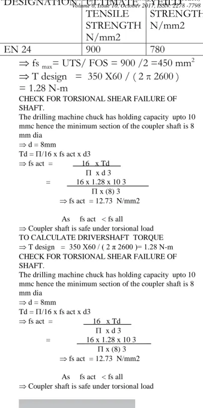
Fig.3.2 Equivalent Stresses
Fig 3.3 Total Deformation
Design of Flexible Shaft
TO CALCULATE FLEXISHAFT TORQUE
fs
max= UTS/ FOS = 900 /2 =450 N/mm
2T design = 350 X60 / ( 2 π 2600 )= 1.28 N-m
CHECK FOR TORSIONAL SHEAR FAILURE OF SHAFT.
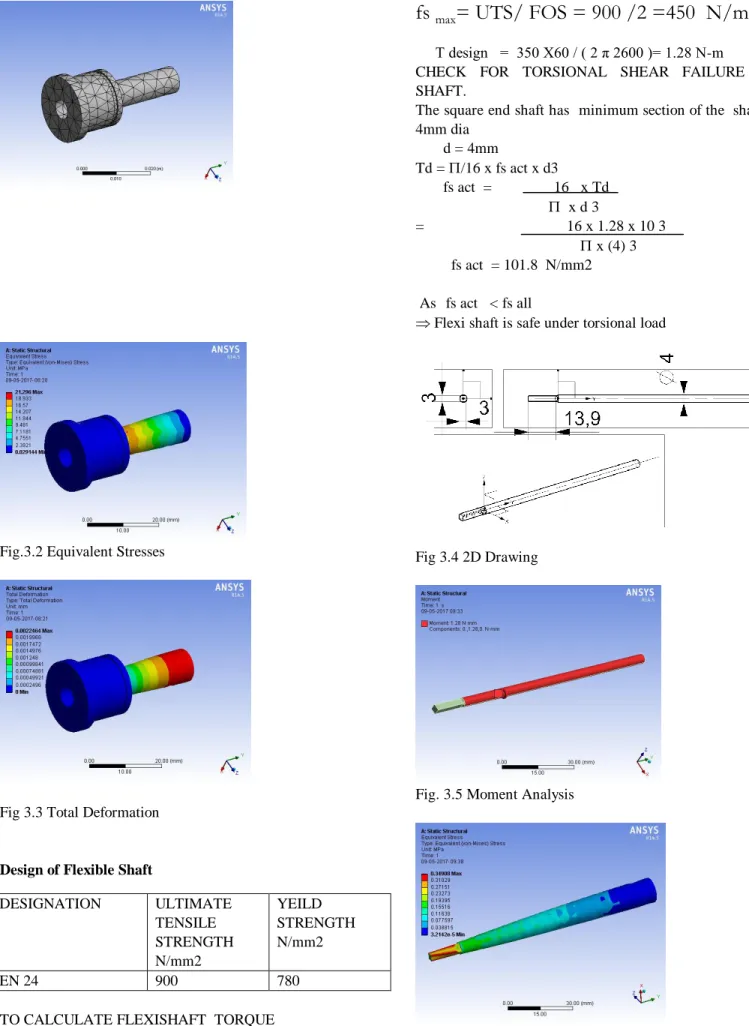
The square end shaft has minimum section of the shaft is 4mm dia d = 4mm Td = /16 x fs act x d3 fs act = 16 x Td x d 3 = 16 x 1.28 x 10 3 x (4) 3 fs act = 101.8 N/mm2 As fs act < fs all
Flexi shaft is safe under torsional load
Fig 3.4 2D Drawing
Fig. 3.5 Moment Analysis
DESIGNATION ULTIMATE TENSILE STRENGTH N/mm2 YEILD STRENGTH N/mm2 EN 24 900 780
Fig3.5 Equivalent Stresses
Fig 3.6 Total Deformation
Design of Elliptical Leaf Spring Material Selection
Top plate is subjected to direct compressive load under action the of weight of engine and accessories which is not to exceed 4 kg
Hence the load on LEAF = Total load/ No of LEAFS No of LEAFS = 2 ---(LEFT AND RIGHT included) Hence load on top plate = 2kg = 19.6N
Direct Tensile or Compressive stress due to an axial load :-
fc act =
fc act = 0.006 N/mm2
As fc act < fc all leaf spring is safe in compression
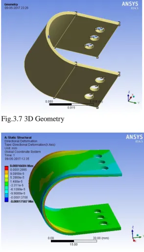
Fig.3.7 3D Geometry
Fig. 3.8 Directional Deformation X Axis
Fig. 6.9 Equivalent Stresses
Conclusion
This concept leads to reduce fatigue of worker during drilling on roof, ceiling. This is also reducing hand arm vibrations, vibrations are absorbed by vibration isolator. This increases comfort of worker. A flexible shaft is a very effective and cost efficient way to transmit rotary motion, power or torque. Flexible shafts are made with wire spiralled tightly around a central wire. With each layer you increase the diameter of the shaft and with that
DESIGNATION TEXTILE STRENGTH N/mm2 YEILD STRENGTH N/mm2 AISI 1095 SPRING STEEL 980 860 W 95 X 40 -
6
[(/4) 62]}
International Journal of Science, Engineering and Technology Research (IJSETR) Volume 6, Issue 10, October 2017, ISSN: 2278 -7798
1392
All Rights Reserved © 2017 IJSETR
the torque it can transmit. Radius can be reduced; the torsional deflection will go up, which for remote control cable is not a good thing. Related to this basic “reality” of flexible shafts, two main design groups emerge. First there are torque-Dtransmission shafts, mainly for higher speed, continuous speed, pure torque transmission applications like speedometer cable or shafts for drilling applications. Second are the torsion stable flexible shafts for mechanically remote applications, with low speed and focus n low torsional deflection. An example is slide adjustments for stationary cutting machines. Also there are special cables like flocked shafts, hollow shafts, shafts with helix wire and so on. Figure shows some examples of special flexible shafts. Direct influences on flexible shaft specifications are: the number of layers, the number of wires-per-layer, the diameter of the wire, the wire material (with higher or lesser carbon, different tensile strengths, different plating)
ACKNOWLEDGMENT
I wish to express my appreciation and gratefulness for the most cooperative attitude of Prof. K.P. Kolhe for their guidance thoughtful suggestions and the constant moral support I also thankful to Principal Dr. , Head of the Mechanical Department Prof. Biradar
REFERENCES
[1] KMyashita,SShiomi, N Itoh, T Kasmatsu, and H Iwata
Epidemiological study of vibration syndrome in response to total hand-tool operating time-British Journal of Industrial Medicine 1983;40:92-98
[2] M. J. Griffin (Auth.)-Handbook of Human Vibration-Academic Press (1990) Ch- 13-19.
[3] Douglous P Taylor “Fluid Dampers for Application of seismic energy dissipation and seismic isolation. Paper No.798;2-6
[4] S.A.Adewuisi, S.Rakeja,P. Marcotte, P.E. boileu “International Jurnal of industrial ergonomicsOn The descripancies in the reported human hand-arm impedance at higher frequencies. ”
2008; 38;703-714
[5] Martin E. Cobern, Ph.D., Director of New Product Development & Mark E. Wassell†, Manager of Analysis APS Technology, Inc. 800 Corporate Row Cromwell, CT 06416, USA “Drilling Vibration Monitoring And Control System” 2011;
32; 36-68
[6] S. Adewusi, S. Rakheja, P. Marcotte Biomechanical Model of the Hand-Arm System to Simulate Distributed Biodynamic Responses, Third American Conference of Human Vibration,2010; 6;1-4. [7] Biomechanical Model of the Hand-Arm System to Simulate Distributed
Biodynamic Responses “Epidemiological study of vibration syndrome in response to total hand-tool operating time”British Journal of Industrial Medicine 1983;40:92-98
[8] Li, K.W. Ergonomic evaluation of a fixture used for power driven wire‐ tyring hand tools. International Journal of Industrial Ergonomics, 2003; 32: 71‐79.
[9] Christopher W. Nicolay, Anna L Walker “Grip Strength and Endurance: Influence of anthropometric variation, Hand Dominance and Gender” – International journal of human ergonomics (2005) 35;605-618