R E S E A R C H
Open Access
Infrared stripe correction algorithm based
on wavelet decomposition and total
variation-guided filtering
Ende Wang
1,2, Ping Jiang
1,2,3*, Xuepeng Li
1,2and Hui Cao
1,2Abstract
Stripe non-uniformity severely affects the quality of infrared images. It is challenging to remove stripe noise in low-texture images without blurring the details. We propose a single-frame image stripe correction algorithm that removes infrared noise while preserving image details. Firstly, wavelet transform is used for multi-scale analysis of the image. At the same time, Total variation model is used for small window to smooth the original image. The small-scale total variation model can well preserve the edge information of the image, but it will leave stripe noise. Therefore, according to the prior knowledge of the vertical component of the stripe noise, the spatial filtering is finally performed: the smoothed image is used as the guide image for the stripe noise denoising. It is possible to prevent the lead filter from mistaking the strong stripe noise as edge detail, resulting in corrected image residual streak noise. The algorithm is systematically evaluated by experiments on simulated images and original infrared images, as well as compared with the current advanced infrared stripe non-uniformity correction algorithms. It is proved that our algorithm can better eliminate stripe noise and preserve edge details.
Keywords:Focal-plane array;non-uniformity correction, Infrared image, Multi-scale, Destriping
Introduction
Infrared imaging technology has a wide range of applica-tions in the industrial, military, and medical fields. Within infrared technology, the so-called infrared focal plane array (IRFPA) constitutes the core of infrared imaging systems, and possesses advantageous character-istics such as small size, low production cost, and high sensitivity [1]. IRFPA typically consist of a detector array and readout circuitry. However, owing to component mismatch and changes in parameters during the manu-facturing process, the pixel spatial response and the bias voltage of the readout circuitry are different. The result-ing infrared images suffer from severe spatial domain fixed pattern noise (FPN) that reduces their quality [2, 3]. Stripe non-uniformity is a special FPN caused by the non-uniformity of the amplifier in the readout circuitry.
In the field of image vision, a large number of non-uniformity corrected (NUC) algorithms have been pro-posed, but the NUC algorithm that preserves the edge details of the image while removing stripe noise is still a problem. The key problem is mainly to separate the stripe noise and high-frequency components, which is difficult due to the mixing and overlapping between there. The bilateral filter distinguishes edges and noise by setting thresholds to achieve edge retention [4–6]. However, it adapts to infrared images whose edges are more prominent than noise, and is not suitable for im-ages with low texture and strong noise [7, 8]. Cao et al. put forward the wavelet stripe correction algorithm, which decomposes the image in three levels of size and filters at each level of size. The algorithm is complex, and the effect of stripe noise is not ideal [1].. Qian [9] proposed the minimum mean square error striping method to extract the parameter information in the image for correction, which solves the convergence problem of the algorithm well and has a good de-striping effect, but there is the problem of losing the details of the image edge. The method proposed in
© The Author(s). 2019Open AccessThis article is distributed under the terms of the Creative Commons Attribution 4.0 International License (http://creativecommons.org/licenses/by/4.0/), which permits unrestricted use, distribution, and reproduction in any medium, provided you give appropriate credit to the original author(s) and the source, provide a link to the Creative Commons license, and indicate if changes were made.
* Correspondence:[email protected]
1Shenyang institute of automation, Chinese Academy of Sciences, 114, Nanta
Street, Shenhe District, Shenyang 110016, Liaoning, China
2Key Laboratory of Optical Electrical Image Processing, Chinese Academy of
Sciences, 114, Nanta Street, Shenhe District, Shenyang 110016, Liaoning, China
literature [10, 11] uses the prior knowledge of the struc-ture of the readout circuit to group the pixels, and ap-plies the correction model to normalize the pixels so that the pixels of the same group have similar outputs. However, the de-striping effect of the algorithm is not good, and the image residual has large stripe noise. Ten-dero et al. [12, 13] proposed an midway histogram equalization algorithm, which can effectively remove stripe noise, but there will be problems of missing image details, resulting in image blur. Moreover, the algorithm involves inverse histogram computations, so the compu-tational complexity is not suitable for real-time process-ing of images.
The purpose of our research is to propose a single-frame image processing algorithm, which can achieve stripe non-uniformity correction from the first frame without losing the edge information. The proposed algo-rithm mainly consists of three parts. Firstly, the image processing algorithm based on wavelet decomposition extracts the high-frequency components of the image, and decomposes the high-frequency components into vertical components, horizontal components and diag-onal components. At the same time, the original image is smoothed by small-scale using the total variation algo-rithm. The small scale total variation algorithm can keep the edge information of the image well, but it will leave stripe noise. Since stripe noise is caused by the fact that each column of infrared detector readout circuit shares the same amplifier, and the non-uniformity between am-plifiers leads to the formation of fixed stripe noise in the image, according to prior knowledge, stripe noise mainly exists in the vertical component [1]. In the spatial filter-ing step: the vertical component is taken as an input image, and the smoothed image is used as a guide image for stripe noise denoising. It can prevent the strong stripe noise from being mistaken for the edge detail by the guided filter and lead to the residual stripe noise in the corrected image. The proposed algorithm can elim-inate the stripe noise directly in the component part and simultaneously retaining image details.
Compared with other excellent NUC algorithms
[14–17], the proposed algorithm has two advantages.
First, it does not need to deal with multiple frames of images to cause unnecessary fuzzy problem. Secondly, the proposed algorithm can effectively remove the stripe noise of the image without blurring the details of the image.
This paper is organized as follows: In Section 2, the existing NUC algorithm and the mainstream image denoising algorithm is reviewed. In Section 3, a new in-frared image stripe correction approach is proposed. Section 4 describes the implementation details of the al-gorithm. Section 5 presents experimental results. Finally, the conclusion is drawn in section 6.
Related work
This paper reviews recent advances in FPN correction, including traditional NUC methods and specific correc-tion methods for single-frame image stripe non-uniformity.
Traditional NUC algorithms are included within two major categories, namely calibration-based methods
[18–20] and scene-based methods [21–24]. Algorithms
within the first category are simple. They employ the two-point calibration method as a classic calibration al-gorithm. A surface source black body is used to provide a reference temperature to calibrate the detector re-sponse by measuring two different known radiations. However, this method increases the complexity and power consumption of the infrared imaging system, and cannot achieve real-time correction of the system. The second category encompasses several common strategies such as constant statistical methods, filtering estimation methods, and image registration methods. In general, these scene-based NUC methods perform stripe noise correction of the image by reasonably estimating the model parameters. However, the limitation of this scene algorithm is that it requires multiple frames of images to obtain a stable correction factor, which requires a large amount of hardware resources to be consumed in actual engineering. Furthermore, the scene-based NUC algo-rithm requires images to have sufficient scene motion. Otherwise, it will cause blurring of the edge of the target object in the image.
problem naturally. Kuang et al. [33] proposed a deep convolutional neural network (CNN) model to correct the non-uniformity in a single-frame infrared image, which remove stripe noise effect is better.
NUC algorithm based on multi-scale analysis and total variation-guided filtering
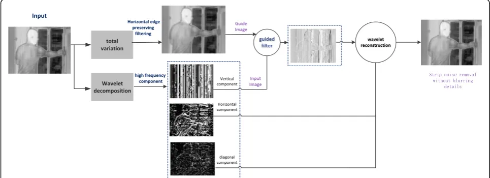
The proposed algorithm is mainly composed of three parts: (1) The high frequency components of the original image are extracted, and a wavelet transform is applied to decompose the vertical component containing the stripe noise. (2) The raw infrared image is small-scale gradient equalization by total variation model to elimin-ate strong noise. (3) The smoothed image is used as the guide image, and the vertical component including the stripe noise is used as an input for denoising before the finally wavelet reconstruction is performed. The complete processing flow is shown in Fig.1.
Wavelet transform image multi-scale decomposition Wavelet analysis technology can unfold the image hier-archically according to the wavelet base, and can deter-mine which level to expand to according to the nature of the image and the image processing requirements given in advance, so that not only can the amount of cal-culation be effectively controlled, but also the image can be satisfied real-time processing requirements [34–36] . The wavelet transform separates the original image from different resolution details with different scales [37].. Therefore, this paper uses wavelet decomposition to rep-resent different directions of the image.
The wavelet transform decomposes the original image
Y(i) into high-frequency components F(i) and approxi-mate componentsX(i), and its formula is expressed as:
Y ið Þ ¼X ið Þ þF ið Þ ¼X ið Þ þN ið Þ þV ið Þ ð1Þ
The high frequency component F(i) includes stripe noiseN(i) and vertical texture informationV(i) [38]. The high-frequency component F(i) is decomposed by wave-let and can be expressed by the formula:
Fð Þ ¼i fHi;Vi;Dig ð2Þ
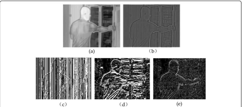
whereHithe horizontal component,Vithe vertical com-ponent, and Di the diagonal component. The result of the image after wavelet transform can be clearly ob-served as shown in Fig.2. As shown in Fig.2b, the stripe noise is basically present in the high frequency compo-nents of the image, and the high frequency component is further decomposed by wavelet, as shown in Fig.2c-e, stripe noise exists in the vertical portion of the high fre-quency component. According to this experimental con-clusion, we eliminate the stripe noise in the vertical component. The following sections will give a detailed description.
Total variation small-scale image smoothing [29,31] The idea of using total variation denoising is to trans-form the image denoising problem into an image func-tional energy minimization problem. By adjusting the fidelity and regular terms of the total variation model, the image denoising is realized. The total variation model is shown in formula3:
λH uð ÞTV−L1¼
Z
Ω
k1juxj þk2juyj
ð3Þ
Where k1 and k2 represent the balance factor, Since the infrared fringe noise mainly affects the horizontal gradient of the image, uy is replaced by (u−f)y on the
Fig. 1Algorithm flowchart. This single frame based stripe correction method effectively removes stripe non-uniformity without blurring detail
basis of the original model. The total variational model suitable for infrared stripe noise is shown in formula 4:
λH uð ÞTV−L1¼
Z
Ω
λ1juxj þλ2jðu−fÞyj
ð4Þ
The functional energy equation obtained is:
E uð Þ ¼ minλ1k kux 1þλ2ðu−fÞy1þ 1 2ðu−fÞ
2 ð
5Þ
The size of the image is a two-dimensional matrix of M × N size, and a stepwise information of the horizontal direction and the vertical direction is expressed by:
juxj¼ fjuiþ1;j−ui;jj if i∠M
0 if i¼M ð6Þ
jðu−fÞyj
¼ juiþ1;j−ui;jj− fi;jþ1−fi;j
if j∠N
0 if j¼N
( )
ð7Þ
Formula6 and formula7 are substituted into formula 5 to obtain the discrete numerical expression of the stripe-noise removal model with total variation:
E uð Þ ¼X M
i¼1
XN
j¼1
jλ1 uiþ1;j−ui;j
þλ2 uiþ1;j−ui;j
−fi;jþ1−fi;j
h i
j þ1
2
XM
i¼1
XN
j¼1
ui;j−fi;j
2
ð8Þ
In formula 4, dx=ux, dy=uy, and the sum is usually equal to 0.01. Through Lagrange multiplier method, auxiliary variables bx and by are introduced to convert eq.9into an unconstrained equation foization.
minλ1k kdx 1þλ2 dy 1þ 1 2ku−fk
2 2
þA
2kdx−ux−bxk 2 2þ
B
2 dy−ðu−fÞy−by
2
2 ð9Þ
Aand Bare the penalty coefficients of the equation,bx is the auxiliary variable in the x-axis direction, and byis the auxiliary variable in the y-axis direction. In the spe-cific solution, the parameters in the equation are sepa-rated, and the contraction operator λ is introduced to solve the auxiliary variablesbxand by.The effect of total variation smoothing in this section is to prevent the leading filter from mistakenly saving the stripe noise with large amplitude as edge structure. However, the total variation smoothing also needs to control the edge information of the image to prevent the guiding filter from deleting the texture information as noise. Figure3 shows the effect of the equilibrium coefficients k (k1and k2) on the experiment when they are chosen to be 0.01,
Fig. 2Wavelet decomposition:aoriginal picture,bHigh frequency component.cvertical component,dhorizontal component, and (e)
0.08, and 0.20. It can be seen from the experiment that the larger the balance coefficient, the more serious the edge details of image loss. Therefore, the equilibrium co-efficients k1 and k2 we selected in the experiment are 0.01.
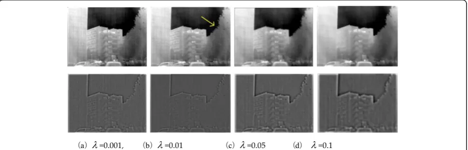
Figure 4 shows the smooth result of selecting λ as 0.001, 0.01, 0.05 and 0.1, respectively. Firstly,λ selects a very small value, the image will leave a lot of stripe noise (as shown in Fig. 4a). When λ selects a relatively large value (λ = 0.05 or 0.1), the image will blur the vertical edge detail of the image (as shown in Fig. 4c and d. Therefore, the experiment selects λ =0.01, the image smoothes the strong stripe noise of the image, and saves the edge detail information of the image.
Guide filtering removes stripe noise
Guided filter was first proposed by He [39] and has been widely used in image denoising and image defogging. The initial image p (input image) is sub-jected to filtering processing by a guide picture g such that the final output image q is substantially similar to the initial image P, but the texture portion is simi-lar to the guide picture g. The formula defined be-tween the two is as follows [5, 39]:
qi¼akgiþbk;∀i∈wk ð10Þ
whereakand bkare the linear coefficient and bias co-efficient in windowwk,iandkare pixel indexes,gis the guide picture, wk is the window with radius h, and the constraint equation of ak and bk in window wk can be expressed as:
E akð ;bkÞ ¼X i∈wk
akgiþbk−pi
2
þεak2
ð11Þ
Whereεis the regularization parameter, and is used to makeakconverge.
By solving the least squares (squares) method, the minimum deviation between the reference image and the corrected image can be obtained. The coefficientsak andbkare:
ak ¼ 1
jwj
X
i∈wk
pigi−pkuk
σ2 kþε
ð12Þ
bk¼pk−akuk; ð13Þ
Where, uk and σ2k are the mean and variance of the
guidance image g in window wk, pk is the mean of the
Fig. 3The original image using differentk(k1andk2)values for total variational smoothing
Fig. 4Top: The original image using differentλvalues for total variational smoothing. Bottom:Correcting image high frequency components . In
input imagepin window wk, and∣w∣is the number of pixels in windowwk.
It can be seen from the above review that if the parameterization value is normalized, the value of the guided filter windowhwill determine the output quality of the image, where H represents the height of the raw image. Figure 5 shows the calibration results using dif-ferent filter values. We seth= 0.1H,h= 0.3H,h= 0.5H, and h = 0.7H, respectively. It is clear from the experi-mental results that h uses a small window size (h = 0.1H). The corrected image will have residual stripe noise, as shown in Fig. 5b. When h uses a larger value (h = 0.5H or h = 0.7H), as shown in Fig. 5d and the highlighted portion in Fig. 5e, the result is noticeable blurring of image detail. When set to h= 0.3H, the cor-rection effect is better, stripe noise is eliminated and edge detail information is retained,as shown in Fig.5c In the experiment of this paper, we set h= 0.3H and the regularization parameterε= 0.22.
Implementation details
In this section, we explain the precautions of the algo-rithm. First, the considerations of wavelet transform、 -total variation smoothing and guiding filter are described in detail, and then the implementation process of the whole algorithm is taken as a reference.
Detail description
For M × N size images (M and N are even by default), the original image is decomposed by the db1 wavelet base and the size becomes half of the raw image.. When the original image is subjected to total variation smooth-ing, in order to avoid the loss of image details, and the
contraction operatorλ used is 0.01. In the spatial filter-ing process of the image, the output image of the total variation smoothed is used as the guided image, and the vertical component after wavelet decomposition is used as the input image of the guided filter. We set regularization parameter ε is 0.22 [5], and guiding filter window size is selected a small value to avoid blurring edges of the image. In the experiment, We seth= 0.3H.
Procedure
The pseudoalgorithm for our proposed is presented as Algorithm.
Experiment and analysis
We test the algorithm on raw infrared image, and give quantitative comparison, qualitative analysis and param-eter discussion. In the experiment, three state-of-the-art stripe removal methods were compared, namely midway histogram equalization (MHE) [13], L-model algorithm
Fig. 5Stripe correction results for different filter window heights.Hrepresents the height of the raw image. The regularization parameterεis set
[10] and CNN [33]. All parameter variables of these comparison algorithms are set to the default values using the corresponding references. We also add the conven-tional image filtering method (Guide Filtering Algorithm (GIF) [18] and Gaussian filter) to compare, further illustrate the denoising ability of the algorithm.
Data set
We validated our proposed algorithm using real infrared images from public data sets, as shown in Fig. 6. The data set is available under the Creative Commons Attri-bution (CC-BY) license [13], and we selected 3 frames of infrared images with streak noise.
Test on raw infrared images
We choose two types of correction algorithms for ex-perimental comparison. One is the filtering algorithm commonly used in image processing (guided filtering with edge structure holding capability [5, 39] and com-monly used image smoothing filters). The other type is a number of state-of-the-art stripe correction algorithm, including L-model algorithm [10], midway histogram equalization algorithm [13] and CNN [33]. Experiments with real infrared images further illustrate the de-striping performance of the proposed algorithm.
Comparison with common filtering algorithms
We compare the two common smoothing filters with our proposed method. It is applied to the selection of in-frared images with weak edge structure information and severe stripe noise [12]. The comparison algorithm includes guided filtering and 1D Gaussian filtering. .
In the experiment, the smoothing parameter of the Gaussian filter is set toγ=0.4, we also set filter window of the Gaussian filter is 2. The regularization parameter εof the guided filtering is set to 0.22and the guided fil-tering window is set to h= 0.3H. For proposed method, the wavelet basis function of the wavelet transform is set to db1, the contraction factorλof total variational small window smoothing is set as 0.001, the regularization parameter εof guided filtering and denoising is also set as 0.22, and the filtering window h= 0.3H. The experi-mental results are shown in Fig.7. Gaussian filtering can basically eliminate all the infrared stripe noise, but in es-sence, Gaussian filtering convolves the entire frame image, and does not distinguish the edge information and the stripe noise, resulting in blurring of the image edge information. Guided filtering has a better de-striping effect, but since the guided filtering also denoises the entire frame image, it also causes a small amount of texture information to be lost, and cannot
Fig. 6Three infrared images for experimental testing.aScene named is suitcase [13];bScene named is leaves [13];cScene named is
people [13]
Fig. 7Top: raw infrared image and strip noise removal results using filtering algorithms and our proposed method. Bottom: Zoom-in views on
simultaneously balance the stripe noise and texture in-formation, especially for weakly textured images. A lot of image detail will be lost. The proposed method can effective eliminates stripe noise while preserving edge detail.
Comparison test of stripe non-uniformity correction algorithm
In the specific implementation, we use three sets of scenes and different noise image sequences. We choose three non-uniform stripe correction algorithms to com-pare with the proposed algorithm, including L-model
algorithm [10], midway histogram equalization algorithm (MHE) [13] and CNN [33]. The MHE algorithm by tak-ing the midway histogram process, the smoothtak-ing be-tween columns is achieved,complete the process of removing the stripe noise of the infrared image. The L-model algorithm uses the prior knowledge of the read-out circuit structure to group the pixels and apply the correction model to normalize the pixels so that the same set of pixels have similar outputs. The CNN algo-rithm introduces the neural network method into the field of infrared image processing to solve the traditional stripe noise problem.
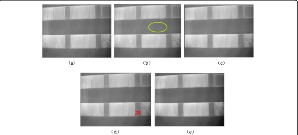
Fig. 8Multiple stripe non-uniformity correction algorithm processing results for people.aRaw;bL-model;cCNN;dMHE;eOurs
The original image and the image after NUC are shown in Fig. 8, 9and 10. Observing the image, we can find that there are a lot of stripe noise in the original image, and the three correction algorithms can effect-ively correct the stripe noise. However, the L-model al-gorithm does not produce satisfactory noise reduction effect. A large number of strips are still visible in their processing results. (as shown in the yellow highlight area). The MHE algorithm removes non-uniform stripe noise better, but the image is too smooth, it still loses a certain amount of image detail. (as indicated by the red arrow). The image corrected by the CNN algorithm has
a milder visual effect, but there is also a loss problem for the image weak texture information. The proposed algo-rithm has better stripe noise effect without introducing troublesome fuzzy problems, and preserves most of the edge structure information of the image.
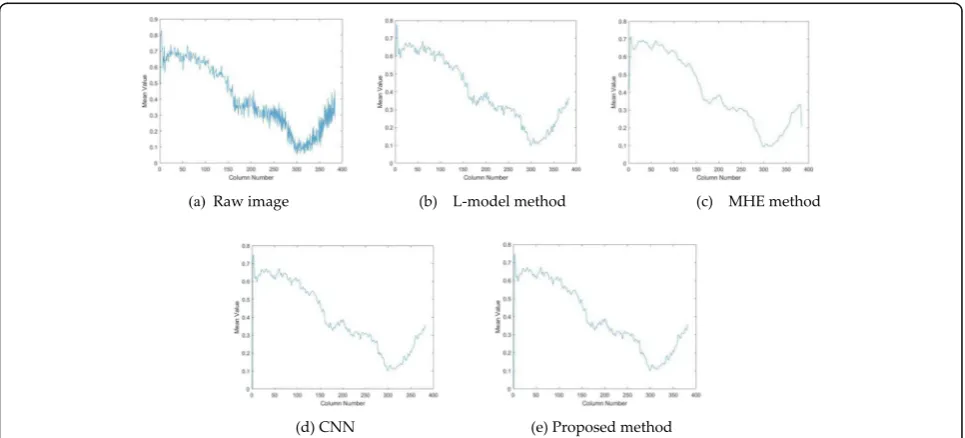
We calculated the mean cross-track profiles of the ori-ginal image and the algorithm-corrected image, and ex-plained it by quantitative analysis. The result is shown in
Fig. 11.The effect of stripe non-uniformity can be seen
as a rapid change between column mean values. Figure 11a is the column mean curve of Fig. 8a. After the L-model algorithm is corrected (Fig.11b), these
Fig. 10Multiple stripe non-uniformity correction algorithm processing results for suitcase.aRaw;bL-model;cCNN;dMHE;eOurs
changes are reduced, However, There are still some small fluctuations from the curve, indicating uncorrected re-sidual non-uniformity. The MHE algorithm (Fig.11c) sub-stantially eliminates these small fluctuations. However, it can be seen that the curve is too smooth, indicating that changes in image detail are also lost due to excessive smoothness. The algorithm proposed in this paper (Fig.11e) and the CNN (Fig.11d) algorithm have similar curves, which smooth the stripe noise while maintaining small mean changes corresponding to the image details.
To further prove above findings, we applied image quality metrics, Peak Signal-to-Noise Ratio (PSNR) and Structural Similarity Index (SSIM) [29], to evaluate the de-striping performance of the algorithm. PSNR can rep-resent the pixel error between the corrected image and the input image, and the higher the PSNR value, the smaller the distortion of the image. The closer the image is to the original image. The formula is defined as:
PSNR¼10 log10255 2
MSE ð14Þ
where MSE represents the expected value of the mean square error between the corrected image and the input image.
SSIM theory holds that natural image signals are highly structured, that is, there is a strong correlation between pixels, especially the closest pixels in the spatial domain. This correlation implies important information about the structure of objects in the visual scene, The formula is defined as:
SSIM Eð ;FÞ ¼ ð2μEμFþp1Þð2σEFþp2Þ μ2
Eþμ2F þp1
σ2
Eþσ2Fþp2
ð15Þ
whereEandFrepresent the image blocks extracted from the corrected image and raw image by sliding window, and σE, σF, μE, μF, σEF represent the standard deviation, mean value and cross-correlation of E and F. p1and p2
take constants is to avoid errors where the denominator is zero in the arithmetic division..In the experimental meas-urement results, The maximum value of SSIM is 1.The closer to 1 the better the effect of maintaining the edge structure information of the corrected image [36].
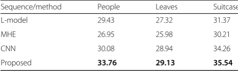
Table 1 and Table 2 calculate the PSNR value and SSIM value of several methods, which are contains dif-ferent stripe noise intensities. As can be seen from all experiments, As can be seen from the table, the PSNR value and the SSIM value obtained by the proposed method are the highest., which indicates the de-striping performance of the proposed algorithm.
Time consumption
We calculated the running time of several stripe corrected methods. The experimental environment was Matlab 2017a, Intel Core i7 CPU and 8GB RAM. The statistical results are shown in Table 3. The proposed method requires a minimum of time compared to several other algorithms. As the resolution of the scene increases, the runtime required by the proposed algorithm is sub-stantially stable at a lower level, which means that our algorithm is likely to be applied to hardware circuitry.
Results and discussion
Stripe non-uniformity has its own characteristics, and it can be seen that the significantly different between columns and columns and extend throughout the overall image. There is no noise-like pattern in other features such as shape com-pared to objects. The stripe noise is basically present in the high-frequency components of the image [36]. This paper performs multi-scale representation of the image and de-composes the vertical component of the image. Therefore, the idea of the algorithm is to process and de-noise the verti-cal component of the original image, To achieve the de-striping effect and preserve the details of the image. .
The general idea of the algorithm can be shown in Fig.12. The high frequency of the image is shown in Fig.12b. The stripe noise is concentrated in the high frequency Table 1PSNR (dB) values of correction algorithms under
different scenarios
Sequence/method People Leaves Suitcase
L-model 29.43 27.32 31.37
MHE 26.95 25.98 30.21
CNN 30.08 28.94 34.26
Proposed 33.76 29.13 35.54
Entires in boldface are the proposed algorithm correction results
Table 2SSIM values of correction algorithms under different scenarios
Sequence/method People Leaves Suitcase
L-model 0.916 0.839 0.842
MHE 0.923 0.821 0.828
CNN 0.948 0.817 0.604
Proposed 0.969 0.942 0.929
Entires in boldface are the proposed algorithm correction results
Table 3Computing time (s) of different corrected methods for raw infrared images
Sequence/method People Leaves Suitcase
Resolution 640 × 480 640× 440 320 × 220
L-model 0.072 0.068 0.036
MHE 0.059 0.051 0.021
CNN 1.642 1.634 1.028
Proposed 0.048 0.036 0.018
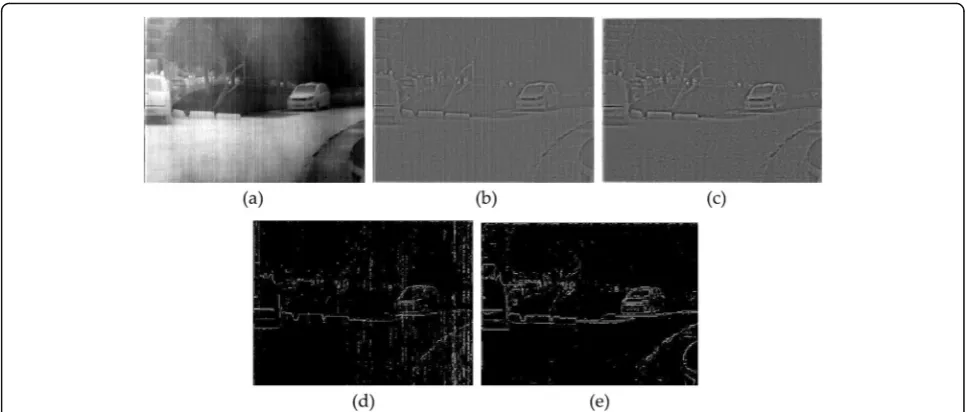
component. After the algorithm is corrected, the stripe noise is eliminated and the image detail information is retained (as showen in Fig.12c). We further demonstrate the perform-ance of the proposed algorithm by the edge detection oper-ator of the image. As shown in Fig.12d, the extracted edge operator has obvious noise, which will greatly affect the sub-sequent processing of the image. After the correction algo-rithm of this paper, the edge extracted as shown in Fig.12e has obvious improvement. Prove the application value of the algorithm.
Conclusion
In this work, an effective method to correct for stripe non-uniformity while preserving edges and image tex-tures is presented. The advantage of the algorithm is that multi-scale representation of the image by wavelet transform, and the edge preserving smoothing of the image by introducing total variational method, which avoids the retention of strong noise as detail information in the processing of the algorithm. It ensures that no image details will be lost in the denoising process. Fi-nally, guided filter is used for denoising, and the experi-ments show that the algorithm can remove the stripe noise and keep the edge details of the image.
Abbreviations
CNN:Convolutional Neural Network; FPN: Fixed Pattern Noise; GIF: Guide Filtering Algorithm; IRFPA: Infrared focal plane array; MHE: Midway Histogram Equalization; NUC: Non-Uniform Correction; PSNR: Peak Signal-to-Noise Ratio; SSIM: Structural Similarity
Acknowledgments
We thank the reviewers for helping us to improve this paper. This work is supported by the Equipment pre-research field fund of China (No. 61404150302).
Authors’contributions
All authors contributed equally in compiling this review. All authors read and approved the final manuscript.
Funding
Shenyang Institute of Automation, Chinese Academy of Sciences provides the funding for this research.
Availability of data and materials
Upon request to the authors
Competing interests
The authors declare that they have no competing interests.
Author details
1Shenyang institute of automation, Chinese Academy of Sciences, 114, Nanta
Street, Shenhe District, Shenyang 110016, Liaoning, China.2Key Laboratory of Optical Electrical Image Processing, Chinese Academy of Sciences, 114, Nanta Street, Shenhe District, Shenyang 110016, Liaoning, China.3College of automation and Electrical Engineering, Shenyang Ligong University, NO. 6 Nanping Middle Road, Hunnan District, Shenyang 110159, Liaoning, China.
Received: 6 August 2019 Accepted: 13 December 2019
References
1. Cao, Y., He, Z., Yang, J., Ye, X., Cao, Y.: A multi-scale non-uniformity correction method based on wavelet decomposition and guided filtering for uncooled long wave infrared camera. Signal processing. Image Commun.60, 13–21 (2018)
2. Zuo, C., Chen, Q., Gu, G., Sui, X.: Scene-based nonuniformity correction algorithm based on interframe registration. JOSA A.28, 1164–1176 (2011) 3. Cao, Y., He, Z., Yang, J., Cao, Y.: Spatially adaptive column fixed-pattern noise
correction in infrared imaging system using 1D horizontal differential statistics. IEEE Photonics J.9, 1–13 (2017)
4. Tomasi, C., Manduchi, R.: Bilateral filtering for gray and color images. In: Proceedings of the 6th International Conference on Computer Vision Freiburg, Germany, 2–6 June, pp. 839–846 (1998)
5. He, K., Sun, J., Tang, X.: Guided image filtering. In:Computer Vision–ECCV, pp. 1–14. Springer, Berlin/Heidelberg (2010)
6. Kou, F., Chen, W., Wen, C., Li, Z.: Gradient domain guided image filtering. IEEE Trans. Image Process.24, 4528–4539 (2015)
Fig. 12High frequency and edge contour of the image (a) raw; (b) raw image high frequency; (c) correction image high frequency; (d) raw
7. Morris, N., J., W., Avidan, S., et al.: Statistics of infrared images. Computer Vision and Pattern Recognition (CVPR), pp. 1–7. (2007).
8. Sui, X., Chen, Q., Gu, G.: Algorithm for eliminating stripe noise in infrared image. J. Infrared Millim. Waves.31, 106–112 (2012)
9. Qian, W., Chen, Q., Gu, G.: Minimum mean square error method for stripe nonuniformity correction. Chin. Opt. Lett.9, 34–36 (2011)
10. Narayanan, B., Hardie, R.C., Muse, R.A.: Scene-based nonuniformity correction technique that exploits knowledge of the focal-plane array readout architecture. Appl. Optics.44, 3482–3491 (2015)
11. Hogasten, N., et al.: Systems and Methods for Processing Infrared Images: Jun. 26 , US Patent 8,208,026 (2018)
12. Tendero, Y., Landeau, S., Gilles, J.: Non-uniformity correction of infrared images by midway equalization. Image Process. Line.2, 134–146 (2012) 13. Tendero, Y., Gilles, J.: ADMIRE: a locally adaptive single-image,
non-uniformity correction and denoising algorithm: application to uncooled IR camera. In: Infrared Technology and Applications XXXVIII, p. 83531. International Society for Optics and Photonics, Baltimore, 23–27 April (2012) 14. Buades,A.,Bartomeu,C., et al.: A non-local algorithm for image denoising.
Computer Vision and Pattern Recognition (CVPR), 2, 60–65 (2005). 15. Dabov, K., Foi, A., Katkovnik, V., et al.: Image denoising by sparse 3D
transform-domain collaborative filtering. IEEE Trans. Image Process.16, 2080–2095 (2007)
16. Qian, W., Chen, Q., Gu, G., Guan, Z.: Correction method for stripe nonuniformity. Appl. Optics.49, 1764–1773 (2010)
17. Zhao, F., Zhou, Q., Chen, Y., et al.: Single image stripe nonuniformity correction with gradient-constrained optimization model for infrared focal plane arrays. Opt. Commun.296, 47–52 (2013)
18. Wang, Y.M., et al.: Study on two-point multi-section IRFPA nonuniformity correction algorithm. J. Infrared Millim. Waves.22, 415–418 (2003) 19. Friedenberg, A., Goldblatt, I.: Nonuniformity two-point linear correction
errors in infrared focal plane arrays. Optim. Eng.37, 1251–1253 (1998) 20. Perry, D.L., et al.: Linear theory of nonuniformity correction in infrared
staring sensors. Optim. Eng.32, 1854–1859 (1993)
21. Pipa, D.R., da Silva, E.A.B., Pagliari, C.L., Diniz, P.S.R.: Recursive algorithms for bias and gain nonuniformity correction in infrared videos. IEEE Trans. Image Process.21, 4758–4769 (2012)
22. Maggioni, M., Sanchez-Monge, E., Foi, A.: Joint removal of random and fixed-pattern noise through spatiotemporal video filtering. IEEE Trans. Image Process.23, 4282–4296 (2014)
23. Harris, J.G., Chiang, Y.M.: Nonuniformity correction of infrared image sequences using the constant-statistics constraint. IEEE Trans. Image Process. 8, 1148–1151 (1999)
24. Hardie, R.C., Hayat, M.M., Armstrong, E., Yasuda, B.: Scene-based nonuniformity correction with video sequences and registration. Appl. Optics.39, 1241–1250 (2000)
25. Cao, Y., Yang, M.Y., Tisse, C.L.: Effective strip noise removal for low-textured infrared images based on 1-D guided filtering. IEEE Trans. Circuits Syst. Video Technol.26, 2176–2188 (2016)
26. Liu, L., Zhang, T.: Optics temperature-dependent nonuniformity correction via L0-regularized prior for airborne infrared imaging systems. IEEE
Photonics J.8, 1–10 (2016)
27. Li, D.H., Li, L.L., Liu, D.W.: Temperature dependence of the Raman spectra of Bi2Te3and Bi0.5Sb1.5Te3thermoelectric films. Phys. Status Solidi (RRL) - Rapid
Res. Lett.6(6), 268–270 (2012)
28. Sui, X., Chen, Q., Gu, G.: Adaptive grayscale adjustment-based stripe noise removal method of single image. Infrared Phys. Technol.60, 121–128 (2013) 29. Boutemedjet, A., Deng, C., Zhao, B.: Edge-aware unidirectional total variation
model for stripe non-uniformity correction. Sensors.18, 1164 (2018) 30. Xu, K.K.: Silicon MOS optoelectronic micro-Nano structure based on
reverse-biased PN junction. Phys. Status Solidi A.216(7), 1–9 (2019)
31. Huang, Y., He, C., Fang, H., Wang, X.: Iteratively reweighted unidirectional variational model for stripe non-uniformity correction. Infrared Phys. Technol.75, 107–116 (2016)
32. Chang, Y., Yan, L., Wu, T., Zhong, S.: Remote sensing image stripe noise removal: from image decomposition perspective. IEEE Trans. Geosci. Remote Sens.54, 7018–7703 (2016)
33. Kuang, X., Sui, X., Chen, Q., Gu, G.: Single infrared image stripe noise removal using deep convolutional networks. IEEE Photonics J.9, 1–13 (2017) 34. Pande-Chhetri, R., Abd-Elrahman, A.: De-striping hyperspectral imagery using
wavelet transform and adaptive frequency domain filtering. ISPRS J. Photogramm. Remote Sens.66, 620–636 (2011)
35. Gonzalez,R.C., et al.: Digital Image Processing. 3rd Edition, Prentice Hall, India. pp. 461–524 (2008).
36. Wang, E., Jiang, P., Hou, X., et al.: Infrared stripe correction algorithm based on wavelet analysis and gradient equalization. Appl. Sci.9(10), 1993–2011 (2019)
37. Lu, X.L., Liu, R., Liu, J., et al.: Removal of noise by wavelet method to generate high quality temporal data of terrestrial MODIS products. Photogramm. Eng. Remote Sens.73, 1129–1139 (2007)
38. Cao, Y.P., Li, Y.: Strip non-uniformity correction in uncooled long-wave infrared focal plane array based on noise source characterization. Opt. Commun.339, 236–242 (2015)
39. He, K., Sun, J., Tang, X.: Guided image filtering. IEEE Trans. Pattern Anal.35, 1397–1409 (2013)
Publisher’s Note

![Fig. 6 Three infrared images for experimental testing.people [ a Scene named is suitcase [13]; b Scene named is leaves [13]; c Scene named is13]](https://thumb-us.123doks.com/thumbv2/123dok_us/9617132.1943959/7.595.57.540.549.702/infrared-images-experimental-testing-people-scene-suitcase-scene.webp)