R E S E A R C H
Open Access
Development of multi-pitch tool path in
computer-controlled optical surfacing
processes
Jing Hou
1,2, Defeng Liao
1,2*and Hongxiang Wang
1Abstract
Background:Tool path in computer-controlled optical surfacing (CCOS) processes has a great effect on middle spatial frequency error in terms of residual ripples. Raster tool path of uniform path pitch is one of the mostly adopted paths, in which smaller path pitch is always desired for restraining residual ripple errors. However, too dense paths cause excessive material removal in lower removal regions deteriorating the form convergence. Methods:With this in view, we propose a novel tool path planning method named multi-pitch path. With the path, the material removal map is divided into several regions with varied path pitches according to the desired removal depth in each region. The path pitch is designed larger at low removal regions while smaller at high removal regions, and the feeding velocity of the tool is maintained at high level when scanning the whole surface. Results and conclusions:Experiments were conducted to demonstrate this novel tool path planning method, and the results indicate that it can successfully restrain the residual ripples, and meanwhile guarantee favorable convergent rate of form error.
Keywords:Multi-pitch tool path, Middle spatial frequency error, Residual ripple, Removal regions
Background
Large optics has been widely used in interferometers, tele-scopes, high-power lasers and other optical systems. In these systems, the optics are required of stringent specifica-tions of low, middle and high spatial frequency errors [1, 2]. Various CCOS processes have been developed which can provide good solutions for the fabrication of these optics because of their high convergence rates of low frequency error (i.e. surface form) [3–5]. Nowadays, more and more attentions have been paid to the middle spatial frequency (MSF) error, which is crucial for image performance and beam quality [6]. MSF error is primarily introduced during the CCOS processes, and it is hard to restrain. It is reported that MSF error is mainly affected by the initial surface error distribution (spatial and frequency domain), the removal function characters (profile, removal effi-ciency and stability) and the adopted paths [7, 8].
During CCOS, the tool is numerically controlled to traverse a path with a varied feeding velocity to obtain the desired removal map. The tool path plays an important role in the deterministic removal process, which has to cover the whole optic surface. There are several tool paths utilized in CCOS processes, such as the regular raster and spiral paths, and several kinds of random path [9–11]. The ran-dom path is claimed to be useful for reducing the MSF error, [12] but is hard to achieve a high precision surface form because of the difficulty in tool speed management [7]. The spiral and raster paths are more prone to generat-ing MSF error in terms of residual ripples due to their in-herent regular pattern. Spiral paths are suitable for circular optics as the tool is driven to traverse a radius while the optic mounted on a turntable rotates simultaneously [13].
Raster path is usually adopted for the fabrication of square-shaped optics. During polishing with raster path, the tool feeds along a straight line and then translates to another parallel line. This process is repeated to cover the whole surface. The pitch between adjacent path lines is commonly set identical (i.e. uniform pitch) on the whole surface, and the feeding velocity along each path * Correspondence:[email protected]
1School of Mechatronics Engineering, Harbin Institute of Technology, Harbin
150001, China
2Research Center of Laser Fusion, China Academy of Engineering Physics,
Mianyang 621900, China
uniform pitch path, the smallest removal region (lowest region) will commonly bring with such over-removal. Since, the decreased pitch is propitious to restraint of MSF errors [15]. On the other hand, the decreased pitch will greatly increase over-removal especially in the low-est region deteriorating the form correction precision. Hence, it is needed to develop an optimized tool path planning method which can solve this problem.
A novel tool path planning method named multi-pitch path, is developed in this paper. With this method, the material removal map is divided into several regions with varied path pitches according to the desired re-moval depth in each region. The path pitch is designed larger at low removal regions, so as to bring much less over-removal; while smaller at high removal regions, so as to decrease MSF error in terms of the residual ripples. The path has obvious advantage in restraint of residual ripples, and meanwhile can guarantee convergent rate of form errors. In the following section II, the correlation between the ripple and MSF error is analyzed to verify the rationality of characterizing the MSF error by rip-ples. In section III, the factors impacting ripple errors, including the removal amount and path pitch are dis-cussed. In section IV, the multi-pitch path and polishing procedure with the path are detailed and the experimen-tal validation is conducted.
Method
Verification of characterizing MSF errors with the residual ripple
Spatial frequency of surface errors is divided into several separate bands in the field of high power lasers [2]: sur-face figure (>33 mm), MSF error (0.12 ~ 33 mm) and
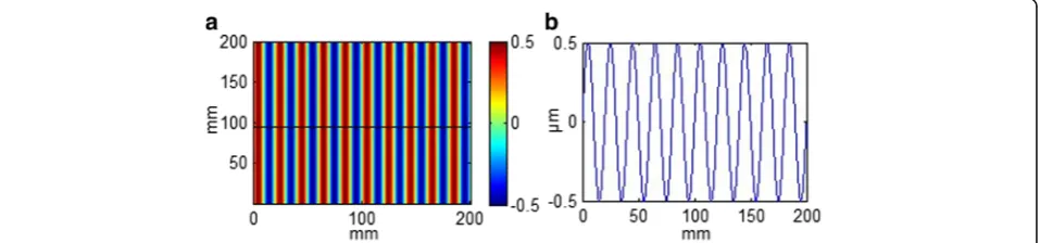
specify the correlation between residual ripple error and MSF error, we formulated a series of sinusoidal surface forms with variable spatial frequency and magnitude (see Fig. 1). The surface forms are sinusoidal distributed in xdirection, while are uniformly distributed in y dir-ection. Surface forms of this shape are fairly similar to the local regions of surface forms practically corrected by CCOS processes, which are nearly sinusoidally-distributed in the scanning direction while nearly uniformly-distributed in the feeding direction. Herein, the MSF error, in terms of the RMS value in the mid-spatial frequency band (0.0303 ~ 8.33 mm−1), is calcu-lated for all the surface forms as shown in Fig. 2. It is revealed that the spatial frequency has little effect on the RMS value, while there has a good linear relation-ship between the spatial magnitude and the RMS value. Thus, we should focus on the residual ripple magnitude rather than the frequency while restraining MSF errors.
Influencing factors of residual ripple errors
As revealed above that residual ripple error can be char-acterized by the ripple amplitude, i.e. the peak-to-valley value of the ripple (PVe). We introduce a normalized PV value of residual ripple (PVn), which is derived from PVe divided by the average removal depth (r). PVn rep-resents the residual error PVe while achieving unit re-moval (see Eq.1).
PVn¼PVe=r ð1Þ
Primary factors impacting the residual ripple errors in-clude the scanning pitch (i.e., path pitch), removal depth, and tool influence function (TIF) features. Without loss
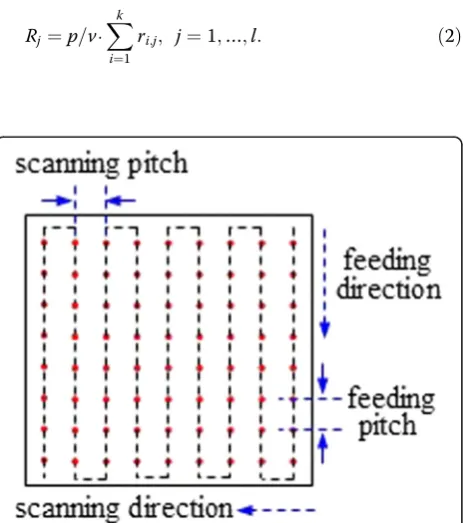
of generality, we modelled variable scanning pitch result-ing in a uniform removal map as well as variable removal map under the same scanning pitch, to reveal the effects of the canning pitch and removal depth on the residual ripple and MSF error. Herein, we consider a Magnetor-heological Finishing (MRF) TIF traversing a uniform pitch raster path, under the condition that the feeding direction is set in perpendicular to the fluid flow direction as shown in Figs. 3 and 4. As the TIF traverses a single line path with a constant feeding velocity ofv, the removal is uniformly distributed along the feeding direction, while the removal distributionRjin the perpendicular direction can be obtained by Eq.2 (see Fig. 5), in which TIF matrix (R,unit in um/s) hassrow,kcolumn elements as shown in Eq.3; and the pixel size isp(unit in mm).
Rj¼p=v⋅
Xk
i¼1
ri;j; j¼1;…;l: ð2Þ
R¼
r11 r12⋯ r1k
r11 r12⋯ r1k
⋯ ⋯ ri j⋯ rs1 rs2⋯ rsk
2 6 6 6 6
4 ð3Þ
Figure 6 shows the local removal amount distribution in the scanning direction while correcting uniformly-distributed form errors. The blue sections represent the removal amount in independent single path and the red one is the convolved removal amount. It is obvious that the convolved removal amount is periodically dis-tributed, and the spatial wavelength is identical to the scanning pitch. It is confirmed that surface form cor-rection by small-sized TIF inevitably induces residual ripple error.
Figure 7a shows that PVe becomes a linear growth along with the increment of the removal amount. It is suggested that a less removal amount is propitious to re-straint of PVe. Figure 7b shows the PVn value as a func-tion of scanning pitch. PVn increases as the scanning pitch is increased. It is noticeable that PVn increases slowly until the scanning pitch reaches ~1.1 mm, and then increases sharply. It is revealed that while correct-ing the surface form of optics by sub-aperture polishcorrect-ing, it is desired to adopt a smaller tool-path pitch for restraint of residual ripple.
Development of the multi-pitch tool path
Correction of the form error by CCOS processes aims to polish every region to a desired plane of absolute flatness, which is commonly located at the lowest point on the surface as shown in Fig. 8. In fact, a lower plane has to be selected due to the maximum motion speed of the tool. Such a removal map introducing extra removal isn’t propitious to restraint of residual ripples as revealed above.
If the desired plane selected at the lowest point, the desired removal amount at the point would be zero. As Fig. 2The relationships between the MSF error and the ripple features.aRms and ripple frequency and (b) Rms and ripple magnitude (Rms after band pass: 0.12-33 mm)
the tool traverses across the point, it inevitably removes material deteriorating figure convergence, thus the tool are commonly driven with a most velocity allowable for the machine. Furthermore, the path pitch within lowest regions should be as large as possible so as to introduce less over-removal, but in uniform pitch tool path, a large pitch would deteriorate the residual ripple errors. Therefore, we develop a multi-pitch tool path which has a large pitch in less re-moval regions reducing over-rere-moval and small pitch in more removal regions so as to decrease the residual ripples while guaranteeing the figure convergence.
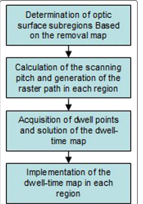
The polishing procedure with the multi-pitch tool path is showed in Fig. 9. First, we should generate the removal map according to the actual surface figure and the desired surface figure. Then, the removal map is divided into sev-eral subregions based on the removal variance. After that we calculate the scanning path pitch and generate the path for each subregion. The spacing between adjacent dwell points along each path line, i.e. the feeding pitch, is also determined. The feeding pitch can be adopted within a wide range, yet value of the scanning pitch is recom-mended. After determination of the scanning and feeding pitches, we then acquire the dwell points on the whole surface. The polishing time at each dwell point (i.e. the dwell map) can be solved with various algorithms such as discrete convolution model, the linear equation model and so forth [17]. Finally, the CNC code can be generated
according to the dwell point on the path and the dwell time map.
Determination of the path pitch in each subregion
While generating multi-pitch tool path, we first divide the optic surface into several subregions according to the re-moval map. The whole material rere-moval scope within the maximum and minimum removals is divided into several ranges, and then each removal range determines the cor-responding subregions. The number of the removal ranges or subregions depends on the whole removal scope; the larger the removal, the more the ranges or subregions. Generally, 3 ~ 6 removal ranges or subregions are appro-priate for most cases. Assuming a removal map has a maximum removal ofrand a minimum removal of 0, it is divided into m subregions and the removal variance in each subregion has the same value dr, then the removal in each subregion can be derived by Eqs.4–5.
k−1
ð Þ⋅Δr≤rk<k⋅Δr; k¼1;…;m: ð4Þ
Δr¼r=m ð5Þ
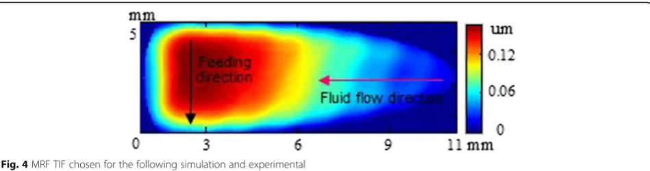
While determining the path pitch in a subregion, a dwell point P which has a removal of h and covers a square area in the subregion is considered, as shown in Fig. 10. The removal is almost uniformly distributed in the tiny square area, and then the correlation among the Fig. 4MRF TIF chosen for the following simulation and experimental
removal depth (r), path pitch (d) and feeding velocity (v) can be obtained by Eq.6. It is revealed that a certain d can be calculated for a given s, r and vmax, as shown in Eq.7.
s¼r⋅d⋅v ð6Þ
d¼s=ðr⋅vmaxÞ ð7Þ
In Eqs.6-7 h represents the feeding pitch, vmax the
largest feeding velocity allowed by the machine, and sis the volume removal rate of the TIF, which can be de-rived by Eq.8:
s¼p2⋅X l
j¼1
Xk
i¼1
Ri;j ð8Þ
Where p (unit in mm) is the pixel size of the TIF, and Ri,j (unit in um) is the TIF removal rate.
As revealed in the previous section, minimum path pitches are desired for restraint of residual ripple errors. Eq.7 indicates that the feeding velocity is inversely propor-tional to the pitch; thus, we can adopt a maximum feeding velocity allowed by the machine so as to decrease the pitch.
However, increasing feeding velocity has a significant im-pact on the stability of TIF. A too large feeding velocity will result in alteration of TIF, and hence deteriorate efficiency of figure correction as well as MSF errors. Further, the ma-chine imposes restrictions on the moving velocity and ac-celeration of every movable component. Hence, there is a favorable maximum velocity allowed for each polishing ma-chine. Herein, the largest feeding velocity (vmax) allowed by
the machine can be adopted in practice so as to reduce the pitch and hence the PVe.
As each subregion is determined within a material re-moval range, we adopt the minimum rere-moval depth in each region for calculation of the corresponding path pitch (see Eq.9), which will prevent the feeding velocity exceeding the specified maximum value. Then, the pitch in each region can be obtained by Eq.10.
r1¼0:5⋅dr;rk¼ðk−1Þ⋅dr; k¼2;…;n: ð9Þ
dk¼s=ðrk⋅vmaxÞ ð10Þ
In CCOS processes, the scanning path pitch should be restricted within a range in practice. The minimum value of the pitch is determined by the positioning & moving precision of the polishing machine. The maximum one is Fig. 6Removal distribution in the scanning direction
primarily dependent on the TIF size (i.e. <1/6 size). Fur-ther, a too large path pitch isn’t propitious to correcting the form error and restraining the ripple error.
Solution and implementation of dwell time map
Dwell time map in terms of the polishing time at each dwell point provides the time that the tool dwells on the corresponding position to obtain desired removal. In the multi-pitch tool path, the dwell points are
allocated at each path line with a feeding pitch. The feeding pitch can be specified according to the scan-ning pitch. Then, the dwell time map is solved by any developed algorithms, such as the discrete convolution method, linear equation method and so forth. The local feeding velocity (vf) can be derived from the pitch
and the local removal (rf) at the corresponding point, as revealed in Eqs.11–12. In the multi-pitch tool path, the removal variance in each region is greatly de-creased compared to the conventional tool path with a constant pitch on the whole optic surface. As the tool scans the path lines in any subregion, the path pitch is decreased as much as possible in every region, which is prone to improving the implementation precision of the dwell-time.
s⋅t¼rf⋅d⋅vf⋅t ð11Þ
Fig. 8Schematic of material removal distribution by the CCOS process
Fig. 9Polishing procedure with multi-pitch path
Fig. 10Dwell point in the uniform removal map
vf ¼s= d⋅rf
ð12Þ
During generation of multi-pitch tool path, the optic surface is divided into several regions. In each region, the tool scans a raster path with a featured constant pitch. The pitch is dependent on the removal in the region, and the larger the removal, the smaller the pitch. During im-plementation of the dwell time map, the tool will traverse all the paths that generated covering the whole surface. Herein, we suggest that each region be scanned individu-ally. In each region, adjacent path lines can be intercon-nected at the ends during implementation of the dwell-time map. As the tool traverses a path line and reaches the end, it translates to the nearby end of the next line and traverses this line (see Fig. 11). The translation stroke from one line to another maybe introduces extra dwell time, which will cause undesired removal and deteriorate the convergence rate of the surface form. If the tool lifts up after completing the last feeding segments in each path line, it will inevitably introduce extra removal during the lifting process. It is suggested that the tool lifts up while traversing the last feeding segment within a period longer than the determined dwell time. At this condition, the increased actual dwell time will compensate the decreased removal function achieving approximately the desired
removal. Similarly, the tool descends while traversing the first feeding segment of the next path line. After the tool has covered one subregion, it also lifts off the optic and translates above to the first dwell point of another sub-region. Then it descends to accomplish the subsequent dwell time. The lifting of the tool during the translation process wouldn’t bring with extra removal.
Results and discussion
Herein, we utilize the multi-pitch tool path and regular uniform pitch tool path for figure correction with MRF process. The two paths are compared through simula-tion and experiments.
MRF process is a typical CCOS process characterized by the stable TIF and deterministic figuring procedure. The MRF machine has x, y, z axes for translation motions, C axis for rotation motion and A axis for swing motion. The maximum translating velocity of the x, y, z axes allow for 50 mm/s. The diameter of the wheel is 300 mm. The spot-ting and figuring processes are conducted under the con-dition: wheel speed 200 rpm, MR fluid ribbon height 1.6 mm and the penetration depth of the optic into the ribbon 0.4 mm. The magnetic field strength applied to the MR fluid ribbon is also stably controlled. The TIF ob-tained by spotting process is showed in Fig. 4.
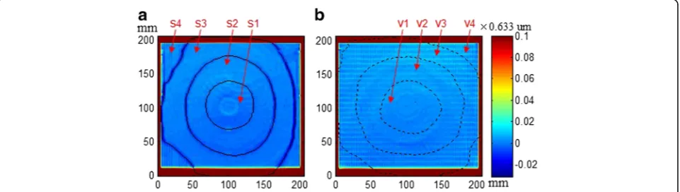
Fig. 12Initial figures of the optics polished with (a) multi-pitch and (b) uniform pitch tool path
We used two 200 mm × 200 mm sized optics (1#,2#). The optics are previously ground and polished with con-tinuous polishing process. They both have a favorable initial MSF error specification because the continuous polishing has distinct advantage in restraint of MSF er-rors. Figures of the both are similarly distributed with a PV value of approximately 0.443um, as shown in Fig. 12. In the following, we employed the TIF to correct the optic figures respectively.
The practical feeding velocity is set to 50 mm/s for determining the pitches. We then calculate the desired pitch for each removal depth by Eq.7. Herein, 1# optic is polished with multi-pitch tool path, while 2# optic with uniform pitch tool path for
comparison. The removal map of 1# optic is divided into 4 regions, and the removal depths in the regions are as follows: 1) 0 ~ 0.0633um, 0.0633 ~ 0.190um, 0.190 ~ 0.316um, 0.315 ~ 0.443um, then the pitches in the regions can be obtained: 0.8, 0.395, 0.132, 0.099 mm. The pitch of 2# optic is set at 0.8 mm on the whole surface.
The dwell points are generated with a feeding pitch of 0.3 mm along every path, and the dwell time map is solved by common discrete convolution algorithm. Then the CNC code for controlling the kinematics of the MRF machine is generated based on the dwell point and dwell time. The simulation and experimental results are shown in Figs. 13, 14 and 15.
Fig. 14Polishing results of the 1# and 2# optic figures with (a) multi-pitch and (b) uniform pitch tool pathss
The both optics have a surface form of approximately 0.095um PV after polishing with multi-pitch and uniform pitch tool paths respectively in simulation and experi-ments. In the uniform pitch path, the residual ripples are fairly large and non-uniformly distributed depending on the local removal. The regions with more removal have larger residual ripples. In contrast, the multi-pitch polished optic exhibits superiority in restraining residual ripple. As the more removal regions with a much smaller pitch path, the residual ripples are restrained. It is notice-able that the optic polished with multi-pitch path has slight depression at the edge between adjacent regions due to that the tool translation stroke from one path line to another introduces extra removal. Although, the depres-sion is so small that it has little effect on the figure error.
Conclusions
A multi-pitch tool path was developed for CCOS pro-cesses. With this tool path, the removal map is divided into several subregions, and the pitch in each subregion is set individually. In small removal subregions, the pitch is larger introducing less extra removal so that guarantee the convergence of the figure correction, while the large re-moval subregions the pitch is smaller so as to decrease the residual ripples. The multi-pitch tool path has been veri-fied that it is beneficial to restraining the ripples while maintaining the convergence of the figure correction.
Abbreviations
CCOS:Computer-controlled optical surfacing; MRF: Magnetorheological Finishing; MSF: Middle spatial frequency; PSD: Power spectral density; PVe: Peak-to-valley value of the ripple; PVn: Normalized PV value of residual ripple; TIF: Tool influence function
Acknowledgements Not applicable.
Funding
This work was supported by Science Challenge Project of China, No. JCKY2016212A506–0501.
Availability of data and materials Data will be shared after publication.
Authors’contributions
DL and JH developed the multi-pitch tool path; HW assisted conducting the experiments. All authors read and approved the final manuscript.
Ethics approval and consent to participate Not applicable.
Consent for publication Not applicable.
Competing interests
The authors declare that they have no competing interests.
Publisher’s Note
Springer Nature remains neutral with regard to jurisdictional claims in published maps and institutional affiliations.
Received: 14 June 2017 Accepted: 24 August 2017
References
1. Betti, R., Hurricane, O.A.: Inertial-confinement fusion with lasers [J]. Nat. Phys.
12(5), 435–448 (2016)
2. Pohl, M., Börret, R.: Simulation of mid-spatials from the grinding process [J]. J. Eur. Opt. Society-Rapid Publ.11, (2016)
3. Almeida, R., Börret, R., Rimkus, W., et al.: Polishing material removal correlation on PMMA–FEM simulation [J]. J. Eur. Opt. Society-Rapid Publ.11, (2016) 4. Wang, C.J., Cheung, C.F., Ho, L.T., et al.: A novel multi-jet polishing
process and tool for high-efficiency polishing [J]. Int. J. Mach. Tools Manuf.115, 60–73 (2017)
5. Arnold, T., Boehm, G., Paetzelt, H.: New freeform manufacturing chain based on atmospheric plasma jet machining [J]. J. Eur. Opt. Society-Rapid Publ.11, (2016)
6. Tamkin, J.M., Milster, T.D.: Effects of structured mid-spatial frequency surface errors on image performance [J]. Appl. Opt.49(33), 6522–6536 (2010) 7. Hu, H., Dai, Y., Peng, X.: Restraint of tool path ripple based on surface error
distribution and process parameters in deterministic finishing [J]. Opt. Express.18(22), 22973–22981 (2010)
8. Wang, C., Yang, W., Ye, S., et al.: Restraint of tool path ripple based on the optimization of tool step size for sub-aperture deterministic polishing [J]. Int. J. Adv. Manuf. Technol.75(9–12), 1431–1438 (2014)
9. Dai, Y.F., Shi, F., Peng, X.Q., et al.: Restraint of mid-spatial frequency error in magneto-rheological finishing (MRF) process by maximum entropy method [J]. Sci. China Ser. E: Technol. Sci.52(10), 3092–3097 (2009)
10. Wang, C., Wang, Z., Xu, Q.: Unicursal random maze tool path for computer-controlled optical surfacing. Appl. Opt.54(34), 10128–10136 (2015 Dec 1) 11. Yu, G., Li, H., Walker, D.: Removal of mid spatial-frequency features in mirror
segments [J]. J. Eur. Opt. Society-Rapid Publ.6, (2011)
12. Dunn, C.R., Walker, D.D.: Pseudo-random tool paths for CNC sub-aperture polishing and other applications [J]. Opt. Express.16(23), 18942–18949 (2008) 13. Walker, D.D., Yu, G., Bibby, M., et al.: Robotic automation in computer
controlled polishing [J]. J. Eur. Opt. Society-Rapid Publ.11, (2016) 14. Zhang, X., Yu, J., Zhang, Z., et al.: Analysis of residual fabrication errors
for computer controlled polishing aspherical mirrors [J]. Opt. Eng.
36(12), 3386–3391 (1997)
15. Cheng, H.B.: Independent variables for optical surfacing systems [M], p. 76. Springer-Verlag, Berlin (2014)
16. Spaeth, M.L., Manes, K.R., Widmayer, C.C., et al.: The National Ignition Facility wavefront requirements and optical architecture [C]. SPIE.5341, 25–42 (2004) 17. Wang, C., Yang, W., Wang, Z., et al.: Dwell-time algorithm for polishing large