© Copernicus GmbH 2004
Advances in
Radio Science
Integral equation analysis of complex (M)MIC-structures with
optimized system matrix decomposition and novel quadrature
techniques
T. Vaupel1and V. Hansen2
1FGAN-FHR, Neuenahrer Str. 20, 53343 Wachtberg, Germany
2Department of Electromagnetic Theory, University of Wuppertal, Germany
Abstract. Using integral equation methods for the analy-sis of complex (M)MIC structures, the computation and stor-age effort for the solution of the linear systems of equations with their fully populated matrices still forms the main bot-tleneck. In the last years, remarkable improvements could be achieved by means of diakoptic methods and related precon-ditiners. In this contribution, we present a method based on the optimized decomposition of the system matrix depend-ing on the circuit topology. The system matrix is splitted in a densely populated matrix and a mainly blockdiagonal matrix with overlapping submatrices. The latter matrix is used for the generation of high performance precondition-ers within Krylov subspace methods using sparsified matrix storage methods, adaptive Cholesky decompositions and op-timized forward/backward substitutions. Furthermore, we present an integration technique using a complete analytical treatment for the strongly oscillating parts of the spectral do-main integrands allowing the analysis of very large structures as compared to the wavelength.
1 Introduction
For the analysis and design process of (M)MIC structures, in-tegral equation techniques based on the method of moments (MoM) are well suited and widely used. Many new tech-niques have been introduced for the efficient generation of the system matrix as well as for the computational effort re-duction during the solution of the linear systems of equa-tions. However, problems may still occur for large structures as compared to the wavelength and with complex topology. Based on the techniques in (Vaupel and Hansen, 2001)(Vau-pel and Hansen, 2002), an optimized system matrix decom-position is now performed leading to high performance pre-conditioners whereas the application of a Legendre-Filon quadrature allows the versatile treatment of highly oscillatory Correspondence to: T. Vaupel
spectral domain integrands. The basic idea for the optimized system matrix decomposition stems from the experiences with the diakoptics-based MoM implementations given in (Ooms and De Zutter, 1998). The generation of macro ba-sis functions (MBs) is extended to entire domain diakoptic basis functions using block Gauss-Seidel procedures, but we could prove in (Vaupel and Hansen, 2002), that this approach still behaves∼O(N3). On the other hand, a direct iterative improvement of the current distribution derived by the MBs using block relaxation processes did not converge (Ooms and De Zutter, 1998). We can show now, that this diverging be-havior can be traced back on an insufficient system matrix decomposition used during the relaxation process. We have derived rules leading to an extended system matrix decom-position which guarantees fast convergence within a block Jacobi process and is especially well-suited for high perfor-mance preconditioners.
The creation of the system matrix of large structures re-quires the evaluation of spectral domain integrals with highly oscillatory integrands. To overcome this, several strategies (e.g. Pilz and Menzel, 1999) based on Filon integration prin-ciples (Filon, 1928) have been proposed, but they mainly suf-fer from a low integration order. Thus, we have extended the Gauss-Legendre quadrature by solving small linear systems of equations with modified right hand sides providing inte-gration weights already containing the oscillatory parts of the integrands.
2 Formulation
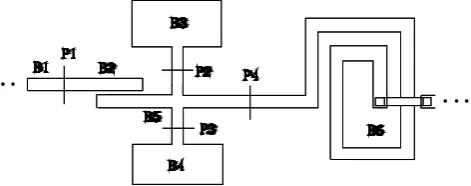
Fig. 1. Section of a typical (M)MIC-structure with port and block numbering.
For example port 3 excites block 3 and block 5. The current profiles on the corresponding blocks (computed with stan-dard MoM) form the MBs. In the next step, we perform an upper level MoM by computing the couplings between the MBs, for example the coupling between the MBs “k” and “l” is computed by
Zkl=
X
m∈MBk
X
n∈MBl
ImkZnmInl (1)
withZnm the entries of the lower level MoM,m∈ MBk is the indexmof all basis functions allocated to the MB num-berk,Imk the current profile of thekth MB etc. TheZklare the entries of the upper level MoM system matrix. Solving for the amplitudes of the MBs and the subsequent superpo-sition of the weighted current profiles of the MBs lead to a first approximation of the overall current distribution, but of-ten the error exceeds 10%. To diminish this error, a block Gauss-Seidel process was proposed (Ooms and De Zutter, 1998), applied to each MB, transforming the original sub-domain MB into an entire sub-domain diakoptic basis function within a few iterations. The weighted superposition of the diakoptic basis function provides again the overall current. The error remains below 1% compared to a direct solution, but we could already show (Vaupel and Hansen, 2002), that the overall process is still∼O(N3), but is 10–30 times faster than the direct solution.
To reduce this high numerical complexity, a direct im-provement of the current distributionI0provided by the sub-domain MBs was proposed, performing the block Jacobi pro-cess
Zi·In+1=U−Zc·In, Z=Zi+Zc (2)
usingI0as start vector.
Ziis proposed a sparse block diagonal matrix containing the self and mutual couplings of each block forming diago-nal submatrices, whereas Zccomprises all remaining mutual couplings.
Unfortunately, this process does not converge in most cases since the convergence condition
ρ(Zi−1Zc)<1
cannot be fulfilled with the chosen matrix decomposition whereρ(A)denotes the spectral radius of a matrix A.
But we get a convergent Jacobi process by using an ap-propriate extension of the matrix Ziemploying the following rule: If block s and block t form together a MB, i.e. it exists a current coupling between the two blocks, then the submatrix Zstmust be added to the matrix Zi.
For the structure in Fig. 1 we create the following matrix Zi:
Zi=
Z11Z12 0 0 0 0 Z21Z22 0 0 0 0 0 0 Z33 0 Z35 0 0 0 0 Z44Z45 0 0 0 Z53 Z54Z55Z56 0 0 0 0 Z65Z66
(3)
We can recognize an additional subdivision of this matrix into three further quadratic submatrices Z1. . .Z3where Z1 comprises the submatrices from Z11to Z22, Z2the submatri-ces from Z33to Z55and Z3the submatrices from Z55to Z66, thus Z3 overlaps with Z2 in their common submatrix Z55. We can observe that the topology of the (M)MIC-circuitry is completely transferred to the submatrix decomposition of Zi. As next step, we perform an adapted Cholesky decom-position of Zi using the described submatrix decomposition thus minimizing the number of computational steps. In this context, we can also perform an incomplete Cholesky de-composition to avoid possible fill-ins of matrix entries. The Cholesky decomposition, denoted with C, can be used to per-form Eq. (2), but it is much better to use it as left and right preconditioner within Krylov subspace methods, employing the equivalent linear system of equations
C−1Z C−TCT·I=C−1·U. (4)
This results in decisive benefits in contrast to Eq. (2): - about the same computational effort per iteration as Eq. (2)
- excellent convergence behavior nearly independent on start vector
- No explicit generation of MBs with additional port exci-tation necessary
⇒block decomposition also at broad transmission lines, arbitrary structure excitation
- fast convergence also with incomplete Cholesky decom-position.
Another problem arising with large structures is combined with strongly oscillating coupling integrands.
Regarding e.g. the coupling integral of two x-directed ba-sis functions we get
Znm= kx,a
Z
kx=0
ky,a
Z
ky=0
GEJ xxRe{Fm0(kx)Fn0(kx)ej kx1xnm}
Re{Fm0(ky)Fn0(ky)ej ky1ynm}dkxdky. (5) Here, Fm0 ,Fn0 denote the Fourier transforms of the
high number of sampling points is necessary using standard quadrature techniques. To overcome this constraint, we em-ploy the following procedure, e.g. outlined for the integration with regard tokx.
The aim is to integrate b
Z
a
f (kx)ej c kxdkx ≈Csc
N
X
j=1
˜
wjf (xj) (6)
withf (kx)typically a smooth function ofkx,w˜j integration weights adapted toej c kx andx
j appropriate sample points. Using the substitutionkx(t )= b−a2 t+a+b2 , dkdtx = b−a2 , we can introduce the Legendre expansion
f (kx(t ))= N−1
X
n=1
anpn(t ), t ∈ [−1,1] (7)
withanthe expansion coefficients. We can write b
Z
a
f (kx)ej c·kxdkx=
1 Z
−1
f (kx(t ))ej c·kx(t ) dkx
dt dt≈
b−a 2 e j·e N−1 X n=1 an 1 Z −1
pn(t )ej d·tdt (8)
withd = c·(b−a)
2 , e =
c·(b+a)
2 andCsc =
b−a
2 e
j·e. The best approximation for the integral with the given Legendre expansion is obtained if we achieve
N−1 X n=1 an 1 Z −1
pn(t )ej d·tdt= N−1 X n=1 an N X j=1 ˜
wjpn(tj), n=0, .., N−1.
(9) For this goal, we have to fulfill
1 Z
−1
ej d·tpn(t )dt =
N
X
j=1
˜
wjpn(tj), n=0, .., N−1. (10)
This leads to the generation of the linear system of equations
p0(t1) p0(t2) . . . p0(tN) p1(t1) p1(t2) . . . p1(tN)
..
. ... ... ... pN−1(t1) pN−1(t2) . . . pN−1(tN)
· ˜ w1 ˜ w2 .. . ˜ wN = = 1 R −1
p0(t )ej d·tdt
1 R
−1
p1(t )ej d·tdt
.. .
1 R
−1
pN−1(t )ej d·tdt, . (11)
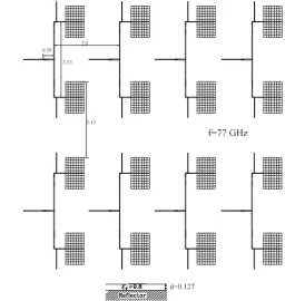
Fig. 2. Discretization of a 16-element patch array.
whose solution provides the integration weightsw˜i. The ma-trix has only to be computed once using the well known re-currence formula for the Legendre polynomials. Afterwards, we apply a LU-decomposition of this matrix with partial piv-otisation and additional storage of a pivot index vector.
Thus the efficient computation of the right hand side of Eq. (11) forms the crucial point for the weight determination.
Here the main task is to solve
Tn(d)=
1 Z
−1
tnej d·tdt= 1
j dt nej d·t
1 −1 − n j d 1 Z −1
tn−1ej d·tdt
(12) by a recurrence relation. For the first term right hand side in Eq. (12), we get
1 j dt
nej d·t 1
−1
=
( 2
dsin(d), neven
2
j dcos(d), nodd
. (13)
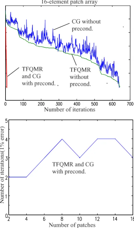
Fig. 3. Solution behavior of 16-element patch array. Top: Con-vergence history. Bottom: Iteration number in dependence on the number of patches.
The effort for computing the weights can be further re-duced by using a composite Legendre-Filon integration. This means that the sampling points are subdivided into several intervals whereas the weights are only computed for the first intervall. The weights for the other intervalls are simply de-rived from the weights of the first intervall by multiplying them with a fixed exponential term.
3 Applications
As first application we present the analysis of a 16-element patch array consisting of 2-element subarrays. Figure 2 shows the dimensions and discretization of the structure.
The structure was discretited with 2400 basis functions. For the matrix decomposition, we introduced 40 ports lead-ing to 48 blocks.
Fig. 4. Multibeam antenna array as part of an astronomical tele-scope. g=0.15 mm, c=1.1 mm.
Fig. 5. Current distribution (A/mm) of a multibeam antenna excited by an incident plane wave at f=250 GHz.
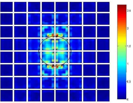
Fig. 6. Current distribution of a multibeam antenna excited by an incident plane wave only illuminating a circular region with diame-ter 3.05 mm.
A so-called multibeam antenna we present as a second ap-plication. It is intended as part of astronomical telescopes for image processing purposes in the submm-wave region. As given in Fig. 4, it consists of 64 patch elements mounted on a foam layer (r ≈1.2) with reflector. We applied a dis-cretization with 2560 unknowns. The lateral dimension of the structure amounts to about 12 wavelength at 250 GHz. For the preconditioning, each antenna element was assigned to one block at first, but we also assigned two elements to one block. The two-element blocks can be considered as iso-lated or we can introduce so-called virtual ports between the elements. With virtual ports between successive elements e.g. in each row, the elements of a row are considered as connected by current coupling although only field coupling exists between the elements. This leads to overlapping ma-trices similar as in in Eq. (3). Nevertheless, the performance of this preconditioning strategies is nearly the same and leads to about 11 iteration using a perpendicular plane wave exci-tation (E-field in x-direction with 1000 V/cm) over the whole array (Fig. 5). If we only illuminate a circular region of the array (Fig. 6), we need up to 24 iterations which can be traced back on the inhomogeneous excitation situation.
4 Conclusions
An optimized system matrix decomposition adapted to the topology of complex (M)MIC-structures was presented, leading to high performance preconditioners within Krylov subspace solvers. Using adaptive Cholesky decompositions and forward/backward substitutions, the computational and storage effort for the solution process of the linear systems of equations could be minimized. For the very accurate evalua-tion of the system matrix entries a Legendre-Filon integraevalua-tion technique was applied to the often highly oscillatory spec-tral domain integrands formulated in Cartesian wavenum-bers. The methods were applied to microstrip array antennas and multibeam reflectarrays and have demonstrated excellent performance for both the matrix fill and the linear equation solution process.
References
Ooms, S. and De Zutter, D.: A New Iterative Diakoptics-Based Multilevel Moments Method for Planar Circuits, IEEE Trans. on Microwave Theory and Techn., 46, 3, 280–291, 1998.
Vaupel, T., Hansen, V., and Sch¨afer, F.: Radiation Efficiency Anal-ysis of Submm-Wave Receivers Based on a Modified Spectral Domain Technique, Radio Science, 38, 4, 2003.
Vaupel, T. and Hansen, V.: Integralgleichungsanalyse von (M)MIC-Strukturen mit modifizierter Spektralbereichsintegration und di-akoptischen Strategien, Kleinheubacher Berichte, 2001. Vaupel, T. and Hansen, V.: Anwendungen einer modifizierten
Spek-tralbereichsintegration f¨ur implizite Multilevelstrategien und de-taillierte Abstrahlungsanalysen, Kleinheubacher Berichte, 2002. Filon, L. N. G.: On a quadrature formula for trigonometric integrals,
Proc. Roy. Soc. Edinburgh, 49, 38–47, 1928.