ORIGINAL ARTICLE
Active Profiling and Polishing Model
and Validation Based on Rotor Spiral Groove
Guo Yu
1, Feng Li
2*, Yong‑Min Yu
3and Shou‑Xiang Zai
4Abstract
When a spiral groove is formed using superplastic molding, precision casting, additive manufacturing, or other non‑ mechanical processing technology, it is difficult to meet the molding precision required for direct use, and the surface quality and accuracy of the shape need to be improved through a finishing process. In view of the poor reachability of the current tool‑based polishing process, a tool‑less polishing method using free‑abrasive grains for complex spiral grooves is proposed. With this method, by controlling the movement of the workpiece, the design basis and relative motion of the abrasive particles along a helical path remain consistent, resulting in a better polishing profile. A spiral groove of a revolving body is taken as the research object; the influence of the installation method and the position of the parts, as well as the effect of the rotational speed of the abrasive ball on its relative motion along a helical trajec‑ tory, are studied, and the polishing cutting process of an abrasive ball is reasonably simplified. A consistent math‑ ematical model of the trajectory of an abrasive ball relative to the design helix is constructed. The grooved drum parts are verified through a polishing experiment. The spiral groove of the revolving body is modified and polished. Experi‑ ments show that the process not only corrects the shape a spiral groove error, but also reduces the surface roughness of a spiral groove. This study provides a theoretical basis for achieving free‑abrasive, tool‑free polishing.
Keywords: Revolving body, Spiral groove, Abrasive ball, Active profiling, Modified and polished, Model verification
© The Author(s) 2018. This article is distributed under the terms of the Creative Commons Attribution 4.0 International License (http://creativecommons.org/licenses/by/4.0/), which permits unrestricted use, distribution, and reproduction in any medium, provided you give appropriate credit to the original author(s) and the source, provide a link to the Creative Commons license, and indicate if changes were made.
1 Introduction
Rotary parts with complex spiral grooves are frequently applied to the aerospace, automobile, textile machinery, and petrochemical engineering industries [1, 2]; how-ever, for some closed spiral grooves with complex shapes or structures, the formation and finishing of the parts remain a problem [3, 4]. Superplastic molding, preci-sion casting, additive manufacturing, and other non-mechanical processing for the formation of complex structural parts have significant advantages [5–7]. How-ever, because it is difficult to attain the molding precision required for direct use, the spiral groove formed using these molding methods requires a follow-up finishing to improve the surface quality and accuracy of the shape [7].
Computer-controlled deterministic polishing is the main method used to improve the accuracy of a complex
curved surface shape [8, 9]. This type of polishing mainly applies CNC polishing technology with a small grind-ing head [10, 11], balloon polishing technology [12–14], magneto-rheological polishing technology [15, 16], ion beam polishing technology [17, 18], and jet polishing technology [19]. Because computer-controlled determin-istic polishing is accomplished by controlling the amount of material removed through control of the tool’s resi-dence time (or feed rate) at different points on the sur-face [20–23], surface errors need to be calculated based on the actual surface measurements prior to polishing. Moreover, a quantitative modeling and analysis should be conducted on the material removal when polishing with the aim of controlling the amount of materials removed in an accurate manner. The material removal rates of dif-ferent points on a work piece surface vary owing to the complexity of the free-form surface, and coupled with the influence of other factors, it is difficult to establish a precise mathematical model. Meanwhile, difficulty also exists in further improving the surface detection precision of the components owing to a limitation of
Open Access
*Correspondence: [email protected]
the use of a belt, wheel polishing, and electrochemi-cal polishing [25–27]. Among these, manual polishing is inefficient, and the surface processing effect is greatly influenced by the technical level of the workers, the pro-cessing consistency is poor, the production environment is harsh, and the health of the operators is impaired [25]. In addition, accessibility to the belt used in grinding wheel polishing for complex inner surfaces is not high, and cannot meet the processing requirements. Moreover, the problem of environmental pollution caused through the use of chemical solutions when applying electro-chemical polishing needs to be solved [26].
Free-abrasive polishing, with high process reachability, has significant advantages for the finishing of a complex lumen structure [28–33]. Zhang et al. [34] studied abra-sive water jet finishing, and established an abraabra-sive water jet removal model; however, the linear nature of the jet makes it difficult to achieve uniform erosion of all parts of a structured surface, and therefore the formation of good contoured contact and uniform machining results for a structured surface is not possible. Ji et al. [35] pro-posed a method using a soft milling ball without tool-precision machining, and the impact of soft abrasive flow particles and the particle volume fraction on the grinding effect were studied [28–33]. Zhang Kehua and Ding Jinfu respectively studied the removal force and micro-cutting mechanism. In addition, previous studies have achieved considerable results regarding the cutting mod-eling and machining of free abrasive particles [33, 36].
In summary, current studies on the finishing of a free-abrasive have mainly focused on improving the surface quality without involving the surface modification. In addition, current studies on the polishing of free-abra-sives mainly focused on the movement and control of a single abrasive grain, and research into the different parts has been lacking. The shape and structure of a spi-ral groove restrict its use as a polishing tool. Therefore, the free-abrasive grain of tool-less finishing is an effective way to improve the surface quality and accuracy of the shape of a non–machined spiral groove. In this paper, the spiral groove of a revolving body is taken as the research object. A method used to make a helical movement of a workpiece, and cut and polish an abrasive grain, is pro-posed. The principle of the relative motion of the abra-sive ball trajectory is studied. The trajectory and design helix are in concordance with a mathematical model. The
2 Establishment of Trajectory Control Model for Active Profiling and Polishing
In current free-abrasive machining and computer-con-trolled polishing, the polishing tool or abrasive particle movement are major aspects, whereas the workpiece is simply used for feed movement or immobility. It can be concluded from the relative movement that the move-ment of the tool or abrasive particle is active, whereas that of the work piece is passive. Therefore, aiming at achieving rotational spiral parts, in this study, a polishing mode that enables the active movement of the work piece as well as the passive relative movement of the abrasive particles, defined as “active polishing,” was developed, and the concept of “active profiling and polishing” was put forward, which means generating relative movement between abrasive particles and applying a design basis through the movement of the central workpiece, thereby producing a high profile polishing.
In traditional profile polishing, the profiling reference is a polishing tool or abrasive particles, which move along the surface to be machined and remove materials in a uniform manner, achieving a processed surface. As a result, traditional profiling and polishing can only lower the surface roughness instead of improving the accuracy of the shape. In active profiling and polishing, abrasive particles generate relative movement according to the design basis, which marks the profiling for the design basis. Hence, active profiling and polishing can demon-strate a correction of the shape error of the surface to be machined.
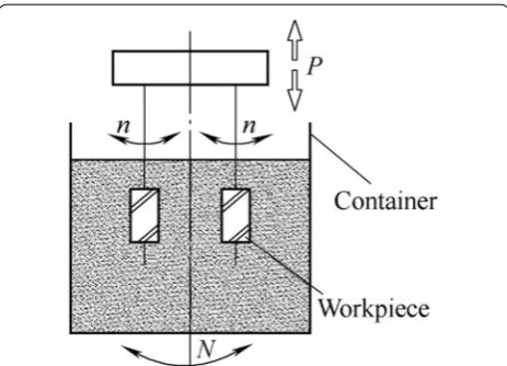
In order to realize active polishing, the relative motion between the abrasive ball and spiral groove part needs to meet the following conditions: a spiral relative motion curve consistent with the design basis. Based on the use of a cyclone finisher, adding the upward and downward motion equipment, the rotational parts rotate up and down at the same time, and as a result, the trajectory of the rotational part point has a spiral curve.
(at a rotational speed of N r/min), which remain com-pletely submerged in the abrasive balls while in motion. The formation principle of relative motion and spiral curves indicates that the helical curve formed by n and P marks the motion curve of the points on the workpiece surface; relative movements of the surrounding abra-sive balls toward the components are − (n +N) (r/min) and −P (mm/min). Hence, the helical curve formed by − (n +N) and −P is the relative movement of the sur-rounding abrasive balls.
Assuming that +n is the rotational motion of the workpiece, −N will be the rotational motion of the feed cylinder. Thus, the rotational speed and linear velocity synthesis of the abrasive balls relative to the workpiece will be
When the workpiece rotates at a speed of n, the linear velocity ν1 encircling the work piece will be
When the roller is conducting a rotation at a speed of N, regardless of the rotation of the abrasive balls, the lin-ear velocity ν2 of the balls tangent to the encircling of the workpiece and rotating with the feed cylinder will be
where R is the radius of gyration of the abrasive balls rotating with the feed cylinder encircling the work piece. In addition,
Moreover, the syntheses of the rotating speed and lin-ear velocity are on the same plane.
(1)
n−(−N)=n+N.
(2)
v1=Dπn.
(3)
v2=2πRN,
(4)
v1−(−v2)=v1+v2.
Assuming that P′, ν′(n + N), and ν′ mark the vertical velocity, linear velocity, and resultant velocity of move-ment of the abrasive balls relative to the encircling of the surface of the workpiece, respectively, when the work-piece conducts downward or upward movement, synthe-ses of helical motions by the abrasive balls relative to the workpiece are demonstrated, as shown in Figure 2.
In the figures above, ν′(n + N) demonstrates the result-ant linear velocity of the rotation of the principal axis and feed cylinder in Eqs. (5) and (6). The relative move-ment between the abrasive balls and workpiece surface is reversed, and is hereby changed into a positive move-ment for calculation, which means that when P =−P′, and ν=−ν′, the following are established:
Substituting ν1 and ν2 into Eq. (8), and generating β′, the lead angle of reverse motion by abrasive balls relative to the workpiece is
which indicates the movement relative to the work piece surface formed by the abrasive balls according to a helical curve with a lead angle of β′ when the workpiece is mov-ing at a rotational speed of n (r/min) and a linear velocity of P (mm/min).
It can be concluded from Eq. (9) that when D (work-piece parameter), R (mounting parameter), and N (motion parameter of the abrasive balls) are constant, adjusting the speed ratio between n and P can change β′, i.e., the lead angle of the relative motion by the abrasive balls.
If β′ can be made consistent with the design curve of a spiral groove on the workpiece surface through an
(5)
p2+(v1+v2)2=v2,
(6)
v=
p2+(v1+v2)2,
(7)
tanβ′=p/(v1+v2),
(8)
β′=arctan(p/(v1+v2)).
(9)
β′=arctan(P/(Dπn+2πRN)), Figure 1 Principle of active profiling and polishing for rotational
parts
groove, it can also correct any errors in shape.
Below, D is the diameter of the workpiece, S is the lead of the design curve of a spiral groove on the workpiece surface, and β is the lead angle of the helix, and thus, according to the formula of the lead angle,
Assuming β =β′, namely,
where P indicates the axial displacement distance of the workpiece, which is the time it takes for the helical curve to complete one lead, and n +2RN/D marks the rotational speed of abrasive balls relative to the work piece; in addition, the reciprocal of the rotational speed is the time it takes to complete one rotation. Therefore, Eq. (12) can be interpreted as the time it takes for the workpiece to travel the displacement distance of one lead of the designed helical curve, which is equal for the time required for abrasive balls to rotate one circle relative to the workpiece. This can also be demonstrated as
This demonstrates the relation model. The model can realize consistency between the spiral trajectory based on the relative motion of the abrasive balls and the design curve under different parameters for rotational parts, with a diameter of D and a surface-designed helical curve lead of S.
Although the relational model in Eq. (13) is established based on the surface helical curve of the rotational parts, when the rotational parts with spiral grooves conduct rotational motion and rectilinear motion at a certain speed, and when the abrasive balls produce a transverse feed movement through extrusion under the function of gravity and then enter the spiral groove at a relatively low speed, it can be considered that a variation of N, the rota-tional speed of the abrasive balls, is negligible. The lead angle of helical motion is only related to the speed ratio of rotational and linear motion. As a result, the relational
(10)
β=arctan(S/πD).
(11)
p
πDn+2πRN = S πD,
(12)
S p =1/
n+ 2R
D
,
(13)
P=
n+ 2R DN
S.
3.1 Analysis of Verification Scheme
Different parameters are needed in a polishing experi-ment for the purpose of verifying the trajectory control model of the active profiling and polishing. In Eq. (13), the maximum value of S is ∞, under which circumstance of the spiral groove becomes an axial slot, and the relative movement of abrasive balls that runs against the groove can be generated as long as n= 0, and P is any value other than zero; the minimum value of S is zero, under which circumstance the spiral groove becomes circular, and the relative movement of abrasive balls that runs against the groove can be generated as long as P = 0, and n is any value other than zero. Hence, there is no need to verify the limit values of S, n, and P. Instead, verification on one typical value will be sufficient. For the sake of the experi-ment, the aim is to verify one minimum limit value and one typical value of the other parameters.
(1) Instead of being an independent parameter, R in Eq. (13) is jointly determined based on the instal-lation location of the device and parameter D of the work piece. Changing R and D in a simultane-ous manner, the ratio between the two parameters will be constant. As a result, D can be verified as an overall parameter. When R = 0.5D marks the mini-mum value of R/D, the rotational center of the com-ponent will be consistent with the center of gyra-tion of the abrasive balls, which is referred to as a concentrically mounted state, as demonstrated in Figure 4. Under such circumstances, Eq. (13) can be expressed as (N + n)S.
(2) In Eq. (13), when N = 0, namely, when abrasive balls are at rest, P = nS.
Therefore, only the minimum values of D and N, and the typical values of all parameters, need to be verified when conducting verification on the trajectory control model of an active profiling and polishing.
3.2 Polishing Equipment
shows its major parameters. The work piece, which is mounted on the spindle box, can rotate (at a speed of n) under the driving force of the spindle. Meanwhile, it also conducts reciprocating motion (at a speed of P) with the spindle box under the driving force of the crank–link mechanism. Driven by the swing mechanism, the feed cylinder can enable joint rotation (at a speed of N) with inside the medium (abrasive balls). The work piece, which is completely submerged in the medium, can demon-strate linear and rotational motions when the polishing is applied. PLC can control the linear (P) and rotational motions (n) of the workpiece, and a joint rotation (at a speed of N) of the inside medium (abrasive balls).
3.3 Polishing Parts
A grooved drum of a winder was employed as the polish-ing component in the verification experiment. Figures 4 and 5 [39–41] show a polishing schematic and outline drawing of a superplastic alloy groove drum of a certain size, respectively. The finished grooved drum marks a hollow cylinder, which has a diameter (D) of 82 mm, an aperture (d) of 20 mm, and a length (L) of 176 mm; the depth of the groove in the drum varies from 2.4 to 23 mm, its narrowest width is 5 mm, and its wall thick-ness is 2.5 mm. In addition, the lead (I) is 152 mm. Direct
molding was applied with pressure. ZnAl5 superplastic alloy marks the material of the components, the mechan-ical properties of which under normal temperature are as follows: strength of extension of 30–33 kg/mm2, yield strength of 27–29 kg/mm2, elongation of 5%, and rigidity of HV71.
With the typical structure of a rotor spiral groove, the component is equipped with the function of a grooved cylindrical cam. The curve of the groove was designed to be a trade–off between a sinusoid and an exponen-tial curve. The left and right sides of the curve intersect, and a curve connection is employed at the reverse loca-tion for a transiloca-tion, forming a closed cycle. As a result, its groove shape is much more complicated than that of a common rotor spiral groove [21]. Therefore, it is of universal significance for the polishing of a rotor spiral groove to verify the groove drum.
3.4 Calculation of Typical Motion Parameter for Component Polishing
The spiral groove on the periphery of a grooved drum has a trade-off between a sinusoid and an exponential curve. The left and right sides are both closed, and recirculation is conducted. At a location near both ends, the pitch and rotation angle decrease to zero in a gradual manner, and then reverse. The major immediate section is similar to a linear segment on an expanded plane. The pitch and rotational angle remain essentially constant. The error of linear substitution is 7.063% [42]. Therefore, the motion parameter of the immediate section can be approxi-mated through Eq. (13). Specific parameters such as the workpiece parameters (D, S), motion parameters of the Figure 3 Structure of the polishing equipment
Table 1 Major parameters of the polishing equipment Cylinder
diameter D (mm)
Cylinder height H (mm)
Work-piece, head-stock distance R (mm)
Cylinder rotation speed N (r/min)
Work-piece speed n (r/min)
Workpiece up and down speed P (mm/min)
800 450 150 0–20 0–30 0–10
abrasive balls (N, R), and movement parameters of the workpiece (n) are substituted into Eq. (13) in accordance with the verification scheme, and P is then calculated under different conditions.
3.4.1 Determine the Speed of Workpiece
The value of n is extremely high, and it is difficult for the abrasive balls to enter the spiral groove under cen-trifugal force. Assuming that the rotational speed of the spindle n is 30 r/min, the lead is 152 mm, the pitch is 152/2 = 76 mm, and P is calculated under different conditions:
(1) When the feed cylinder does not rotate
The abrasive balls are at rest, namely, N = 0, and thus
(2) When the minimum value of D is chosen
Under a concentrically mounted state, R = 0.5D, and thus P = (N + n)S, assuming a rotational speed of the feed cylinder of N = 15 r/min.
(3) When a typical parameter is chosen
Substituting R = 150 mm and D = 94 mm into Eq. (13),
3.4.2 Calculate Frequency of Upward and Downward Movements of the Spindle Box
Here, P is the speed of the upward and downward move-ments of the axle box, and the pitch per minute is cal-culated respectively as 2280/76 = 30, 3420/76 = 45, and 5918.1960/76 = 77.8710.
Take the lead of the groove drum as the amplitude of the upward and downward movements of the spindle
P=n×s,P=30×76=2280 mm/min.
P=(30+15)×76=3420 mm/min.
P=(30+2×150/94×15)×76
=5918.1960 mm/min.
then implemented. The motion syntheses of the transi-tion sectransi-tion of both ends are as follows: n, the rotational speed of the spindle, remains unchanged, and P, the speed of the linear motion by the work piece, gradually decreases to zero. It then becomes negative and conducts a reverse movement. Movement of the work piece is real-ized through control using the PLC.
3.5 Conditions of Polishing Experiment
In the modeling process, only major factors are taken into consideration, and factors such as the rotation, extrusion, striking of the abrasive ball, and the centrifugal force are simplified in an appropriate manner, the reason for which is that the motion and forces of the abrasive balls when rotating along with the container are relatively compli-cated. Given the influence of the structure of the spiral groove on the feed movement of the abrasive balls (the mechanism and experiment on the polishing cutting are discussed later), the following items are required when verification on an active profiling and polishing model is conducted using rotor spiral groove parts:
(1) The diameter of an abrasive ball is significantly lower than the narrowest dimension of the spiral groove.
(2) An appropriate low–viscosity medium is added to the abrasive balls for cooling and lubrication, reduc-ing the friction and makreduc-ing it possible to assume that the influence of the fluid on the movement of abrasive balls can be neglected.
(3) When the speed ratio is constant, a lower rotational speed and a linear velocity of the work piece should be applied owing to the low speed of the feed move-ment generated through extrusion.
(4) At rotational speed N, the feed cylinder needs to be extremely high to lower the effect of centrifugal force.
Experiment conditions: The surface roughness of the work blank is between Ra 6.3–3.2, carborundum abra-sive balls with a diameter of Ø3 mm and size of #150 are applied as the polishing medium, clear water is used for the cooling and lubrication. The parameters of the abra-sive balls are shown in Table 2.
3.6 Process and Results of Polishing Experiment
A polishing experiment with three groups of superplastic alloy groove drums of identical size (each group repeated three times) was conducted, and the mean value was recorded. The calculated motion parameters are entered into the PLC for implementation of the polishing experi-ment. Thirty-six detection points (the distance toward the direction of the extended line is 8.4 mm, and that toward the peripheral direction is 10°) were set in one helical lead with the purpose of detecting the correction efficiency of this polishing method with regard to errors in shape. The ideal coordinate value of each point of the design curve is calculated, and an error of ± 0.01 mm is set. During the polishing process, the actual coordinates of each point were measured and compared with the ideal coordinates using a universal tool microscope, and dividing the head by the time interval. If the difference is less than 0.01 mm, the repair can be considered com-plete. If the 36 test points all meet the requirements, the actual curve can be considered to be in line with the ideal curve, and the error correction of the shape is completed. Table 3 shows the detection of the correct number of points during the polishing process.
In Table 3 and Figure 6, Group 1 demonstrates the state of minimum N, Group 2 indicates the state of mini-mum R, and Group 3 indicates the state of the typical parameters.
At 5 and 10 min in Table 3 indicate, a relative surface roughness still exists. Therefore, the coordinates are not determined.
In Group 1, at 30 min, the number of points can be detected, and at 50 min, all points of the actual coordi-nates satisfy the requirements.
In Group 2, at 25 min, the number of points can be detected, and at 40 min, all points of the actual coordi-nates satisfy the requirements, and the coordicoordi-nates tend to be stable.
In Group 3, at 15 min, the number of points can be detected, and at 30 min, all points of the actual coordi-nates satisfy the requirements, and the coordicoordi-nates tend to be stable.
The results indicate that an error in shape can be cor-rected under the three conditions mentioned above. This indicates that under the conditions in which the model relation is satisfied, regardless of how the parameters are changed, all parameters can realize active polishing, and the mode is reliable.
During the polishing process, it was found that the sur-face roughness of the spiral groove and the outer sursur-face were not changed much at 5, 10, and 15 min, and the surface roughness was significantly lower than that of the spiral groove at a time of 20 min. The roughness of the spiral groove and the outer surface are basically the same at 50 min, and no longer change. In this case, the Ra value was 0.93 μm as determined using a hand-held surface roughness meter. Therefore, it can be determined that the surface roughness value Ra of the spiral groove is also 0.93 μm. This indicates that the limit of the surface roughness for the spiral groove polishing under this par-ticular process condition is 0.93 μm.
Table 2 Parameters of the abrasive balls Hardness
HS Apparent poros-ity (%) Bulk density (g/cm3) Compressive strength (MPa) Thermal expan-sion coefficient (10/ °C)
Silicon carbide
content (%) Basic liquid Consistency (%)
≥ 115 < 0.2 > 3.10 > 2500 4.2 > 98 Water 60
Table 3 Number of correct points
Times (min) 5 10 15 20 25 30 35 40 50
Group 1 Group 2 Group 3
– – –
– – –
– – 30
– – 34
– 30 35
30 34 36
34 35 36
35 36 36
36 36 36
Figure 7 shows the polishing equipment, Figure 8 shows the surface roughness measurement for the polish-ing of Group 3, and Figures 9 and 10 show a comparison.
4 Conclusions
(1) Active profiling and polishing is a design basis pro-filing and polishing, and not only can improve the surface quality, but also the accuracy of the shape. Traditional profiling and polishing sets the surface to be machined on a profile basis. It can only reduce the surface roughness, and is unable to increase shape accuracy.
(2) The influencing factors and control methods of an abrasive ball relative to the spiral groove movement trajectory are proposed, a consistent mathematical model of abrasive balls relative to the movement trajectory and designed spiral curve is built, and a theoretical basis for the active profiling and polish-ing of a revolvpolish-ing body with a spiral groove is sup-plied.
(3) The spiral groove polishing experiments show that active profiling and polishing can increase the accuracy of the shape and the surface quality of a grooved drum, and has good polishing effective-ness. The problems in which deterministic
com-puter control of the spiral groove polishing is applied, the removal amount is difficult to deter-mine, and a polishing tool is required, are all solved. At the same time, a reference is provided to resolve the free-abrasive tool-less polishing problem. (4) A spiral trajectory of the relative movement of an
abrasive ball is not only affected by the installa-tion method, installainstalla-tion locainstalla-tion, and speed of the revolution, but also by the self rotation, squeeze, impact, and centrifugal force the abrasive ball. The Figure 7 Groove drum polishing equipment
Figure 8 Surface roughness measurement curve of polished parts
theoretical parameters of the model calculation need to be properly adjusted to achieve the best conditions, and the model needs to be further stud-ied and improved.
Authors’ Contributions
GY was in charge of the whole trial; GY and FL wrote the manuscript; GY, FL, Y‑MY, S‑XZ assisted with sampling and laboratory analyses. All authors read and approved the final manuscript.
Author details
1 School of Earth Sciences and Resources, China University of Geosciences, Beijing 100083, China. 2 Department of Mechanical Engineering, College of Information & Business, Zhongyuan University of Technology, Zheng‑ zhou 450007, China. 3 Electrical and Mechanical College, Zhongyuan Univer‑ sity of Technology, Zhengzhou 450007, China. 4 Automotive Institute, Henan Mechanical Electrical Secondary School, Zhengzhou 450007, China.
Authors’ Information
Guo Yu, born in 1991, is currently a PhD candidate at China University of Geosciences, China. His main research direction is precision machining. Tel: +86‑13903830850; E‑mail: [email protected]
Feng Li, born in 1981, is currently an associate professor at College of Infor-mation & Business, Zhongyuan University of Technology, China. He received his master degree on Mechanical Manufacture and Automation from Zhongyuan University of Technology, China, in 2010. Tel: +86‑13526645092; E‑mail: [email protected]
Yong‑Min Yu, born in 1964, is currently a professor at Zhongyuan University of Technology, China. His main research direction is precision machining. Tel: +86‑13525529778; E‑mail: [email protected]
Shou‑Xiang Zai is currently a teacher at Automotive Institute, Zhongyuan University of Technology, China. E‑mail: [email protected]
Competing Interests
The authors declare no competing financial interests.
Ethics Approval and Consent to Participate Not applicable.
Funding
Supported by Key Scientific & Technological Research Project of Henan Prov‑ ince, China (Grant No. 102102210497).
Publisher’s Note
Springer Nature remains neutral with regard to jurisdictional claims in pub‑ lished maps and institutional affiliations.
Received: 30 October 2016 Accepted: 16 March 2018
References
[1] Y C Kuang, F Shu, L M Wu, et al. Numerical simulation method of forming grinding wheel contour for complex spiral curved surfaces. Journal of Sichuan University (Engineering Science Edition), 2013, 45(2): 182–187. [2] K Wang, A Q Zang, X W Sun. Study on polishing of screw motor rotors.
Machine Tool & Hydraulics, 2010, 38(3): 54–56.
[3] J H Duan, Y Y Shi, J F Zhang, et al. Flexible polishing technology for blade of aviation engine. Acta Aeronautica et Astronautica Sinica, 2012, 33(3): 573–578.
[4] B L Ma, S M Ji, D P Tan. Research of softness abrasive flow machining assisted by chemical polishing. Light Industry Machinery, 2014, 32(1): 115–118.
[5] M Badrossamay, T H C Childs. Further studies in selective laser melting of stainless and tool steel powders. International Journal of Machine Tools & Manufacture, 2007, 47(5): 779–784.
[6] W J Zhu, D C Li, K Ren, et al. Design and test of a practical aircraft model for wind tunnel testing with adjustable control surfaces based on 3D printing. Acta Aeronautica et Astronautica Sinica, 2014, 35(2): 400–407. (in Chinese)
[7] Y M Yu, S X Zai. Analysis on the slotted drum winder with Zn‑5Al alloy superplastic forming. Special Casting and Nonferrous Alloys, 2014, 34(9): 994–996.
[8] M J Tai, J F Huang, W L Kao. Robotic polishing of precision molds with uniform material removal control. International Journal of Machine Tools & Manufacture, 2009, 49: 885–895.
[9] J L Yuan, Z Wu, B H Lv, et al. Review on ultra–Precision polishing technol‑ ogy of aspheric surface. Journal of Mechanical Engineering, 2012, 48(23): 167–177. (in Chinese)
[10] R A Jones. Optimization of computer controlled polishing. APP. OPt., 1977, 16(1): 218–224.
[11] G L Wu, Y F Dai, S Y Li. Research on the determination for the abrasive disk’s dimension in aspheric optics machining. Journal of Mechanical Engineering, 2004, 40(1): 147–150. (in Chinese)
[12] R G Bingham, D D Walker, D L King, et al. A novel automated process for aspheric surfaces. Current Developments in Lens Design and Optical Systems Engineering, August 2–4, 2000, San Diego, CA, United states. Bellingham: SPIE, 2000: 445–450.
[13] D D Walker, D Brooks, A King, et al. The “precession” tooling for Polishing and figuring flat, spherical and as pheric surfaces. Optics Express, 2003, 11(8): 958–964.
[14] W Zhang, H Y Li, H Jin. Research on digital simulation and experiment of removal function of bonnet tool Polishing. Journal of Mechanical Engi-neering, 2009, 45(2): 308–312. (in Chinese)
[15] F Zhang, J C Yu, X J Zhang, et al. Magnetorheological finishing technol‑ ogy. Optics and Precision Engineering, 1999, 7(5): 1–8.
[16] X Q Peng, Y F Dai, S Y Li. Material removal model of magneto rheologi‑ cal finishing. Journal of Mechanical Engineering, 2004, 40(4): 67–70. (in Chinese)
[21] C Song, Y F Dai, X Q Xiao. Model and algorithm based on accurate realization of dwell time in magnetorheological finishing. Applied Optics, 2010, 49(19): 3676–3683.
[22] H B Cheng, Z G Feng, K Cheng, et al. Design of a six‑axis high precision machine tool and its application in machining as pherical optical mirrors. International Journal of Machine Tools & Manufacture, 2005, 45: 1085–1094. [23] A Ronald, M Ralph, R N Francis. Computer assisted optical surfacing.
Applied Optics, 1972, 11(12): 2739–2747.
[24] S M Ji, X S Du, G D Cheng, et al. Review on deterministic polishing. Avia-tion Precision Manufacturing Technology, 2010, 46(6): 1–12.
[25] B Rosa, P Mognol, J Hascoet. Laser polishing of additive laser manufactur‑ ing surfaces. Journal of Laser Applications, 2015, 27(S2): S29102.
[26] E Lyczkowska, P Szymczyk, B Dybala, et al. Chemical polishing of scaffolds made of Ti–6Al–7Nb alloy by additive manufacturing. Archives of Civil &Mechanical Engineering, 2014, 1(4): 586–594.
[27] G J Xiao, Y Huang, H Yi. Experimental research of new belt grinding method for consistency of blisk profile and surface precision. Acta Aero-nautica et AstroAero-nautica Sinica, 2016, 37(5): 1666–1676. (in Chinese) [28] S Singh, A S A Raj, M R Sankar, et al. Finishing force analysis and simula‑
tion of nanosurface roughness in abrasive flow finishing process using medium rheological properties. The International Journal of Advanced Manufacturing Technology, 2016, 85(9): 2163–2178.
[29] T S Kavithaa, N Balashanmugam. Nanometric surface finishing of typical industrial components by abrasive flow finishing. The International Jour-nal of Advanced Manufacturing Technology, 2016, 85(9): 1–8.
fluid abrasive finishing technology. Journal of Mechanical Engineering, 2015, 51(7): 174–187. (in Chinese)
[34] C G Zhang, Y Zhang, F H Zhang, et al. Study on removal model of abra‑ sive waterjet machining. Journal of Mechanical Engineering, 2015, 51(7): 188–196. (in Chinese)
[35] S M Ji, S C Zhang, X Zhang, et al. Surface finishing methods based on the constrainthy draulic abrasive flow field: China, 10067628.3. 2007–03–21. [36] H Gao, S C Li, Y Z Fu, et al. Study of abrasive flow machining of additively
manufactured metal grilling. Acta Aeronautica et Astronautica Sinica, 2017, 38(10): 421210–421210
[37] Y L Liu, W Hong, J Hang, et al. Parametric design and simulation of swirl polishing machine. Light Industry Science and Technology, 2016(11): 57–59. [38] Y M Yu, F Li. Development of active copying polishing machine for metal grooved drum spiral groove. Manufacturing Technology & Machine Tool, 2014, 7: 98–101.
[39] J C Yang. Study on the thread guide trench curved surface of a grooved drum. Journal of Textile Research, 2006, 27(3): 4–7.
[40] Y Lv. Metal grooved drum processed by superplastic technology. Tex-tile Machinery, 1994(5): 13–14.
[41] Y M Yu, S X Zai. Study on the polishing process of super‑plastic aluminum alloy grooved drum. Wool Textile Journal, 2014, 42(6): 39–42.