Please cite this article as: Wirawan, S. Sudjito, W. Slamet, W. Denny, Simulation Study: The Role of Area to Volume Ratio and Key Parameters in Cylindrical Micro Combustors, International Journal of Engineering (IJE), TRANSACTIONS B: Applications Vol. 28, No. 2, (February 2015) 261-268
International Journal of Engineering
J o u r n a l H o m e p a g e : w w w . i j e . i rSimulation Study: The Role of Area to Volume Ratio and Key Parameters in
Cylindrical Micro Combustors
A. R. Wirawana,b*, S. Sudjitoa, W. Slameta, W. Dennya
aPost Graduate of Mechanical Engineering, University of Brawijaya, Malang, Indonesia bDepartment of Mechanical Engineering, the State Polytechnic of Malang, Malang, Indonesia
P A P E R I N F O
Paper history:
Received 10March 2014
Received in revised form 19July2014 Accepted 13 November2014
Keywords:
Premixed Micro-combustion Micro Combustor Area to Volume Ratio Temperature Distribution Numeric Simulation Premixed Flame
A B S T R A C T
A micro combustor is one of important devices in heat generation to power miniaturized products such as microrobots, notebook computers, micro-aerial vehicles and other small scale devices. An integrated micro combustor with thermophotovoltaic (TPV) in a micro-size electric generator supplies electricity to these micro devices. There is a growing interest in developing micro combustors as a power source due to their inherent advantages of higher energy density, higher heat and mass transfer coefficients and shorter recharge times compared to electrochemical batteries. A new micro combustion concept is described in this work by introducing a new terminology in the micro combustion. The effects of Area to Volume Ratio (AVR) of the micro-combustors were studied to find the best performance of designed micro-combustors. In order to test the feasibility of the designed micro combustors before the actual experiment is conducted, simulation work was performed. There are three key parameters involved in the current study: Area to Volume Ratio (AVR), Flow Velocity of the mixture (u), and Fuel-Air Equivalent Ratio (Ø). Main results of this experiment are images of temperature contour, graphs of temperature distribution profile, and graphs of mean temperature profile. This study found there is a specific range of mixture flow velocity (0.50 – 0.56 m/s) which result a high and uniform temperature distribution as well as its best mean temperature of micro combustion process. The simulation work could also localized the specific range of AVR-value (1.40 – 2.01) which require further investigation in the future.
doi: 10.5829/idosi.ije.2015.28.02b.12
NOMENCLATURE
AVR Area/Volume Ratio uin Mixture’s velocity at micro combustor’s inlet D Diameter of micro combustor’s chamber [mm] uD Mixture’s velocity at micro combustor’s chamber [m/s] Din Diameter of micro combustor’s inlet [mm]
H Total entalphy Greek Symbols
L Length of micro combustor’s chamber [m/s] ɸ Equivalent ratio of mixture [-] Lin Length of micro combustor’s inlet [mm] Subscripts
Qr,p Heat reaction or Enthalphy of reaction at constant pressure R Reactants Tm Mean temperature of combustion [K] P Products
١*Corresponding Author’s Email: [email protected]; [email protected] (Wirawan)
1. INTRODUCTION
Micro-Electro-Mechanical System (MEMS) is a new branch of technology, which in its most general term could be defined as miniaturized mechanical and electro-mechanical elements (i.e., devices and structures) that are made using the techniques of micro fabrication. These elements include micro sensors, micro actuators, and micro power generators. Since MEMS had been identified as one of the most promising technologies for the 21st century, and had the potential to revolutionize both industrial and consumer products [1], many prototypes of MEMS-based components have been made including a micro-turbine for electric power generation [2], liquid fueled batteries [3], and microthermo photovoltaic (TPV) power generator [4, 5]. The efforts for developing the prototype was mainly motivated by the fact that hydrocarbon fuels have much higher power density (typically 45 MJ/kg) compared to modern lithium ion batteries (0.5 MJ/kg) [6]. Therefore, miniaturized energy conversion from chemical energy of hydrocarbon fuels to electricity currently becomes the primary focus of Power MEMS devices, with output power levels ranging over a broad spectrum [7]. The design of TPV system consists of: (1) a micro-combustor as heat source, (2) an emitter, and (3) a TPV cell array [8]. The micro-combustor as one of the key components, plays important role to support the system to produce its maximum performance. Combustion process in the micro-combustor must be able to create a stabilized flame which result in high and uniform temperature distribution along combustor wall.
Micro-combustion researches are expected to play an important role towards the success of micro-TPV electricity generation. The success of research on liquid fueled batteries becomes a key milestone in a series of works on micro-TPV electricity generator [9]. Various major parameters on micro-combustion had been studied. These include: fuel mixing ratio, nozzle to combustor diameter ratio, and wall thickness to combustor diameter ratio [10]. Yang, et al. [11] havesucceeded to develop a micro-combustor having volume of about 3.1 cm3capable of producing an electric current with power density of 1 MW/m3. The micro-combustor is the main component which needsfurther work in order to get an optimum result, started by investigating the characteristic of premixed flame in micro-combustor with different design. Li, et al. [12] studied micro-combustors with different diameters and found there is a flat region on the velocity, temperature, mass fraction, and volumetric heat losses profiles on the larger diameter micro-combustors. A breakthrough also introduced in the micro-combustors to control the position of the flame inside the chamber [13]. Another research also introduced a backward facing step inside the chamber
for providing a simple yet solution to enhance the mixing of fuel mixture and prolong the residence time to achieve a high and uniform temperature distribution along combustor wall [14].
The objectives of this research article is to investigate the effects of micro-combustor’s geometry represented by the values of surface area to volume ratio (AVR) of micro-combustor chamber, the qualities of fuel mixture represented by equivalent ratio (ɸ), and the dynamics of the mixture represented by the velocity of the mixture entering micro-combustor chamber (u) on premixed micro-combustion which is done by numerical simulation.
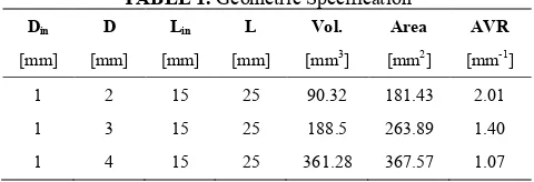
TABLE 1. Geometric Specification
Din D Lin L Vol. Area AVR
[mm] [mm] [mm] [mm] [mm3] [mm2] [mm-1] 1 2 15 25 90.32 181.43 2.01 1 3 15 25 188.5 263.89 1.40 1 4 15 25 361.28 367.57 1.07
2.METHOD
This research work intends to investigate the role of major parameters in micro-combustion process using numerical simulation. These major parameters are area to volume ratios, equivalent ratios of the mixture, and velocities of the mixture passing through the micro-combustor chamber. By varying the values of these major parameters and feeding them into simulation software, and then recordingthe responses of the micro-combustion system such as the mean wall temperature and the temperature profiles along the chambers. For details, the steps required to conduct this research are explain as follows:
2. 1. Development of Micro-combustors In this research, the micro-combustion chamber is designed to give various different geometric characteristic parameters, namely surface area to volume ratio (AVR). The surface area is defined as contact area (interface)
between the mixtures of fuels (burned and unburned) and inside wall of the combustion chamber. The volume is defined as the volume of the mixture (burned and unburned) enclosed by the micro-combustion chamber. Figure 1 shows the basic design of micro-combustors and Table 1 shows various geometric specifications giving different values of AVR (1.07; 1.40; 2.01). This type of micro combustor mostly used in micro-TPV power generator applications because of its simplicity in design and ease of manufacture.
The micro combustor used in this research acts as control volume with a constant pressure. Therefore, there is no work done in the system. Conservationof energy for a constant pressure reactor is shown by Equation (1).
P R p
r H H
Q =
-- , (1)
where Qr,p = Heat reaction or Enthalpy of reaction at constant pressure, HR = Total enthalpy of reactants, and HP= Total enthalpy of products. Negative value of Qr,pindicates heat transfer out of the system to the surroundings and heat of reaction is related to the heat of combustion, Qr,p = -Cc. .
The total enthalpy of Reactants and Products are shown in Equations2 and 3.
(
)
å
D += i R si R i R i
R N h h
H , ˆ0, ˆ , (2)
(
)
å D +
= i P si P i P i
P N h h
H ,
0 ,
, ˆ ˆ (3)
where:
subscript R for reactants and P for products, Ni= number of moles of species i,
0 ˆ
i
h
D = enthalpy of formation at standard condition for
species i,
si
hˆ = sensible enthalpy for species i.
Substituting Equations (2) and (3) into Equation (1) and also at standard temperature and pressure (STP) condition the sensible enthalpy terms drop out for both reactants and products, therefore, the heat released is defined by Equation (4).
å
å
D - D= -i P i P i i R i R i p
r N h N h
Q 0 , , 0 , , 0
, ˆ ˆ (4)
The micro combustor (Figure 1) represent a system with a complete combustion of LPG with air as reactants to form carbon dioxide, water, and nitrogen as products. Thus, a balance stoichiometric kinetic reaction between LPG and air with the assumption of complete combustion may be expressed by Equation (5).
( 2 3.76 2) 3.55 2 4.55 2 21.93 2
12 5 0912 . 0 10 4 4498 . 0 8 3 399 . 0 6 2 041 . 0 4 019 . 0 N O H CO N O H C H C H C H C CH + + ® + + ÷ ÷ ÷ ÷ ÷ ÷ ø ö ç ç ç ç ç ç è æ (5)
In order to study the feasibility of combustion in micro-combustors and determine the relevant factors affecting the micro-combustion, a numerical simulation work on micro flame inside micro-combustor was performed.
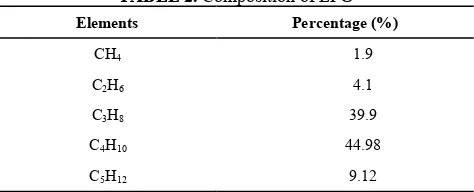
2. 2. Liquid Petroleum Gas (LPG) A. Tripathi, et al. [15] performed a research on burning velocity of LPG/air mixture, and concluded that LPG is a slow burning fuel giving maximum burning velocity (SL) of 0.575 m/s, and it varies depend on the value of equivalent ratio. As a comparation, Ebrahimi, et al. [16] studied about natural gas which consist mainly with methane (CH4 83.5%) having heating value lower than that of gasoline. The composition of LPG used in this experiment is shown in Table 2. LPG is one of hydrocarbon fuels which have interesting properties, such as having a high calorific value and low exhaust gas emissions [17]. Tabejamaat [18] reported, by using appropriate combustion technology would give some advantages such as NOx reduction, energysaving, high efficiency, and low noise.
2. 3. Velocity of the Mixture In order to have position of the premixed flame is floating in between the step and pressure-outlet port of micro-combustor, therefore it is required to set the velocities (u) of the mixture passing through the tube having diameter of D theoretically equal or greater than burning velocities of the mixture. For this research purposes, the velocities of the mixture leaving the step inside the chamber are designed starting from uD= 0.50 m/s until it reaches the possible maximum velocity of each micro combustor. The velocity at this position is considered as a common base velocity of all combustor types and the velocity of the mixture entering the inlet-port could be determined by Equation (6).
D in D
in A u
A
u = (6)
By applying the Equation (6) to the designed starting velocity of the mixture, then the value velocity at the inlet of micro-combustors required to run the simulation can be determined, and it will be increased gradually to run the simulation as shown in Table 3.
TABLE 2. Composition of LPG Elements Percentage (%)
CH4 1.9
C2H6 4.1
C3H8 39.9
C4H10 44.98
TABLE 3. Velocities of Mixture at Inlet Port and Its Equivalence Velocity Inside Chamber [m/s]
AVR=1.07 AVR=1.40 AVR=2.01 Uin UD Uin UD Uin UD
8 0.5 4.5 0.5 2 0.5
10 0.63 5.5 0.61 2.5 0.63
12 0.75 6.5 0.72 3 0.75
14 0.88 7.5 0.83 3.5 0.88
16 1 8.5 0.94 4 1
18 1.13 9.5 1.06 4.5 1.13
20 1.25 11 1.22 5 1.25
22 1.38 13 1.44 5.5 1.38
(a)
(b)
(c)
Figure 2. Temperature contours on micro combustor chamber with AVR=1.07; ɸ=1.0 Uin=13; 17; 21 m/s respectively.
(a)
(b)
(c)
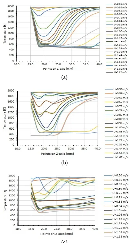
Figure 3. Temperature distribution profile along micro combustor with ɸ=0.6 and a). AVR= 1.07; b). AVR=1.40; c). AVR=2.01
2. 4. Fuel-air Equivalent Ratio ɸ Fuel-Air Equivalent ratio is used to define its quality or state of the mixture. The main effect of variation of this ratio which is taken into account is burning velocities of the mixture. The investigated values of the ratios and its burning velocity are:ɸ=0.6; o.8; 1.0, the laminar burning velocitiesare: 0.475 ; 0.52; and 0.575 m/s, respectively.
Having defined the major parameters, the data are fed into simulation work and the rest of the data required to run this simulation process are kept as constants. The results from these activities are temperature profile and the mean temperature of each set of data.
3. RESULTS AND DISCUSSIONS
After running simulation work, a complete set of solutions are recorded. Main results are images of temperature contour on a symmetry-plane of micro-combustors; the sample of results are shown in Figure 2. This figure visually shows changes in the behavior of combustion process influenced by variation of velocity at the inlet port of the micro-combustor which has a value AVR=1.07 and operated at stoichiometric state.
When mixture at inlet port has velocity of 13 m/s the combustion occurs in the laminar state and temperature is distributed evenly along combustor.By increasing its velocity (17 m/s), the flame begins to shift toward the flame-outlet pressure and lowers the temperature in the rear area of the flame, and at higher speeds will cause the flame to shift further until finally out of the micro-combustor, and then the flame isextinguished.
under investigation. Temperature measurement locations are defined as a series of inline points along micro-combustors starting from the step up to the pressure-outlet and are located in a layer of interfaces between the mixture (burned and unburned) and the combustion chamber wall. The measurement line is divided into ten measurement points that would form very smooth graph of temperature profile. The temperature profiles are taken from various values of Equivalent ratio (Ø), AVR and mixture equivalent velocities (uD). Complete results of temperature profiles are shown in Figures 3, 4, and 5. Figure 3 shows the temperature profiles of the three types of micro combustors operated on an equivalent ratio of Ø = 0.6 with equivalent velocities of the mixture starting from 0.5 m/s. Micro-combustor with AVR=1.07 has very high maximum temperature and distributed uniformly when it is operated on velocities range 0.50 - 0.81 m/s; the next range (0.81 – 1.19 m/s) temperature profile drastically drops toits minimum temperature at position of approximately 5 mm from the step. Beyond these ranges, the flame becomes unstable and starts to move towards the pressure-outlet and finally out of the chamber when the velocity reaches 1.38 m/s.
Micro combustor with AVR=1.40 has high and uniform maximum temperature, when it is operated on velocities range 0.5 - 0.83 m/s; the next range (0.83 –
1.0 m/s) temperature profile drastically drops to its minimum temperature at position of approximately 3 mm from the step.Beyond these ranges, the flame becomes unstable and starts to move towards the pressure-outlet and finally out of the chamber when the velocity is over 1.44 m/s. Micro combustor with AVR=2.01 has high maximum temperature when it is operated on very narrow velocities range of 0.50 - 0.56 m/s. In the next range (0.56 – 0.81 m/s), the temperature profile of each level of velocity slightly drops, and then increases with sinusoidal pattern. Beyond this range, the mean temperature drops drastically andthe flame is extinguished at velocities over 1.31 m/s.
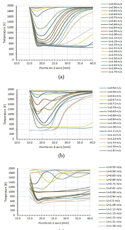
Figure 4 shows the temperature profile of the three types of micro-combustors which are operated on an equivalent ratio of Ø= 0.8 with velocities of the mixture starting from 0.5 m/s. In this combustion conditions, in the micro combustor with AVR = 1.07 uniform temperature distribution occurs in the velocity range of 0.5 - 0.75 m/s; for the next range (0.75 - 1.31 m/s) temperature profile drastically drops toits minimum temperature at position ofapproximately 8 mm from the step. Beyond these ranges, the flame becomes unstable and starts to move towards the pressure-outlet, and finally out of the chamber when the velocity reaches 1.38 m/s.
Micro-combustor with AVR=1.40 has high and uniform maximum temperature when it is operated on velocities range of 0.5 - 0.83 m/s; the next range (0.83 –
0.94 m/s) temperature profile drastically drops to its
minimum temperature at position of approximately 7 mm from the step. Beyond these ranges, the flame becomes unstable and starts to move towards the pressure-outlet and finally out of the chamber when the velocity is over 1.44 m/s.
Micro combustor with AVR=2.01 has high maximum temperature when it is operated on very narrow velocities range of 0.50 - 0.56 m/s. In the next range (0.56 – 0.81 m/s), the temperature profile of each level of velocity slightly drops and then increases with a sinusoidal pattern. Beyond this range, the mean temperature drops drastically and the flame is extinguished at velocity over 1.31 m/s.
Figure 5 shows the temperature profile of the three types of micro combustors which are operated on an equivalent ratio of Ø= 1.0 (stoichiometric) with velocities of the mixture starting from 0.5 m/s.
(a)
(b)
(c)
This shows the characteristics of the micro-scale combustion which is not much different from the characteristics shown in Figures 3 and 4, except for a little difference in operating velocity range shift of the mixture to produce a temperature distribution profile. This suggests that the profile of temperature distribution is not significantly affected by the value of equivalent ratio. It is clearly shown on Figure 3(c) that combustion does not occur at velocity of 1.38 m/s but by increasing the equivalent ratio, the combustion takes place at the same velocity on Figures4(c) and 5(c).
By observing temperature profiles with various mixture velocitis inside all micro-combustors under investigation, these clearly show that the increase of the velocity will lower the temperature of combustion process because the residence time of the mixture will be shorter by the raise of velocity mixture. When the resident time is not sufficient, then a complete combustion does not take place in the combustor, unburned fuel will quench the combustion process and finally extinguish the flame. Two other parameters seen clearly affect the combustion process inside micro combustors; equivalent velocity (uD) clearly governs the temperature profile starting from the value of laminar burning velocity of the mixture which produces a uniform temperature distribution. By increasing equivalent velocity, uniformity of temperature profile becomes distracted and eventually flame extinction occurs in all types of micro combustors. The AVR is another parameter which obviously affects the temperature profile, because in this case the increase of the AVR can be interpreted as narrowing the diameter of the micro combustor. So, it can be concluded that the collaboration between variations of velocity and diameter affect the changes of Reynolds number that classify the types of flow inside combustors.
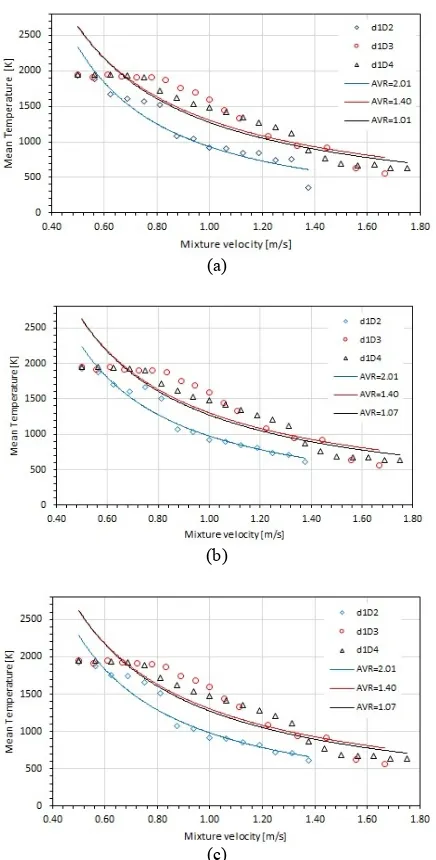
3. 2. Mean Temperature (Tm) The mean temperature is defined as the average value of all the temperature measurements along temperature contours generated by the simulation activity. All micro combustors have a common location of step which governs the micro combustion processes, i.e. mostly the combustions take place from the step upto the exit port. Thus, the temperature reading points (10 points) on the images of temperature contour are located between the step and exit port, and then the temperature data are obtained from these points. The mean temperature data are plotted versus the velocities mixture, then an appropriate trend line inserted into the graph; finally Figure 6 (a), (b), and (c) are obtained.Figure 6 clearly shows that the mean temperature (Tm) of the wall is strongly influenced by the supply velocity (uin) of fuel-oxidant mixture; the higher the velocity of the mixture, then the average temperature of the combustion process in a micro combustor decreases until finally the flame outage.
(a)
(b)
(c)
Figure 5.Temperature distribution profile along micro combustor with ɸ=1.0 and a). AVR= 1.07; b). AVR=1.40; c). AVR=2.01
This situation can occur due to the increase of velocity,which causes the residence time of the mixture become shorter, so that it does not burn completely during its passage through the micro combustor.
(a)
(b)
(c)
Figure 6. The effect of mixture velocity and AVR to the mean temperature of micro-combustor, with equivalence ratio of a). ɸ=0.6; b). ɸ=0.8; c). ɸ=1.0
3. 3. Empirical Equation Further investigation ofFigure 6, there are equations of the relationship between the mean temperature and velocity for a certain value of AVR and equivalent ratio (Ø). For combustion process with Ø =0.6 and AVR=1.07; 1.40, and 2.01 gives equation of relationship between mean temperature and velocity as shown by Equation (7), (8), and (9) respectively:
046 . 1 1272
-= D
m u
T (7)
046 . 1 11304
-= D
m u
T (8)
327 . 1 1931
-= D
m u
T (9)
For combustion process with Ø =0.8 and AVR=1.07; 1.40, and 2.01 gives equation of relationship between mean temperature and velocity as shown by Equations(10), (11), and (12) respectively:
045 . 1 1272
-= D
m u
T (10)
007 . 1 11303
-= D
m u
T (11)
198 . 1 977
-= D
m u
T (12)
For combustion process with Ø =1.0 and AVR=1.07; 1.40, and 2.01 gives equation of relationship between mean temperature and velocity as shown by equation 13, 14, and 15, respectively:
045 . 1 1272
-= D
m u
T (13)
008 . 1 11302
-= D
m u
T (14)
224 . 1 981
-= D
m u
T (15)
By observing Equations (7)-(15), shows that the equivalent ratio (Ø) does not significantly affect the mean temperature (Tm) of the micro combustion, but parameter AVR significantly affects the mean temperature (Tm) of a micro combustion.
Premixed-combustion simulation inside cylindrical micro combustors having different geometric design represented by different values of area to volume ratio (AVR) has been performed in present study. The simulation study on temperature distribution profiles and mean temperature profiles of micro combustion on a series of micro combustors was carried out. The temperature of combustion along micro combustor chamber was read from temperature contour of its symmetrical plane. The effect of Area to Volume Ratio (AVR), flow velocity (uD), and fuel-air equivalent ratio (ɸ) were investigated. Based on the observation of the temperature profile graph can be noticed clearly that the higher value of AVR, the greater tendency to lower the mean wall temperature and leads to extinguish the flame. The higher AVR value means the higher the surface area of the micro combustor.Therefore, the amount of heat loss through the wall is also greater, and will quench the flame. From the analysis of temperature profile, it is found that all micro combustors that have AVR of 1.07, 1.40, and 2.01, give the maximum and uniformly distribute temperature when the flow velocity in the range of: 0.50 - 0.81 m/s; 0.5 - 0.83 m/s, and 0.50 - 0.56 m/s respectively. It means there is a common
velocity range that result a high and uniform temperature distribution, i.e. around laminar burning velocity of the mixture (0.50 – 0.56 m/s). Beyond these ranges, the flame become unstable and start to move towards the pressure-outlet and finally out of the chamber or flame isextinguished. It is interesting that micro combustor with AVR of 1.07 and 1.40 there is no significant different in the mean temperature profile, but on micro combustor with AVR of 2.01 there is very significant different which may lead to future study on this topic with narrower range (1.40 – 2.01).
1. LoughboroughUniversity, "An introduction to MEMS (Micro-Electromechanical systems, prime faraday partnership, loughborough", (2002).
2. Peirs, J., Reynaerts, D. and Verplaetsen, F., "Development of an axial microturbine for a portable gas turbine generator", Journal of Micromechanics and Microengineering, Vol. 13, No. 4, (2003).
3. Kyritsis, D.C., Roychoudhury, S., McEnally, C.S., Pfefferle, L.D. and Gomez, A., "Mesoscale combustion: A first step towards liquid fueled batteries", Experimental Thermal and Fluid Science, Vol. 28, No. 7, (2004), 763-770.
4. Yang, W., Chou, S., Shu, C., Xue, H. and Li, Z., "Development of a prototype micro-thermophotovoltaic power generator",
Journal of Physics D: Applied Physics, Vol. 37, No. 7, (2004), 1017-1020.
5. Bermel, P., Ghebrebrhan, M., Chan, W., Yeng, Y.X., Araghchini, M., Hamam, R., Marton, C.H., Jensen, K.F., Soljacic, M. and Joannopoulos, J.D., "Design and global optimization of high-efficiency thermophotovoltaic systems",
Optics Express, Vol. 18, No. 103, (2010), A314-A334. 6. Sitzki, L., Borer, K., Schuster, E., Ronney, P.D. and Wussow,
S., "Combustion in microscale heat-recirculating burners", in The Third Asia-Pacific Conference on Combustion, Seoul, Korea. Vol. 6, (2001), 11-14.
7. Jacobson, S.A. and Epstein, A.H., "An informal survey of power mems", in The international symposium on micro-mechanical engineering. Vol. 12, (2003), 513-519.
8. Wenming, Y., Siawkiang, C., Chang, S., Hong, X. and Zhiwang, L., "Effect of wall thickness of micro-combustor on the performance of micro-thermophotovoltaic power generators",
Sensors and Actuators A: Physical, Vol. 119, No. 2, (2005), 441-445.
9. Deng, W., Klemic, J.F., Li, X.,, Reed, M.A. and Gomez, A., "Liquid fuel micro-combustor using micro fabricated multiplexed electrospray sources", Proceedings of the Combustion Institute, Vol. 31, No. 2, (2007), 2239-2246. 10. Pan, J., Huang, J., Li, D., Yang, W., Tang, W. and Xue, H.,
"Effects of major parameters on micro-combustion for thermophotovoltaic energy conversion", Applied Thermal Engineering, Vol. 27, No. 5, (2007), 1089-1095.
11. Yang W.M. and Chou S.K., L.J., "Micro thermo-photovoltaic power generator with high power density", Applied Thermal Engineering, Vol. 29, (2009), 3144-3148.
12. Li Z.W., Chou S.K., Shu C., Xue H. and Yang W.M., "Characteristics of premixed flame in micro-combustors with different diameters", Applied Thermal Engineering, Vol. 25, (2004), 271-281.
13. Yang, W., Chou, S., Shu, C., Xue, H., Li, Z., Li, D. and Pan, J., "Microscale combustion research for application to micro thermophotovoltaic systems", Energy Conversion and Management, Vol. 44, No. 16, (2003), 2625-2634.
14. Yang, W., Chou, S., Shu, C., Li, Z. and Xue, H., "Combustion in micro-cylindrical combustors with and without a backward facing step", Applied Thermal Engineering, Vol. 22, No. 16, (2002), 1777-1787.
15. Tripathi, A., Chandra, H. and Agrawal, M., "Effect of mixture constituents on the laminar burning velocity of lpg-co 2-air mixtures", ARPN Journal of Engineering and Applied Sciences, Vol. 5, No. 5, (2010).
16. Ebrahimi, R. and Mercier, M., "Experimental study of performance of spark ignition engine with gasoline and natural gas", International Journal of Engineering, Vol. 24, (2010), 65-74.
17. Savadkouhi, L., Sohrabi, A. and Babaei, R., "Research and assessment of applying dimethyl ether “dme” extracted from natural gas “NG”, on diesel engine as a clean fuel (technical note)", International Journal of Engineering-Transactions B: Applications, Vol. 20, No. 2, (2007), 193-201.
18. Tabejamaat, S., "Numerical study of reduction of nox emission by high temperature air combustion technology", International Journal of Engineering-Transactions B: Applications, Vol. 16, No. 3, (2003), 301– 310
.
Simulation Study: The Role of Area to Volume Ratio and Key Parameters in
Cylindrical Micro Combustors
A. R. Wirawana,b, S. Sudjitoa, W. Slameta, W. Dennya
aPost Graduate of Mechanical Engineering, University of Brawijaya, Malang, Indonesia bDepartment of Mechanical Engineering, the State Polytechnic of Malang, Malang, Indonesia
P A P E R I N F O
Paper history:
Received 10 March 2014
Received in revised form 19 July 2014 Accepted 13 November 2014
Keywords:
Premixed Micro-combustion Micro Combustor Area to Volume Ratio Temperature Distribution Numeric Simulation Premixed Flame هﺪﯿﮑﭼ ﻣ ﻪﻈﻔﺤ ي ﺰﯾر هﺎﮕﺘﺳد زا ﯽﮑﯾ قاﺮﺘﺣا ﮏﭼﻮﮐ يﺎﻫ
ﻞﯾﺪﺒﺗ ﺪﻨﻧﺎﻣ تﻻﻮﺼﺤﻣ ترﺪﻗ ﻪﺑ ﺎﻣﺮﮔ تﻮﺑور ﺰﯾر
-ﺎﻫ تﻮﻧ يﺎﻫﺮﺗﻮﯿﭙﻣﺎﮐ ،
هﺎﮕﺘﺳد ﺮﯾﺎﺳ و ﯽﯾاﻮﻫوﺮﮑﯿﻣ ﻪﯿﻠﻘﻧ ﻞﯾﺎﺳو ،كﻮﺑ ﺖﺳا ﮏﭼﻮﮐ سﺎﯿﻘﻣ يﺎﻫ
. ﯿﻣ قاﺮﺘﺣا ﻪﻈﻔﺤﻣ ﻪﭼرﺎﭙﮑﯾ وﺮﮑ
هﺪﺷ ﺎﺑ ﻢﺘﺴﯿﺳ
ﮏﯿﯾﺎﺘﻟوﻮﺗﻮﻓ
( TPV )
ﻦﯾا قﺮﺑ ﺰﯾر هﺎﮕﺘﺳد ار ﺎﻫ ﯽﻣ ﻦﯿﻣﺎﺗ ﮐ ﺪﻨ . ﻪﻌﺳﻮﺗ ي ﻣ ﻪﻈﻔﺤ ي ﺰﯾر ﺎﺑ ترﺪﻗ ﻊﺒﻨﻣ ﮏﯾ ناﻮﻨﻋ ﻪﺑ قاﺮﺘﺣا
دﻮﺧ ﯽﺗاذ يﺎﯾاﺰﻣ ﻪﺑ ﻪﺟﻮﺗ ﻞﻣﺎﺷ
ﺐﯾاﺮﺿ مﺮﺟ و تراﺮﺣ لﺎﻘﺘﻧا ،ﺮﺗﻻﺎﺑ يژﺮﻧا ﯽﻟﺎﮕﭼ ﺮﺘﺸﯿﺑ
هﺎﺗﻮﮐ ژرﺎﺷ نﺎﻣز و ﻪﺴﯾﺎﻘﻣ رد ﺮﺗ
يﺮﺗﺎﺑ ﺎﺑ ﺎﻫ ﯽﯾﺎﯿﻤﯿﺷوﺮﺘﮑﻟا ي ﺶﻫوﮋﭘ ﻪﺟﻮﺗ درﻮﻣ
ﺖﺳا ناﺮﮔ . ﺶﻫوﮋﭘ ﻦﯾا رد ﺪﯾﺪﺟ مﻮﻬﻔﻣ ﮏﯾ
ﺰﯾر قاﺮﺘﺣا ﺑ ﯽﻓﺮﻌﻣ ﺎ
ﺖﺳا هﺪﺷ ﻒﯿﺻﻮﺗ ﺪﯾﺪﺟ تﺎﺣﻼﻄﺻا . ﺖﺒﺴﻧ ﺮﺛا ﻪﺑ ﺖﺣﺎﺴﻣ ﻢﺠﺣ ) AVR ( رﻮﻈﻨﻣ ﻪﺑ ﯽﺣاﺮﻃ دﺮﮑﻠﻤﻋ ﻦﯾﺮﺘﻬﺑ ندﺮﮐ اﺪﯿﭘ
ﻣ ﻪﻈﻔﺤ ي ﺰﯾر ﺖﻓﺮﮔ راﺮﻗ ﻪﻌﻟﺎﻄﻣ درﻮﻣ قاﺮﺘﺣا . نﺎﮑﻣا ﯽﻨﻓ ﯽﺠﻨﺳ ﻣ ﻪﻈﻔﺤ ي ﺰﯾر ﺘﺣا ﯽﻌﻗاو ﺶﯾﺎﻣزآ زا ﻞﺒﻗ هﺪﺷ ﯽﺣاﺮﻃ قاﺮ زا
ﻖﯾﺮﻃ ﺪﺷ مﺎﺠﻧا يزﺎﺳ ﻪﯿﺒﺷ .
دراد دﻮﺟو ﺮﺿﺎﺣ ﻪﻌﻟﺎﻄﻣ رد يﺪﯿﻠﮐ ﺮﺘﻣارﺎﭘ ﻪﺳ :
ﺖﺒﺴﻧ ﻪﺑ ﺖﺣﺎﺴﻣ ﻢﺠﺣ ) AVR ( نﺎﯾﺮﺟ ، طﻮﻠﺨﻣ ﺖﻋﺮﺳ ) U ( و ، ﺖﺒﺴﻧ لدﺎﻌﻣ ﺖﺒﺴﻧ ار ﺖﺧﻮﺳ ﻪﺑ اﻮﻫ )
Ø .( زا يﺮﯾوﺎﺼﺗ ﺶﯾﺎﻣزآ ﻦﯾا ﯽﻠﺻا ﺞﯾﺎﺘﻧ ﻧ
يﺎﻫرادﻮﻤ
و ﺎﻣد ﻊﯾزﻮﺗ اﺮﺣ
تر ﺖﺳا ﻦﯿﮕﻧﺎﯿﻣ .
نﺎﺸﻧ ﻪﻌﻟﺎﻄﻣ ﻦﯾا هداد
ﺖﺳا هﺮﺘﺴﮔ ﻪﮐ ي دراد دﻮﺟو طﻮﻠﺨﻣ نﺎﯾﺮﺟ ﺖﻋﺮﺳ زا ﯽﺻﺎﺧ ) 0.50 -0.56 ﺮﺘﻣ / ﻪﯿﻧﺎﺛ ( ﺮﺠﻨﻣ ﻪﮐ ﻪﺑ ﻊﯾزﻮﺗ يﺎﻣد ﻻﺎﺑ ي ﻦﯾﺮﺘﻬﺑ ﻦﯿﮕﻧﺎﯿﻣ ﻦﯿﻨﭽﻤﻫ و ﺖﺧاﻮﻨﮑﯾ يﺎﻣد
قاﺮﺘﺣا ﺪﻨﯾآﺮﻓ ﯽﻣ
دﻮﺷ .
يزﺎﺳ ﻪﯿﺒﺷ رﺎﮐ ﻦﯿﻨﭽﻤﻫ ﯽﻣ ﺪﻧاﻮﺗ هﺮﺘﺴﮔ ي صﺎﺧ زا راﺪﻘﻣ AVR ) 1.40 -2.01 ( هﺪﻨﯾآ رد ﺮﺘﺸﯿﺑ تﺎﻘﯿﻘﺤﺗ ﻪﺑ زﺎﯿﻧ ﻪﮐ ار دراد
دزﺎﺳ ﺺﺨﺸﻣ .
![TABLE 3. Velocities of Mixture at Inlet Port and Its Equivalence Velocity Inside Chamber [m/s]](https://thumb-us.123doks.com/thumbv2/123dok_us/228881.2017454/4.595.58.284.422.742/table-velocities-mixture-inlet-equivalence-velocity-inside-chamber.webp)