A New Wireless Sensor Network Scheme to Provide
Quality of Service (QoS) for Smart Grid Applications
Fawaz Alassery
Department of Computer Engineering, College of Computers and Information Technology, Taif University, Saudi Arabia
Abstract
Wireless Sensor Networks (WSNs) has been utilized in a wide range of smart grids applications due to their capabilities to monitor environmental phenomena or connect the physical world to the virtual word. WSNs include large number of sensor nodes which obtain data about physical phenomena that is difficult to obtain in more conventional ways. For smart grid applications, supporting the Quality of Service (QoS) is the main requirement from WSNs, such as transmitting delay-critical data from smart grid assets as fast as possible or identifying priority packets which need to be transmitted before any other periodic packets and hence reducing the collision rate. At the same time, WSNs need to provide the required QoS for a long time (e.g. months or years) using the limited resources of the network (e.g. limited energy resources or channel bandwidth). Meeting such a goal requires a remarkable design for WSNs protocols in order to satisfy the requirements of delay/priority critical smart grid applications. In this paper, we propose a suit of novel WSNs Medium Access Control (MAC) protocol which aims to provide QoS in terms of low transmitting delay for packets and supporting the priority packets over the network for smart grid applications. Our proposed MAC protocol is called Delay and Priority MAC protocol (or DPMAC) for smart grid applications based on WSNs. DPMAC protocol is based on the delay estimation and priority packets that are defined by the application layer of the smart grid application and the network conditions. Our comprehensive performance analysis shows how the proposed DPMAC protocol can achieve low end-to-end delay and lower collision rate in comparison with the well-known IEEE 802.15.4 MAC protocol which is used extensively in literature to provide the QoS for smart grid applications.Keywords
Smart grid applications protocols, WSNs MAC protocols, Supporting QoS in smart grid, Priority MAC protocols, Delay-aware smart grid applications1. Introduction
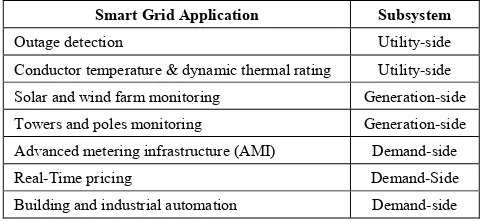
With the recent advances in wireless communication technologies, WSNs have gained great attention to realize efficient and low cost monitoring systems for smart grid applications [1]. In monitoring systems, wireless sensor nodes have been used to improve efficiency, reliability, availability and many other QoS aspects for smart grid applications [2]. As shown in Table 1, WSNs-based smart grid applications include outage detection, conductor temperature and dynamic thermal rating, solar and wind farm monitoring, towers and poles monitoring, advanced metering infrastructure (AMI) and real-time pricing and Building and industrial automation [3].
However, due to RF interference, equipment noise, fading effects and obstructions in smart grid environments, testing the performance of many smart grid applications may result in high packets error rates as well as variable
* Corresponding author:
falasser@tu.edu.sa (Fawaz Alassery)
Published online at http://journal.sapub.org/jwnc
Copyright © 2016 Scientific & Academic Publishing. All Rights Reserved
links qualities. Therefore, the realization of WSNs-based smart grid applications is mandatory in order to design WSNs MAC protocols that can meet the QoS required by the smart grid applications [5].
protocols in smart grid environments for the power distribution system monitoring and customer applications, IEEE 802.15.4 and IEEE 802.15.1 MAC do not support QoS and typically have a short propagation distance.
The QoS required for smart grid applications can be defined as the capability of proposed techniques/protocols to ensure the monitoring data, the emergency response and control command to be reliably delivered within required time frame, but would not be affected by the number of users in the network and their data traffic [5]. Thus, there are two main aspects need to be considered when designing WSNs MAC protocols for smart grid applications, namely, the delay when transferring the packets and the priority to be added to the emergency packets. In fact, these two parameters will be considered in our propose DPMAC protocol in this paper.
Hence, the main contribution of this paper is the following:
• We enhance the performance of WSNs for smart grid applications. In particular, we propose a suit of novel Daly and Priority MAC protocol (or DPMAC) for WSNs in order to provide QoS requirements of smart grid applications. In DPMAC, if the delay estimation performed by the application layer of a smart grid application doesn't meet the requirements to provide the required QoS (i.e. the delay estimation is higher than a pre-specified delay threshold), then the channel access by a sensor node will be controlled by reducing the Clear Channel Assessment (CCA) duration and giving a higher priority for such a node to get access to the communication channel. Hence, DPMAC protocol considers the delay estimation as well as the priority with fairness that neighboring nodes will contend fairly to access to the channel.
• We compare the performance of DPMAC protocol against well-known QoS supporting schemes which are proposed in literature. In particular, we study the performance of DPMAC against IEEE 802.15.4 protocol in terms of the end-to-end delay, the energy consumption of WSNs, packets delivery ratio and the collision rate.
• Finally, we apply our propose DPMAC protocol on real smart grid applications in order to demonstrate the advantages of our protocol. Here, we pick two smart grid applications from Table 1, namely, poles monitoring and real time pricing and shows how our propose DPMAC achieve the required QoS requirements of these smart grid applications.
The rest of this paper is organized as follows. In section 2, we discuss some related works. In section 3, we explain our system description. In section 4, we describe the delay estimation model of our proposed DPMAC protocol, and we detail our proposed DPMAC protocol. The performance evaluation of DPMAC protocol and the comparison of DPMAC against the existing QoS schemes are presented in section 5. In addition, we investigate the performance of our
DPMAC protocol in real smart grid application. Finally, the conclusion of the paper is presented in section 6.
Table 1. WSNs-based smart grid applications
Smart Grid Application Subsystem
Outage detection Utility-side
Conductor temperature & dynamic thermal rating Utility-side Solar and wind farm monitoring Generation-side
Towers and poles monitoring Generation-side
Advanced metering infrastructure (AMI) Demand-side
Real-Time pricing Demand-Side
Building and industrial automation Demand-side
2. Related Works
The use of WSNs to support QoS for smart grid applications has been studied in literature. For example, using WSNs for the monitoring purposes in smart grid applications is studied in [6-8]. The challenges and opportunities of using WSNs in smart grid application is discussed extensively in [6]. In [7], authors applied wireless multimedia sensors for monitoring purposes in smart grid environment. Using WSNs for reducing and controlling homes electricity consuming is proposed in [8, 9]. Authors in [9], proposed Time of Use (TOU)-aware energy management scheme to reduce the peak load of smart grid applications based on WSNs. the authors studied the impact of their proposed scheme on the consumer peak load at smart homes, and their proposed scheme shows a significant saving around 30%.
The performance of WSNs in smart grid environment is elaborated in in some researches. For examples, authors in [10] studied various efficient routing schemes in WSNs for the purpose of providing QoS in smart grid applications. The authors reach to the conclusion about the potential areas WSNs can be deployed for efficient operation monitoring and control of the smart grid applications such as electric transportation, distribution energy resources and storage, etc. Authors in [11] proposed Fi-WSN (Fiber-Wireless Sensor Network) gateway which allows packets prioritization and supporting QoS of FTTX users in smart grid environment. Authors in [12] proposed adaptive QoS scheme (AQoS) and an adaptive guaranteed time slot (AGTS) allocation scheme for IEEE 802.15.4-based WSNs used in high traffic intensity smart grid monitoring applications. Their performance evaluation showed an effective reduction in end-to-end delay and the flexibly tune the GTS to provide the required QoS for smart grid application.
their XLP protocol against some existing cross-layer protocols of WSNs. In addition, authors in [14], developed XLP protocol which integrates physical, MAC, routing, as well as transport layer functionalities into a unified communication framework. The XLP protocol is compared against current state of art cross-layer protocols in WSNs. In [15], authors integrated MAC and routing layer functionalities in order to rout a packet from one hop to next based on a weighted progress factor, which considers the energy efficiency. Cross-layer optimization solutions for power control at the physical layer and the congestion control at the transport layer are proposed in [16-17]. In [18], authors integrated routing, MAC and link layer optimization to efficient design of a WSN framework. The practical implementation is not feasible in the paper as well as the transport layer functionalities such as the congestion control. In [19], scheduling and cross-layer congestion control algorithm for WSNs is proposed, and the performance evolution shows incredible improvements in the network performance, however, the paper focus only on two layers of the cross-layer design which are the data link and the transport layers.
The QoS is often defined as an objective measurement of the services delivered by the network expressed in terms of bandwidth, delay, reliability and jitter. In other words, the QoS aimed to deliver high priority packets to the destination with high reliability and low delay. Supporting QoS for WSNs is also investigated in literature and several QoS-aware MAC and routing protocols were proposed. However, they only focus on a few QoS parameters such as the delay [20] and the reliability [21]. Authors in [22] proposed a mechanism that reduces the number of CCA in order to deliver high priority packets to a destination in event-monitoring networks. Some works focus on reducing the duration of CCA instead of reducing the number of CCA in order to lower end-to-end delay and add priority to some packets in WSNs such as the proposed shame in [23]. The impact of CCA on the performance of energy constrained wireless networks are discussed in [24-26].
3. System Description
Our system description is based on assuming a WSN which aims to monitor delay-critical smart grid environment. We assume sensor nodes are distributed randomly in sensing filed, and some nodes are required to deliver high priority packets to a sink node (a receiver) with a minimum end-to-end delay (i.e. We distribute 100 sensor nodes and one sink node in the sensing filed which is set to be 500 × 500 m). We also test our proposed DPMAC protocol over different network conditions such as path-loss effects and shadowing deviations. In addition, we assume that every node sends a constant bit rate and the packets follow the shortest communication path from one node to the next until they arrive to the sink node. The transmission rang of a sensor node is set to be 30 m. Every sensor node
starts sending their packets to the sink node with initial transmission power that decreases every time a node become active for transmission and sending. So, all sensor nodes can reach the sink node. Also, the noise factor is assumed to be a constant number in our system model. Moreover, a delay threshold of our proposed DPMAC protocol is set in every sensor node to determine the possibility to access to the communication channel (more details of the delay threshold are discussed in section 5).
Therefore, in our system model if a packet arrive to a sensor node and the delay estimation performed by the application layer of a smart grid application ( i.e. we test different delay requirements for specific smart grid applications) doesn't meets the requirements to provide the required QoS (i.e. the delay estimation as will be explained in section 4 is higher than a pre-specified delay threshold which is set in each sensor node), then the channel access by a sensor node will be controlled by reducing the CCA duration and giving a higher priority for such a packet to get access to the communication channel. Hence, DPMAC protocol considers the delay estimation as well as the priority with fairness that neighboring nodes will contend fairly to access to the channel.
4. Algorithm Description
In this section we first analyze the delay estimation model of our proposed DPMAC protocol and derive all related numerical equations. After that, we detail DPMAC protocol and discuss the procedures on how it works.
4.1. DPMAC Delay Estimation Mechanism
The delay estimation model of our proposed DPMAC protocol follows the same analysis described in [27] for the slotted CSMA/CA MAC protocol of the beacon-enabled mode of the well-known IEEE 802.15.4. Authors in [27] derived accurate as well as approximate nonlinear equations that represent the mathematical analysis for the reliability, the delay and energy estimation models. In this subsection we will focus on the approximate delay estimation model (the accurate estimation model is difficult to be applicable in limited energy resources networks such as WSNs) to propose DPMAC protocol that considers the minimum end-to-end delay as well as the prioritization aspect in order to content the access to the communication channel. So, rather than solving nonlinear equations as the case in accurate estimation model, the approximate estimation model is based on local measurements to evaluate the end-to-end delay.
1 1
,0, 0,0,0
0 0
1 1
1 1
m n m n
i j i j x y b b x y + + = = − − = − −
∑ ∑
(1)In equation (1), m and n are the backoff counter and the retransmission stage, respectively. In addition, b0,0,0 is the
approximate stationary distribution of the Markov chain which can be given as:
(
) (
)
1 1 2 2 2 0 2 0 0 , 0 , 0 1 ) 1 ) 1 ( ) 1 ( ( ) 1 ( ) 1 ( ) 1 ( ) 2 1 ( 2 − − + + − − + + + + + + ≈ n c c s x P x P K y x L y x Wb (2)
Where W0=2minBE (i.e. back-off exponent (BE)), LSis the
time period of successful transmission and it can calculated as LS= L+ tACK+LACK+IFS. Here, L is the total length of packet including overhead and payload, tACK is ACK waiting time, LACK is the length of ACK frame, IFS is Inter-Frame Spacing, K0= L0 Pi / 1-Pi ; where L0 is the idle
state length and Pi is the probability of going back to the idle
state. Moreover, in equation (1), x and y are defined as follows:
x=α + (1-α)β (3) y= PC(1-
x
m+1) (4) As we see in the equations (1), the probability τ depends on the probability PC , which is the probability that at leastone of the N – 1 remaining nodes transmits in the same time slot, where N is the total number of sensor nodes which we assume in our system model (i.e. Section 3) to be 100 nodes. If all sensor nodes transmit with probability τ, then the probability that at least one of the N – 1 remaining nodes transmits in the same time slot (PC) can be given as:
1 ) 1 ( 1− − −
= N
C
P τ (5)
Now, we derive the busy channel probabilities α and β. The probability that a first carrier sensing is busy (α) is given as:
2 1 α α
α= + (6) where
α
1 is the probability of finding channel busy duringthe first carrier sensing due to data transmission, and
α
2 is the probability of finding the channel busy during first carrier sensing due to ACK transmission.α
1 andα
2 canbe calculated as follows:
(
)
(
τ)
(
α) (
β)
α = 1− 1− −1 1− 1−
1
N
L (7)
(
)
(
τ)
(
α) (
β)
τ τ τ α − − − − − − − = − − 1 1 1 1 ) 1 ( 1 ) 1( 1 1
2 N N
N ACK N
L (8)
The probability that the second carrier sensing is busy (β) can be calculated as:
(
)
(
)
(
)
(
)
1 1 1 1 1 2 1 1 1 − − − − + − − − + − −= NN NN
N N τ τ τ τ τ τ
β (9)
Now, the average delay can be approximated as:
[ ]
D =PTD∂ ~ (10)
where
[
(
) (
)
]
( 1)10 ... ∈ℜ + ×
= T n
t n r t
r A A P A A
P
P
[
]
( 1)10
...
∈
ℜ
+ ×=
T nn
d
d
D
(
j
1
)
[
T
~
]
jT
T
d
j=
s+
c+
+
∂
In the last equation, Ts is is the time durations of
successful packets transmissions, Tc is the time durations of
collided packet transmissions, and ∂
[ ]
T~ is the approximation of the average backoff period which can be given by:[ ]
T~ 2S (1 P~TT)b +
=
∂ (11)
where
~
=
[
~
(
0) (
...
~
)
]
∈
ℜ
(m+1)×1T t m t
P
B
B
B
B
P
P
[
]
( 1)10
...
∈
ℜ
+ ×=
T mm
t
t
T
(
)
4 1 3 12 1− 0+ −
= + W i
ti i
(
j t)
r A A
P represents the occurrence of successful packet transmission at time j+1 given that at time j, the transmission is unsuccessful (i.e.
A
j). The occurrence of successful packet transmission within n attempts is (A
t). It can be calculated as follows:(
)
(
)
1 1 1 1 )) 1 ( ( 1 ) 1 ( 1 1 ) ( + + + + − − − − −= m n
c j m j c m c t j
r P x
x P x P A A
P (12)
(
BiBt)
P~ represents the occurrence of a busy channel for the ith time and then an idle channel at the i+1th time (i.e.
i
B
)
the successful sensing event in m attempts is (i.e.B
t) It can be calculated as follows:(
)
0
max( ,(1 ) ) max( ,(1 ) )
i
i t m
k
k
P B B α α β
α α β = − = −
∑
(13)In equation (12), Pc is the collision probability per sending attempt and 1−xm+1 is the probability of successful channel accessing within the maximum number of m backoff stages. This analysis of estimated delay has been proposed in [27] and used in our PDMAC protocol which is described in next subsection.
4.2. Algorithm Description of DPMAC Protocol
As explained in section 3 that we assume a WSN where sensor nodes are distributed randomly in the sensing filed of a smart grid environment, and packets are delivered to a sink node for further processing and communication. Some of these packets are marked as higher priority packets which need to be delivered as fast as possible with minimum end-to-end delay.
the physical layer of the smart grid application with the lower layers such as MAC and physical layers. In other words, if packets collected by the application layer of a smart grid application marked as higher priority packets, the delay estimation model for those packets which is described in the previous subsection need to be considered in each node of the WSN in order to facilitate the transmission of the packets to the required sink node with a minimum end-to-end delay. Thus, sensor nodes will estimate the delay required by a specific smart grid application and make a decision on how to control the lower MAC layer by reducing the CCA duration which ensure that the packets will be delivered quickly and delay requirements of a smart grid application will be met.
To be more specific, if a packet arrive to a sensor node and the delay estimation performed by the application layer of a smart grid application doesn't meet the requirements to provide the required QoS (i.e. the delay estimation is higher than a pre-specified delay threshold which is set in each sensor node), then the channel access by a sensor node will be controlled by changing the parameters of lower MAC and physical layers. So, once packets arrive to the MAC layer, it will request the physical layer to reduce the duration of the CCA (i.e. the symbol periods will be reduced from 8 symbols (i.e. 128µs) to 4 symbols (i.e. 64µs) or 2 symbols (i.e. 32µs )). In response to the request made by the MAC layer, the physical layer will sense the communication channel either in half of the CCA duration (i.e. 8 symbol periods) or quarter of the CCA duration (i.e. 4 symbol periods). The selection between the half and the quarter of CCA duration is based on the distance between a sensor node and the receiver (sink) node.
In PDMAC protocol, the algorithm starts with testing evaluated packets of the application layer of a smart grid application and deciding their priority (ρ) based on a pre-specified priority threshold
(
ρ
th)
. If the priority of a packet (ρ) which is specified in the application layer is greater than the pre-specified priority threshold(
ρ
th)
, then the delay estimation model which is described in previous subsection will be invoked (i.e. in equation 10). If the delay estimation model is greater than a pre-specified delay threshold(
t
th)
which is vary based on the smart grid application, then the physical layer will check the distance between the sensor node and the sink node, if the sensor node is located in a coordination(
C
a,b)
which is close to the sink node(
i.e. based on a pre-specified distance threshold(
d
th)
)
, the MAC layer will request the physical layer to sense the channel quarter of the CCA duration since there are many nodes which send their packets in this area of the sensing filed and the traffic load is high. Also, if the sensor node is located in a coordination(
C
a,b)
which is greater than a pre-specified distance threshold(
d
th)
, then MAC layer will request the physical layer to sense the channel half of the CCA duration since nodes in this area are located far fromthe sink node and the traffic load is low. If the delay estimation model is lower than a pre-specified delay threshold
(
t
th)
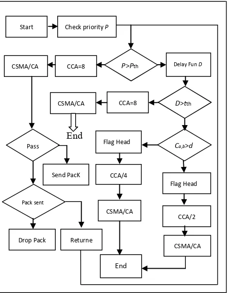
, then the algorithm will not change theduration of the CCA periods (i.e. 8 symbol periods) and physical layer will follow the regular procedures of CSMA-CA MAC protocol when sending packets to the destination (sink node). Also, If the priority of a packet which is specified in the application layer is lower than the pre-specified priority threshold (ρ), then the algorithm will not change the duration of the CCA periods, and the CSMA-CA MAC protocol will be utilized to either successfully transmitting packets to the destination or unsuccessfully transmitting (dropping) packets. After the physical layer sense the communication channel, it will report the results to the MAC layer. A detailed description of PDMAC protocol is shown below. Also, figure 1 illustrates a flowchart for the proposed PDMAC protocol.
PDMAC Protocol Description
1 Start
2 Check the priority of a packet (ρ) 3 if ρ >
(
)
th
ρ
// (ρth) is a pre-specified prioritythreshold
4 ∂
[ ]
D~ =PTD // Call the average delay estimation mode5 if ∂
[ ]
D~ >(
)
th
t
// (tth)is a pre-specified delay thresh- old6 if Ca,b > (dth) //Ca,b is a node coordination, (dth)is a pre-specified distance threshold 7 FlagHeader= FlagHeader_1 // insert flag in the header of
the application layer 8 CCA_Period= CCA_Period /2 // Half the CCA duration 9 CSMA_CA ( ) // Call CSMA_CA MAC
protocol 10 else
11
12
FlagHeader= FlagHeader_1 // insert flag in the header of The app layer
CCA_Period= CCA_Period/4 // Quarter CCA duration i.e. 4 symbols
13 CSMA_CA ( ) // Call CSMA_CA MAC protocol
14 else
15 CCA_Period= CCA_Period // Regular CCA duration i.e. 8 symbols
16 CSMA_CA ( ) // Call CSMA_CA MAC protocol 17 else
18 CCA_Period= CCA_Period // Regular CCA duration i.e. 8 symbols
19 CSMA_CA ( ) // Call CSMA_CA MAC protocol 20 if CCA_Period= Pass // successfully sending the packet 21 Send the packet
22 else
23 if NB<Max_CSMA_Backoffs //check the possibility to send the packet 24 Return to 3 // reduce the CCA agian 25 else
5. Performance Evaluation
As explained in section 3, we assume a WSN where nodes are distributed randomly in sensing area. Sensor nodes send their packets to a sink node for further analysis and communication. We assume there are 100 nodes and one sink node where every node has efficient power (i.e. 5dBm) to reach the sink node and send a constant bit rate. In our simulation, which is achieved by MATLAB simulator, we consider all parameters explained in section 4 for the delay estimation model. In addition, we consider various network conditions such as shadowing deviations, path-loss and constant noise factor (i.e. 8.00) throughout the entire simulation time, which is assumed to be 500s. Moreover, we assume the pre-specified delay threshold
(
t
th)
= 0.5s (It can be tuned based on the specific smart grid application requirements), and the pre-specified distance threshold ((
d
th)
= 30m. Also, the contention window is assumed to be 4.00, the maximum packets size is 256 Byte, the interval between sent items is 2s, where the item size is 1024 Byte and the number of items need to be sent is 200. In our simulation we compare our proposed scheme with existing QoS-based schemes that reduce the back-off time of a contending node [28] and the schemes that reduce the number of CCA for packets sent from high priority nodes [22]. Therefore, the performance parameters that we consider in our simulation are the end-to-end delay, packets delivery ratio, power consumption and packets lost due to collision.End
Figure 1. Flowchart of PDMAC protocol
In figure 2, we show the first performance parameter (i.e. end-to-end delay) of our proposed DPMAC scheme in comparison with IEEE 802.15.4 MAC protocol, the scheme based on reducing the back-off time [28] and the scheme based on reducing the CCA duration [22]. As shown in figure 1, our proposed PDMAC scheme outperforms slightly the existing QoS-based schemes in term of the end-to-end delay. It is also shown that increasing the number of nodes in the sensing filed has a higher impact on increasing the end-to-end delay since the traffic load will increase and many packets need to be delivered to the sink node.
Figure 2. First performance parameter. The average End-to-End delay vs. the number of sensor nodes
In figure 3, we show the second performance parameter (i.e. packets delivery ratio). It is also obvious that our proposed DPMAC protocol has a higher packets delivery ratio in comparison with exiting QoS-based schemes. For example, when the number of sensor nodes in the sensing filed is 50 nodes, the proposed PDMAC protocol achieve 75% of successfully delivering packets while the IEEE 802.15.4 MAC protocol, the scheme based on reducing the back-off time, and the scheme based on reducing the number of the CCA duration achieve 55%, 62%, 68%, respectively. Also, the percentage of packets delivery ration decreases when increasing the number of sensor nodes since the traffic load will increase and hence the number of transmitted packets.
The third performance parameter (i.e. the energy consumption) is shown if figure 4. In order to simulate the energy consumption, we assume the first order radio model explained in [29]. The first order radio model assumes asymmetric transmission. That is, the power required to transmit a packet from node x to node y is the same power required to transmit the message form node y to node x for a given Signal to Noise Ratio (SNR). Based on the distance between a transmitter and a receiver, the first order radio model is divided into free space model and multipath fading model. For nodes which are close to the sink node for a distance which is less than a pre-defined threshold level
10 20 30 40 50 60 70 80 90 100
0.15 0.2 0.25 0.3 0.35 0.4 0.45 0.5 0.55 0.6 0.65
Average End-to-End Dealy vs. Number of Sensor Nodes
Number of Sensor Nodes
E
nd-
to-E
nd D
el
ay
in S
ec
ond
IEEE 802.15.4 Scheme Scheme Reducing Back-off Time Scheme Reducing CCA Numbers Proposed DPMAC Scheme
Start Check priority P
P>Pth Delay Fun D
D>tth
Ca,b>d
CSMA/CA CCA/2 Flag Head CCA/4
Flag Head
CSMA/CA
CSMA/CA CCA=8
CSMA/CA CCA=8
Pass
Send PacK
Pack sent
Returne Drop Pack
)
(
d
th , the free space propagation model is used. On the other hand, for nodes which are located far away from the sink node for a distance which is greater than the threshold level(
d
th)
, then the multipath fading model is used where the signals strength are affected by obstacles such as buildings or trees. Even if packets delivery ratio increase and the end-to-end delay decrease of the proposed DPMAC scheme in comparison with exiting schemes, the average energy consumption by sensor nodes has a slightly improvement over all modes (i.e. transmitting, receiving and idle modes).Figure 3. Second performance parameter: The percentage of packets delivery ratio vs. the number of sensor nodes
Figure 4. Third performance parameter: Energy consumption in dBm vs. the simulation time
In figure 5, the fourth performance parameter (i.e. packets lost due to collision) has been investigated and the proposed DPMAC scheme has slightly lower packets lost at the sink node due to collision in comparison with existing QoS-based schemes. Also, it is obvious that when increasing the number of transmitted packets, the number of
packets lost will increase too. For example, when the number of node at the sensing filed is 50 nodes, the number of packets lost due to collision at the sink node for the proposed DPMAC scheme, the IEEE 802.15.4 MAC protocol, the scheme based on reducing the back-off time, and the scheme based on reducing the number of the CCA duration are 68,83,76 70, respectively.
Figure 5. Fourth performance parameter: Number of packets lost due to collision vs. the number of sensor nodes
Now, we study real smart grid applications which have critical QoS requirements as explained in [30] and compare the performance of our proposed DPMAC scheme against exiting IEEE 802.15.4 MAC scheme in term of the end-to-end delay. These smart grid applications are in-home displays and automated feeder switching. The functional requirements of such smart grid applications are explained in [30] and summarized in Table 2. We simulate our proposed DPMAC scheme as well as IEEE 802.15.4 MAC scheme based on the requirements in table 2 (we will focus on the main latency required by the smart grid applications, i.e. the yellow column) and show how much we can reduce the end-to-end delay of our DPMAC scheme in comparison with IEEE 802.15.4 MAC scheme. We assume the sensing filed has 20, 40, 60 and 80 sensor nodes. Sensor nodes monitor such applications and send their sensing packets such as the current to the receiver (a sink node) which is connected to high speed network for further communication. As we can see in figure 6, the proposed DPMAC scheme has lower end to end delay in comparison with the IEEE 802.15.4 MAC scheme for in-home displays. Also, increasing the number of nodes in sensing field has a significant impact on increasing the end-to-end delay. For example, when there are 20 sensor nodes in the sensing field the end to end delay for the proposed DPMAC scheme is 190 sec while the end to end delay for the IEEE 802.15.4 MAC scheme is 315 sec. Similar improvements in reducing end-to-end delay which is achieved by the proposed DPMAC scheme for automated feeder switching application is shown in figure 7.
10 20 30 40 50 60 70 80 90 100
20 30 40 50 60 70 80 90
100 Packets Delivery Ratio in Percentage (%) vs. Number of Sensor Nodes
Number of Sensor Nodes
P
ac
ket
s D
el
iv
er
y R
at
ion i
n P
er
cent
age (
%
)
IEEE 802.15.4 Scheme Scheme Reducing Back-off Time Scheme Reducing CCA Numbers Proposed DPMAC Scheme
0 50 100 150 200 250 300 350 400 450 500 0
0.5 1 1.5 2 2.5 3 3.5 4 4.5
5 Energy Consumption in dBm vs. Simulation Time
Simulation Time
E
ner
gy
C
ons
um
pt
ion i
n dB
m
IEEE 802.15.4 Scheme Scheme Reducing Back-off Time Scheme Reducing CCA Numbers Proposed DPMAC Scheme
10 20 30 40 50 60 70 80 90 100 40
50 60 70 80 90 100
110 Number of Lost Packets Due to Collision vs. Number of Sensor Nodes
Number of Sensor Nodes
N
um
ber
of
Los
t P
ac
ket
s
Table 2. Functional requirements for smart grid applications
Smart Grid Application Current Functional Requirements
Bandwidth Reliability Coverage Latency Back-Up Power
In-home Displays
9.6 kbps to 56 kbps
99.00% to 99.99%
20% to 100%
300 ms to 2000 ms
8 hours To 24 hours
Automated feeder switching
9.6 kbps to 56 kbps
99.00% to 99.99%
20% to 100%
300 ms to 2000 ms
8 hours To 24 hours
Figure 6. End-to-End comparison between proposed DPMAC scheme and IEEE 802.15.4 (In-home displays smart grid application)
Figure 7. End-to-End comparison between proposed DPMAC scheme and IEEE 802.15.4 (Automated feeder switching smart grid application)
6. Conclusions
In this paper, we proposed a novel delay and priority-aware WSNs MAC protocol (DPMAC) to achieve QoS requirements for time critical smart grid applications. The proposed protocol modifies the physical layer parameters of IEEE 802.15.4 by reducing the clear channel assessment (CCA) duration. That is when the delay estimation is higher than the delay requirement of a specific smart grid application, then the proposed DPMAC scheme allow the physical layer to reduce the CCA duration in order to ensure that the high priority packets can be delivered to the receiver as fast as possible when contending with other packets which try to access to the communication channel. In addition, we investigate four performance parameters (i.e. the end-to-end delay, packets delivery ratio, power consumption and packets lost due to collision) in order to show how our proposed DPMAC scheme can achieve significant improvements to support QoS required by smart grid applications. Hence, our comprehensive simulation shows that the proposed DPMAC scheme outperforms existing QoS-based schemes for smart grid applications such as the scheme which relay on reducing the back-off time of a contending node or the schemes which reduces the number of CCA for packets sent from high priority nodes. Finally, we applied our proposed DPMAC scheme in real smart grid applications (i.e. in-home displays and automated feeder switching) and the simulation results shows how the end-to-end delay can be reduced when using our proposed DPMAC protocol in comparison with the default IEEE 802.15.4 MAC protocol.
REFERENCES
[1] Y. Yang, F. Lambert, and D. Divan, “A survey on technologies for implementing sensor networks for power delivery systems,” in Power Engineering Society General Meeting, pp. 1–8, 2007.
[3] M. Yigit, E. A. Yoney and V. C. Gungor, “Performance of MAC protocols for wireless sensor networks in harsh smart Grid environment,” First International Black Sea Conference on Communications and Networking (BlackSeaCom), pp. 50-53, Batumi, 2013.
[4] V. Gungor, B. Lu, and G. Hancke, “Opportunities and challenges of wireless sensor networks in smart grid,” IEEE Transactions on Industrial Electronics, vol. 57, no. 10, pp. 3557–3564, 2010.
[5] W. Sun, X. Yuan, J. Wang, D. Han and C. Zhang, “Quality of Service Networking for Smart Grid Distribution Monitoring,” First IEEE International Conference on Smart Grid Communications (SmartGridComm), pp. 373-378, Gaithersburg, 2010.
[6] V. C. Gungor, B. Lu, and G. P. Hancke, “Opportunities and challenges of wireless sensor networks in smart grid,” IEEE Transactions on Industrial Electronics, vol. 57, no. 10, pp. 3557–3564, Oct, 2010.
[7] M. Erol-Kantarci and H.T. Mouftah, “Wireless multimedia sensor and actor networks for the next generation power grid,” Ad Hoc Networks, vol. 9, no. 4, pp. 542-551, 2011.
[8] M. Erol-Kantarci and H.T. Mouftah, “Wireless sensor networks for cost-efficient residential energy management in the smart grid,” IEEE Transactions on Smart Grid, vol. 2, no. 2, pp. 314–325, Jun,2011.
[9] M. Erol-Kantarci and H. T. Mouftah, “TOU-Aware Energy Management and Wireless Sensor Networks for Reducing Peak Load in Smart Grids,” IEEE 72nd Vehicular Technology Conference Fall (VTC 2010-Fall), pp. 1-5, Ottawa, 2010.
[10] M. M. Monshi and O. A. Mohammed, “A study on the efficient wireless sensor networks for operation monitoring and control in smart grid applications,” Southeastcon, 2013 Proceedings of IEEE, pp. 1-5. Jacksonville, 2013.
[11] N. Zaker, B. Kantarci, M. Erol-Kantarci and H. T. Mouftah, “Quality-of-service-aware fiber wireless sensor network gateway design for the smart grid,” 2013 IEEE International Conference on Communications Workshops (ICC), pp. 863-867, Budapest, 2013.
[12] I. Al-Anbagi, M. Erol-Kantarci and H. T. Mouftah, “Delay Critical Smart Grid Applications and Adaptive QoS Provisioning,” IEEE Access, vol. 3, no. , pp. 1367-1378, 2015.
[13] M. C. Vuran and I. F. Akyildiz, “XLP: A Cross-Layer Protocol for Efficient Communication in Wireless Sensor Networks,” IEEE Transactions on Mobile Computing, vol. 9, no. 11, pp. 1578-1591, Nov, 2010.
[14] I.F. Akyildiz, M.C. Vuran, and O.B. Akan, “A Cross-Layer Protocol for Wireless Sensor Networks,” Proc. Conf. Information Sciences and Systems (CISS ’06), pp. 30-36, Mar. 2006.
[15] D. Ferrara, L. Galluccio, A. Laonardi, G. Morabito, and S. Palazzo, “MACRO: An Integrated MAC/Routing Protocol for Geographical Forwarding in Wireless Sensor Networks,” Proc. IEEE INFOCOM, vol. 5, pp. 225-230 Mar. 2005. [16] M. Chiang, “To Layer or Not to Layer: Balancing Transport
and Physical Layers in Wireless Multihop Networks,” Proc. IEEE INFOCOM, vol. 4, pp. 2525-2536, Mar. 2004.
[17] M. Chiang, “Balancing Transport and Physical Layers in Wireless Multihop Networks: Jointly Optimal Congestion Control and Power Control,” IEEE Journal of Selected Areas of Communication, vol. 23, no. 1, pp. 104-116, Jan, 2005. [18] S. Cui, R. Madan, A. Goldsmith, and S. Lall, “Joint Routing,
MAC, and Link Layer Optimization in Sensor Networks with Energy Constraints,” Proc. IEEE Int’l Conf. Comm. (ICC ’05), vol. 2, pp. 725- 729, May 2005.
[19] X. Lin and N.B. Shroff, “The Impact of Imperfect Scheduling on Cross-Layer Congestion Control in Wireless Networks,” IEEE/ ACM Trans. Networking, vol. 14, no. 2, pp. 302-315, Apr, 2006.
[20] M. Caccamo, L. Y. Zhang, L. Sha, and G. Buttazzo, “An Implicit Prioritized Access Protocol for Wireless Sensor Networks,” Proceedings of the 23rd IEEE Real-Time Systems Symposium (RTSS’02), p. 39, Washington, DC, USA, 2002
[21] S. M.-E. Felemban, M.-C.-G. Lee, and M.-E. Ekici, “MMSPEED: Multipath Multi-SPEED Protocol for QoS Guarantee of Reliability and Timeliness in Wireless Sensor Networks,” IEEE Transactions on Mobile Computing, vol. 5, no. 6, pp. 738–754, 2006.
[22] T. H. Kim and S. Choi, “Priority-based delay mitigation for event monitoring IEEE 802.15.4 LR-WPANs,” IEEE Communication. Letter, vol. 10,no. 3, pp. 213–215, Mar, 2006.
[23] I. Al-Anbagi, M. Erol-Kantarci, and H. T. Mouftah, “A low latency data transmission scheme for smart grid condition monitoring applications,” Proc. IEEE Annu. EPEC, pp. 20–25, London, ON, Canada, Oct, 2012,
[24] C. M. Wong and W. P. Hsu, “An additional clear channel assessment for IEEE 802.15.4 slotted CSMA/CA networks,” 2010 IEEE International Conference on Communication Systems (ICCS), pp. 62-66 Singapore, 2010.
[25] S. Pollin, M. Ergen, S. C. Ergen, B. Bougard, et al. “Performance Analysis of Slotted Carrier Sense IEEE 802.15.4 Medium Access Layer,” IEEE Transactions on Wireless Communications, vol. 7, no. 9, pp. 3359-3371, Sept, 2008.
[26] G. Bianchi, “Performance Analysis of the IEEE 802.11 Distributed Coordination Function,” IEEE Journal on Selected Areas in Communications, vol. 18, no. 3, pp. 535-547, Mar, 2000.
[27] P. Park, P. Di Marco, P. Soldati, C. Fischione and K. H. Johansson, “A generalized Markov chain model for effective analysis of slotted IEEE 802.15.4,” 2009 IEEE 6th International Conference on Mobile Adhoc and Sensor Systems, , pp. 130-139,Macau, 2009.
[28] M. Youn, Y. Oh, J. Lee, and Y. Kim, “IEEE 802.15.4 based QoS support slotted CSMA/CA MAC for wireless sensor networks,” Proc. Int. Conf. SENSORCOMM, pp. 113–117 Valencia, Spain, Oct. 14–20, 2007.