Influences of Thermal Radiation, Heat Generation/Absorption, Variable Electric
Conductivity, Variable Surface Temperature and Variable Concentration with Variable
Viscosity on Heat and Mass Transfer Flow of Micropolar Fluid past a Stretching Sheet in
a Porous Medium
Mohammed Abdur Rahman1* 1
Assistant Professor, Department of Mathematics, Natural Science Group, National University, Gazipur-1704, Bangladesh
Abstract
In this paper we have examined the effect of thermal radiation, heat generation/absorption, variable electric conductivity, variable surface temperature and variable concentration with variable viscosity on heat and mass transfer flow of micropolar fluid past a linear stretching sheet in a porous medium. In this problem the governing partial differential equations are highly non-linear which have been converted into ordinary differential equations by using the similarity transformations and then solved numerically by Shooting technique along with the Runge-Kutta numerical integration with appropriate boundary conditions. The effects of various pertinent non-dimensional governing parameters involved in the problem like Fw, ξ, M , n, p,Q, R, ∆, λ1 have been studied on velocity, microrotation, temperature and concentratiuon and discussed through graphs. The physical parameters like local skin-friction coefficient, rate of coupling, surface heat transfer coefficient and surface deposition flux which are very important for engineering interest are also presented for distinct non-dimensional parameters in graphic and discussed their physical interpretation. The results in the paper are found for micropolar liquid fluids. The results of the present paper are compared with earlier studied work and found a close agreement between the results, hence an encouragement for the use of the present code for our problem.
Keywords-Thermal radiation; heat generation/absorption; variable electric conductivity; variable surface temperature; variable concentration; variable viscosity; micropolar fluids
I. Introduction
Heat can be transferred by conduction, convection and radiation. The radioactive heat transfer flow has now become an important fact due to its wide engineering applications in manufacturing industries where many tasks are operated through high temperature and hence the effect of radiation is very significant. Gas turbines, nuclear power plants, high temperature plasmas, nuclear reactors, liquid metal fluids, power generation, designing of reliable equipments and the various propulsion devices for aircraft, missiles, satellites and space vehicles are examples of such engineering areas. Heat transfer in polymer processing industry where the quality of the final product depends on the heat controlling factors can be controlled significantly by the effects of thermal radiation. The Rosseland approximation has been used in the energy equation to describe the radiative heat flux. The thermal radiation effect on
heat and mass transfer problems has been studied by many authors [1-12] during the last few decades for its uncountable practical applications.
The study of the flow of a porous medium is of great importance to geophysicists and fluid dynamicists for the last few decades due to many engineering applications such as in heat exchanger devices, petroleum reservoirs, filtration and nuclear waste repositories. Free convection and mass transfer flow through a porous medium bounded by an infinite vertical limiting surface with constant suction was studied by Raptis et al. [13]. Tamayol et al. [14] presented heat transfer in a porous medium over a stretching surface with injection or suction and with different thermal boundary conditions. Convective heat transfer in porous media has been discussed by Pop et al. [15] and Nield et al. [16]. A mathematical model of induced magnetic field bounded by a porous vertical plate in the presence of radiation was presented by Ahmed [17]. Recently, mixed convection flow of a micropolar fluid over a continuously moving vertical surface immersed in a thermally and solutally stratified medium with chemical reaction was studied by Rashad et al. [18]. Very recently, the effects of chemical reaction and thermal radiation on unsteady free convection flow of a micropolar fluid past a semi-infinite vertical plate embedded in a porous medium in the presence of heat absorption with Newtonian heating have been investigated by Ahmed et al. [19].
Micropolar fluids are the fluids containing micro-constituents that are allowed to undergo rotation which affect the hydrodynamics of the flow. Micropolar fluids are distinctly non-Newtonian in nature. The basic theory for this type of fluids was first generated by Eringen [20] depending on which a good number of various flow situations such as the flow of low concentration suspensions, the flow of colloidal solutions, liquid crystals, human and animal blood, paints, body fluids, polymers, turbulent shear flows, fluids with additives and many other situations can be explained. Over the years, the dynamics of micropolar fluids has been a popular area of research and a significant amount of research papers dealing with micropolar fluid flow was reported. For instance, the boundary layer flow of a micropolar fluid past a semi-infinite plate was analyzed by Peddieson and McNitt [21]. Gorla [22] presented heat transfer to a micropolar fluid flow over a flat plate with forced convection. Hady [23] investigated heat transfer to micropolar fluid from a non-isothermal stretching sheet with injection. The effect of surface conditions on the flow of a micropolar fluid driven by a porous stretching surface was analyzed by Kelson and Desseaux [24]. Abo-Eldahab and El Aziz [25] studied flow and heat transfer in a micropolar fluid past a stretching surface embedded in a non-Darcian porous medium with uniform free stream. A numerical study for micropolar flow over a stretching sheet was reported by Aouadi [26]. Effects of temperature dependent viscosity and thermal conductivity on the unsteady flow and heat transfer of a micropolar fluid over a stretching sheet were studied by Modather et al. [27]. The study of heat generation and radiation effects on steady magnetohydrodynamic free convection flow of micropolar fluid past a moving surface was accomplished by Reddy [28]. Recently, free convection flow of a micropolar fluid along a moving vertical plate in a porous medium with velocity and thermal slip boundary conditions has been studied by Mutlag et al. [29]. Very recently; Alam et al. [30] presented unsteady hydromagnetic forced convective heat transfer flow of a micropolar fluid along a porous wedge with convective surface boundary condition.
There exists a significant importance of heat generation or absorption that has attracted the scientists because temperature distribution might be altered with possible heat generation. Recently, Gnaneswara Reddy [39] investigated heat generation and thermal radiation effects over a stretching sheet in a micropolar fluid. Very recently, effect of internal heat generation or absorption on MHD mixed convection flow in a lid driven cavity was examined by Saha et al. [40].
Therefore the purpose of the present work is to investigate the influences of thermal radiation, heat generation/absorption, variable electric conductivity, variable surface temperature and variable concentration with variable viscosity on heat and mass transfer fluid flow past a stretching sheet in a porous medium. In this paper the fluid considered is micropolar liquid. A numerical solution is obtained for governing momentum, angular momentum, energy and concentration equations using shooting technique along with the Runge-Kutta numerical integration with appropriate boundary conditions. The effects of various governing parameters on the non-Newtonian micropolar fluid velocity, microrotation, temperature, concentration, local skin-friction coefficient, rate of coupling, surface heat transfer, and surface heat flux are displayed in figures and further analyzed in detail. The data produced by our code in the problem presented in this paper is compared with that of published earlier by other author and found a close agreement which is an encouragement for the use of the present code for our problem. It is hoped that the results obtained in the present analysis will provide useful information for application purposes as well as further extended studies.
II. Mathematical formulation of the problem
We consider the steady, two-dimensional MHD laminar convective flow of an incompressible, viscous electrically conducting micropolar fluid on a linear stretching sheet placed in the (y = 0) of a cartesian coordinates (x,y) system with the x-axis along the sheet. The fluid occupies the half plane (y > 0). It is assumed that the velocity, temperature and concentration of the sheet are respectively u=ax,
p
w T Ax
T = ∞ + and
r
w C Dx
C = ∞ + where a, A and D are positive constants, Tw>T∞ and Cw> C∞ in
which T∞ and C∞being the uniform temperature and uniform concentration of the fluid respectively. The magnetic field is assumed to be applied in the positive y-direction normal to the sheet and varies in strength as a function of x and is defined by B=(0,B(x))
r
. The applied magnetic field strength has the form B(x)=B0/ x and the electrical conductivity is assumed to have the form σ′=σ0u. Magnetic Reynolds number of the flow is taken to be small enough so that the induced magnetic field is negligible. Furthermore, we use the Rosseland approximation to define the radiative heat flux as
y T k qr
∂ ∂ − =
4
* *
3 4σ
where σ* =5.67×10⁻⁸ 2 4
/m k
W is the Stefan-Boltzmann constant and k* is the mean
absorption coefficient and then expand T4 into the Taylor series about T∞, which after neglecting higher order terms takes the form T4 ≅4T∞3T−3T∞4. We also assume that the viscosity of fluid is an inverse linear function of temperature and the component of thermophoretic velocity along the surface of the sheet is negligible compared to that of its normal to the surface.
Under the above assumptions and usual boundary layer approximation, the governing equations for this problem are given as follows (Rahman and Sultana [41]):
0
= ∂ ∂ + ∂ ∂
y v x
1 2 1 2 2 0
0 ( )
) ) (( K u b K u S x u B y S y u S y y u v x u
u − − + −
∂ ∂ + ∂ ∂ + ∂ ∂ = ∂ ∂ + ∂ ∂ ∞ ∞ ∞ ∞ ρ µ ρ σ σ ρ ρ µ
, (2)
∂ ∂ + ∞ − ∂ ∂ ∞ = ∂ ∂ + ∂ ∂ y u j S y j s y v x u σ ρ σ ρ υ σ σ 2 2 2
, (3)
p
c
∞
ρ 2 0
(
)
** 3 222 3 16 ) ( y T k T T T Q y T k y T v x T u ∂ ∂ + − + ∂ ∂ = ∂ ∂ + ∂ ∂ ∞ ∞ σ
, (4)
)) ( ( 2 2 ∞ − ∂ ∂ − ∂ ∂ = ∂ ∂ + ∂ ∂ C C V y y C D y C v x C
u m T , (5)
In the above equations, u and v are the velocity components along the x and y direction, µ is the coefficient of dynamic viscosity, S is the vortex viscosity, ρ∞ is the mass density of the fluid, σ is the microrotation component normal to the xy-plane, σ0 and B0 are constant strength of electrical
conductivity and magnetic field respectively, s S)j
2 ( +
= µ
υ is the spin-gradient viscosity, j is the
micro-inertia density, T is the fluid temperature, cp is the specific heat of the fluid at constant pressure,
k is the thermal conductivity of the fluid, Q0 is the heat generation constant, C is the fluid concentration
in the boundary layer, Dm is the molecular diffusivity of the species concentration and VTis the thermophoretic velocity.
The boundary conditions which are to be satisfied by the solution of the above equations (Rahman and Sultana [41] and Alam et al. [42]):
( )
→ → → → ∞ → + = = + = = ∂ ∂ − = ± = = = ∞ ∞ ∞ ∞ , C C , , 0 , 0 : , Dx (x) C C , , ), ( , : 0 y r w 0 T T u y C Ax T x T T y u n x v v axu w p
σ
σ
(6)
Here v0(x) is a velocity component at the surface representing the permeability of the porous surface
where +v0(x) and −v0(x) to mean fluid injection (blowing) and fluid suction respectively while
0 ) (
0 x =
v corresponds to an impermeable sheet and n represents microrotation parameter for0≤n≤1.
The case n= 0 represents strong concentration while the case n = 0.5 indicates weak concentration of microelements. The case n=1 is used to denote turbulent boundary layer flows which is beyond of our
present problem. A linear relationship between microrotation component σ and surface shear stress y u
∂ ∂
is developed to investigate the effect of various surface conditions.
III. Similarity analysis and method of the problem
For non-dimensionalisation of the problem let us introduce the following non-dimensional variables which have been used by many investigators in literature like Rahman and Sultana [41] and Alam et al. [42]:
∞ =
υ
η y a ,ψ = aυ∞xf
( )
η ,( )
η υσ a xg ∞ = 3 , ∞ ∞ − − = T T T T w
θ ,
( )
, r r θ µ µ θ θ ∞ = −
y
T T k V r t T ∂ ∂ −
= υ∞ , r w t T T T
k ( − ∞)
− =
τ (7)
where η is the independent similarity variable, f(η) the non-dimensionl stream function, g(η) the dimensionless micorotation, θ(η) the dimensionless temperature, ϕ(η) the dimensionless concentration, ψ is the stream function which is defined in the usual way ψ axf (η)
y
u = ′
∂ ∂
= and
( )
η υ ψ f a x v 2 1 ) ( ∞ − = ∂ ∂ −= where prime denotes differentiation with respect to η. Further, viscosity
parameter r r w T T T T θ ∞ ∞ − = − ( ) 1 * − ∞ − = T Tw
γ = constant whose value depends upon the viscosity and Tr and
*
γ are also constants. In the definition of thermophoretic parameter τ the thermophoretic coefficient is
t
k .
By using equations (7) into the equations (2)-(5), we obtain the following non-dimensional ordinary differential equations in the form:
0 Re 1 ) ( 2 2 2 2 = ′ − ′ ∆ + − − ′ − ′ ∆ + ′′ ′ − + ′ − ′′ + ′′ ′ ∆ + − f F f f M g f f f f f s r r x r r r r λ θ θ θ λ θ θ θ θ θ θ θ (8)
1
(
2)
(
)
02 r
r
g g f f g fg
θ ξ ξ θ θ ′′ ′′ ′ ′ + ∆ − ∆ + − − = −
(9)
(3 4) 3 Pr (1 )
(
)
3 Pr 1 =0 − + ′ − ′ − + ′′ + θ θ θ θ θ θ θ θ r v r
v f pf R Q
R
R (10)
′′+ (1− )( − ′) ′− (1− )( ′ +τθ′′)ϕ =0 θ θ ϕ θ τ θ θ
ϕ Sc f Sc fr
r v r
v (11)
The appropriate transformed boundary conditions are: 1 , 1 , , 1 , :
0 = ′= =− ′′ = =
= θ φ
η f Fw f g nf (12a)
∞ →
η : f′=0,g =0,θ =0,φ =0 (12b) where ∞ ± = υ a x v
Fw 0( ) is the suction/injection velocity at the surface of the sheet for >0
w
f and fw〈0
respectively, ∞ = ∆ µ S
is the vortex viscosity parameter,
∞ = ρ σ 2 0 0B
M is the magnetic field parameter,
∞
=
υ
ξ ja is the spin-gradient viscosity parameter, ∞ − = Pr Pr θ θ θ r r
v is the variable Prandtl number in
which k cp ∞ ∞ = µ
Pr is the constant Prandtl number,
a c Q Q p ∞ = ρ
parameter, ∞ − = Sc Sc r r v θ θ θ
is the variable Schmidt number in which
m
D
Sc∞ = υ∞ is the constant
Schmidt number,
∞ =
υ
2
Rex ax is the Reynolds number based on the fluid kinematic viscosity at constant
properties,
a
D
1
1 =
λ is the local Darcy parameter in which 21 x K
Da = is the Darcy number,
x b
Fs = is the
Forchhimer number and
3 * * 4 ∞ = T Kk R
σ is the radiation parameter.
The equations of chief physical interest for the present problem are the local skin-friction coefficient, local plate couple stress, rate of heat transfer and surface deposition flux.
The equation defining the surface shear stress of the sheet is
0
0 ( )
) )( ( = + = ∂ ∂ +
= y y
w S
y u
S σ
µ
τ (13)
The local skin-friction coefficient is defined as
( )
Re(
1)
( )
02 2
2 n f
ax Cf r r x w
x ′′
− ∆ + − = =
∞ θ θ
θ ρ
τ
(14)
Thus from equation (14) we see that the local values of the skin friction coefficient Cfx is proportional to f ′′(0).
The equation defining the local plate couple stress is
0 0 2 ) ( = = ∂ ∂ + = ∂ ∂ = y y s w y j S y
M υ σ µ σ (15)
The dimensionless couple stress is defined by
) 0 ( 2 ) ( 2 g ax M M r r r r a w x ′ ∆ + − ∆ + − = = ∞ θ θ θ ξ θ θ θ υ
ρ (16)
Thus the local couple stress Mxin the boundary layer is proportional to g′(0). The local surface heat flux is written as follows:
( )
04 * * 0 ) ( 3 4 = = ∂ ∂ − ∂ ∂ − = y y w y T k y T k x
q σ (17)
The non-dimensional coefficient of surface heat transfer which is known as Nusselt number is defined as follows:
( )
) ( ) ( ∞ − = = T T k x xq k x xh Nu w wx ) (0)
3 4 1 (
Re + θ′ −
=
R
x (18)
Thus fromequation(18) we see that the local Nusselt number Nux is proportional to −θ′(0).
Rate of mass transfer per unit area of the surface is written as follows:
0 = ∂ ∂ − = y m w y C D
The non-dimensional coefficient of mass transfer which is known as Sherwood number is computed as:
) 0 ( Re )
( − =− ϕ′ =
∞
x w
m w x
C C D
xm
Sh (20)
The system of transformed governing equations (12)-(15) with the boundary conditions (16a) and (16b) is solved numerically using the Nachtsheim-Swigert [43] iteration method along with the Runge-Kutta numerical integration, procedure in conjunction with shooting technique. A step size of η=0.001 were
found to be satisfactory in obtaining sufficient accuracy of 10−6in all cases of the calculations.
IV. Comparison of the results
The numerical results of the present paper are compared by our code with those of previously published paper of Abdou et al. [44] as shown below and an agreement between the results are noticed, which assures us using the present code of the model.
Table-1: Comparision of the present results with those of Abdou et al. [44]
Parameter values
) 0 (
f ′′ g′(0) −θ′(0)
Abdou et al. [44]
Present results
Abdou et al.
[44]
Present results
Abdou et al.
[44]
Present results
0 . 0 =
∆ 0.56612 0.55602 0.00000 0.00000 0.15822 0.15822
0 . 1 =
∆ 0.47533 0.47513 0.00977 0.00977 0.29765 0.29765
0 . 0 =
Q 0.44255 0.44129 0.01786 0.01786 2.01209 2.01209
2 . 0 =
Q 0.44209 0.44103 0.01746 0.01746 1.67580 1.67580
V. Results and discussions
In this paper we have used the parameters values as R=1.0, r =2.0, ∆=0.5, Rex =5.0, 0
. 1 1 =
λ , Fs =0.01, ξ =2.0, Q=0.5 n=0.5, Prv=7, θr =−1.2, M =1.0, fw=0.5, τ =0.8, Scv= 1.0, 5
. 0
=
p unless otherwise stated. To discuss the results of the problem the numerical calculations have been presented in the form of non-dimensional velocity, microrotation (angular velocity), temperature and concentration.
Figure 1(a) shows the velocity profiles for distinct values of suction parameter Fw. It is seen from the figure that velocity profiles decrease monotonically with the increase of suction parameter indicating the usual fact that suction stabilizes the boundary layer growth. Figure 1(b) shows the microrotation (angular velocity) profiles for different values of suction parameter. In general, the angular velocity of the microelements increases with the increase of Fw very close to the surface of the sheet. As suction velocity intensifies the rotation of the microconstituents gets induced near the surface of the sheet. After a short distance from the surface of the sheet (η ≈0.5) where kinematic viscosity is dominant these profiles overlap and then decrease with the increase of Fw within the boundary layer region. Figure 1(c)
shows the effect of suction parameter Fw on temperature profiles. It is seen from this figure that with
for controlling the concentration as well as temperature function, which is required in many engineering applications like nuclear reactors, generators etc.
In Figure 2, we have varied the spin-gradient viscosity parameter ξ keeping all other parameters values fixed. From this figure we see that microrotation increases slowly with the increase of the spin-gradient viscosity parameter ξ.
The effect of the variable concentration parameter r on the dimensionless concentration profiles is shown in Figure 3. The increasing of the variable concentration parameter decreases the concentration profiles while increases the boundary layer growth significantly inside the boundary layer. The results for r =0 correspond to constant concentration of the fluid.
Figures 4(a)-(b) respectively show the velocity and microrotation profiles for different values of magnetic field parameter M. From Figure 4(a) we see that the velocity profiles decreases with the increase of magnetic field parameter indicating that magnetic field tends to retard the motion of the fluid. Figure 4(b) reveals that microrotation profiles increase with the increase of M .
It is observed from Figure 5(a) that velocity profiles decrease with the increase of microrotation parameter n. Figure 5(b) shows the microrotation profiles for different values of n.From this figure we see that microrotation increases significantly with the increase of n.From Figure 5(c) we observe that concentration profiles increase while concentration boundary layer growth decreases with the increase of n. Figure 5(d) shows that the increasing values of radiation parameter R introduce strong decreasing effect on the temperature profiles.
Figure 6(a) and 6(b) show respectively the velocity and microrotation profiles for different values of vortex viscosity parameter ∆. From these figures we see that velocity profiles increase whereas microrotation profiles decrease very rapidly as the vortex viscosity parameter increases. It is also understood that as the vortex viscosity increases the rotation of the micropolar constituents gets induced in most part of the boundary layer except very close to the sheet where kinematic viscosity dominates the flow.
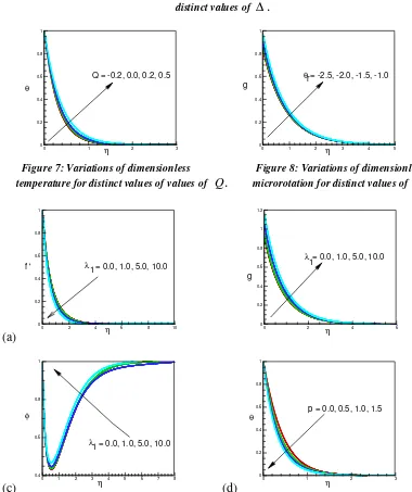
Figure 7 shows temperature profiles for different values of heat generation/absorption parameter
Q. Owing to the presence of heat generation it is apparent from this figure that there is an increase in the thermal state of the fluid as a consequence temperature profiles seem to increase. For heat absorption, opposite phenomenon is revealed.
Insignificant increase of microrotation profiles is observed in Figure 8 with an increasing value of viscosity parameter θr.
Figures 9(a)-(c) respectively show the velocity, microrotation and concentration profiles for different values of the Darcy parameter λ1. From Figure 9(a) it is observed that the velocity profiles as well as momentum boundary layer thickness decreases with the increase of λ1. The case λ =0 corresponds to a pure fluid, rather than a porous medium. The Darcy number Da the measurement of the porosity of the medium increases as the porosity of the medium increases and hence λ decreases. Fluid gets more space for large porosity of the medium to flow, as a consequence fluid velocity increases. Figure 9(b) shows the effect of λ1 on the microrotation profiles. The microrotation is found to increase as λ1 increases. From Figure 9(c) it is found that increasing λ1 increases concentration profiles but decreases concentration boundary layer growth. Figure 9(d) illustrates the influence of variable surface parameter
pon temperature profiles within the boundary layer. This figure indicates that with the increase of
(a)
0 1 2 3 4 5
0 0.2 0.4 0.6 0.8 1
η
f '
Fw = 0.5, 1.0, 1.5, 2.0
(b)
0 1 2 3 4 5 6
0 0.2 0.4 0.6 0.8 1 1.2 1.4 1.6
η
g
Fw = 0.5, 1.0, 1.5, 2.0
(c)
0 1 2 3
0 0.2 0.4 0.6 0.8 1
η θ
Fw = 0.5, 1.0, 1.5, 2.0
(d)
0 1 2 3 4 5 6
0.4 0.6 0.8 1
η φ
Fw = 0.5, 1.0, 1.5, 2.0
Figure 1: Variations of dimensionless (a) velocity (b) microrotation (c) temperature and
(d) concentration profiles for distinct values of Fw.
0 2 4 6
0 0.2 0.4 0.6 0.8 1
η
g
ξ= 1.0, 2.0, 3.0, 4.0
0 2 4 6
0.2 0.4 0.6 0.8 1
r = 0.0, 2.0, 3.0, 5.0
η φ
Figure 2: Variations of dimensionless Figure 3: Variations of dimensionless microrotation profiles for distinct concentration profiles for distinct values
(a)
0 2 4 6
0 0.2 0.4 0.6 0.8 1
η
f ' M = 0.0, 0.5, 0.8, 1.0
(b)
0 2 4 6
0 0.2 0.4 0.6 0.8 1
η
g M = 0.0, 0.5, 0.8, 1.0
Figure 4: Variations of dimensionless (a) velocity and (b) microrotation profiles
for distinct values of M .
(a)
0 2 4 6 8 10
0 0.2 0.4 0.6 0.8 1
n = 0.0, 0.2, 0.5, 0.8
η
f '
(b)
0 2 4 6 8 10
-0.2 0 0.2 0.4 0.6 0.8 1 1.2 1.4 1.6
n = 0.0, 0.2, 0.5, 0.8
η
g
(c)
0 2 4 6
0.4 0.6 0.8 1
n = 0.0, 0.2, 0.5, 0.8
η φ
(d)
0 1 2 3
0 0.2 0.4 0.6 0.8 1
h
θ
R = 1.0, 2.0, 3.0, 4.0
Figure 5: Variations of dimensionless (a) velocity (b) microrotation and (c) concentration
(a)
0 2 4 6
0 0.2 0.4 0.6 0.8 1
∆= 0.0, 0.5, 1.0, 1.5
η
f '
0 2 4 6
0 0.2 0.4 0.6 0.8 1 1.2
∆= 0.0, 0.5, 1.0, 1.5
g
η
Figure 6: Variations of dimensionless (a) velocity and (b) microrotation profiles for
distinct values of ∆ .
0 1 2 3
0 0.2 0.4 0.6 0.8 1
η θ
Q = -0.2, 0.0, 0.2, 0.5
0 1 2 3 4 5
0 0.2 0.4 0.6 0.8 1
g
η
θr= -2.5, -2.0, -1.5, -1.0
Figure 7: Variations of dimensionless Figure 8: Variations of dimensionless
temperature for distinct values of values of Q. microrotation for distinct values of θr.
(a)
0 2 4 6 8 10
0 0.2 0.4 0.6 0.8 1
λ1 = 0.0, 1.0, 5.0, 10.0
η
f '
0 2 4 6
0 0.2 0.4 0.6 0.8 1 1.2
λ
1= 0.0, 1.0, 5.0, 10.0
η
g
(c)
0 1 2 3 4 5 6 7 8
0.4 0.6 0.8 1
λ = 0.0, 1.0, 5.0, 10.0
η φ
1
(d)
0 1 2 3
0 0.2 0.4 0.6 0.8 1
p = 0.0, 0.5, 1.0, 1.5
η θ
Figure 9: Variations of dimensionless (a) velocity (b) microrotation (c) concentration profiles for distinct values of λ1
(a)
0 0.1 0.2 0.3 0.4 0.5
-1.94 -1.93 -1.92 -1.91 -1.9 -1.89 -1.88
Q
f
''
(0
)
R = 1, 2, 3, 4
(b)
0 0.1 0.2 0.3 0.4 0.5
-1.22 -1.218 -1.216 -1.214 -1.212 -1.21 -1.208 -1.206
Q
g
'(
0
)
R = 1, 2, 3, 4
(c)
0 0.1 0.2 0.3 0.4 0.5
2 2.5 3 3.5 4 4.5 5 5.5
Q
θ-'(
0
)
R = 1, 2, 3, 4
(d)
0 0.1 0.2 0.3 0.4 0.5
-5 -4 -3 -2
Q
'(
0
)
R = 1, 2, 3, 4
φ
Figure 10: Variations of Rand Q on (a) local skin-friction coefficient (b) rate of
coupling (c) surface heat transfer and (d) surface deposition flux.
(a)
0.2 0.4 0.6 0.8 1
-2.15 -2.1 -2.05 -2 -1.95 -1.9 -1.85 -1.8
λ1= 0, 1, 5
Scv
f
''
(0
)
(b)
0.2 0.4 0.6 0.8 1
-1.4 -1.3 -1.2 -1.1
Scv
g
'
(0
)
λ
1 = 0, 1, 5
(c)
0.2 0.4 0.6 0.8 1
2.55 2.6 2.65 2.7 2.75
v Sc
λ1 = 0, 1, 5
-'
(0
)
θ
(d)
0.2 0.4 0.6 0.8 1
-4.5 -4 -3.5 -3 -2.5 -2 -1.5 -1 -0.5
φ'
(0
)
= 0, 1, 5
λ
1
Scv
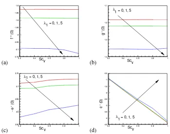
Figure 11: Variations of λ1 and Scv on (a) local skin-friction coefficient (b) rate of
0.6 0.8 1 1.2 1.4 1.6 1.8 2 -8
-7 -6 -5 -4 -3 -2 -1
r = 0, 1, 2, 3
Fw
φ'(
0
)
Figure 12: Variations of r and Fw on surface deposition flux.
Figure 10(a) shows the local skin friction coefficient for different values of R and Q. From here we see that f ′′(0) decreases as R increases. For fixed value of R, in the case of heat generation (Q〉0), f ′′(0) increases and thus to be understood, for heat absorption (Q〈0), f ′′(0)decreases. Figure 10(b) shows the rate of coupling for different values of Q and R. This figure reveals that for fixed Q, the rate of coupling increases with the increases of R. On the contrary, for fixed value of R the rate of coupling g′(0) decreases with the increase of Q. The effect of radiation on the rate of heat transfer from the surface of the sheet for different values of Q is illustrated in Figure 10(c). From here we see that for fixed R the rate of heat transfer from the heated surface decreases with the increase of the heat generation parameter Q. This is expected since the heat generation mechanism will increase the fluid temperature near the surface. On the other hand, the presence of heat absorption (Q〈0) creates a layer of cold fluid adjacent to the heated surface and therefore the heat transfer rate from the surface increases. From this figure it is also clear that the rate of heat transfer increases with the increase of Radiation parameter R. We see from Figure 10(d) that with the increase of R the surface deposition flux ϕ′(0)
decreases strongly whereas ϕ′(0) increases with an increase of heat generation Q〉0.
Figures 11(a)-(c) show that if Darcy parameter λ1 increases then the physical parameters f ′′(0),
) 0 (
g′ and −θ′(0) decrease. We observe that these physical parameters decrease very quick for higher value of λ1(=5). Again, for a fixed value of λ1 except higher like λ1(=5), the values of f ′′(0), g′(0)
and −θ′(0)remain almost uniform without varying with increase of Scv. Figure 11(d) displays that
) 0 (
ϕ′ enhances very slowly with the increase of values of λ1. But for any fixed value of λ1, with the increase of Scv, ϕ′(0)decreases strongly.The effect of thermophoretic parameter τ and suction parameter Fw on surface deposition flux φ′(0) is shown in Figure 12. In this figure we find that
) 0 (
φ′ decreases effectively with the increase of τ . It is also clear from this figure that for any fixed value of τ , φ′(0)decreases rapidly with the increase of Fw.
VI. CONCLUSIONS
transformed into non-linear ordinary equations using similarity transformations and then solved with Nachtsheim-Swigert shooting iteration technique. The following results of the numerical computations can be drawn as conclusions:
1. The velocity profiles increase with the increase of vortex viscosity parameter ∆ whereas velocity profiles decreases with increase of suction parameter Fw, magnetic field parameter M, microrotation
parameter n and Darcy parameter λ1.
2. The microrotation profiles increeases with increases of suction parameter Fw, spin-gradient viscosity
parameter ξ, magnetic field parameter M , microrotation parameter n and viscosity parameter θr whereas microrotaion profiles decreases with increase of vortex viscosity parameter ∆.
3. The temperature profiles increase with the increase of microrotation parameter n and heat generation/absorption parameter Q whereas temperature profiles decrease with the increase of suction parameter Fw, variable surface temperature parameter p and radiation parameter R.
4. The concentration boundary layer growth increases with the increase of variable concentration whereas concentration boundary layer growth decreases with the increase of suction parameter Fw,
microrotation parameter n and Darcy parameter λ1.
5. The local friction coefficient increases with the increase of heat generation Q〉0 whereas decreases with the increase of radiation parameter R.
6. The rate of coupling increases with the increase of radiation parameter Rwhereas this physical parameter decreases with the increases of heat generation Q〉0.
7. The rate of heat transfer from the surface of the sheet increases with the increases of radiation parameter Rwhereas this physical parameter decreases with the increases of heat generation Q〉0. 8. The surface deposition flux increases with the increase of heat generation Q〉0whereas this surface deposition flux decreases with the increase of radiation parameter R.
BIBLIOGRAPHY
[1] Hossain, M. A. and Takhar, H. S. 1996. Radiation effect on mixed convection along a vertical plate with uniform surface temperature, Heat Mass Transfer, 3: 1243-248.
[2] Raptis, A. 1998. Radiation and free convection flow through a porous medium, Int. Comm. Heat Mass Transfer,
25:289-295.
[3] Makinde, O. D. 2005. Free convection flow with thermal radiation and mass transfer past a moving vertical porous plate, Int. Commu. Heat Mass Transfer, 32: 1411-1419.
[4] Rahman, M. M. and Sattar, M. A. 2007. Transient convective flow of micropolar fluid past a continuously moving vertical porous plate in the presence of radiation, Int. Jour. Appl. Mechs. Engg., 12: 497-513.
[5] Ibrahim F. S. , Elaiw, A. M. and Bakr, A. A. 2008. Inuence of viscous dissipation and radiation on unsteady MHD mixed convection flow of micropolar fluids, Appl. Math. Inf. Sci., 2:143-162.
[6] Uddin, Z., Kumar, M., and Bisht, V. 2009. Radiation heat transfer effect on a moving semi-infinite tilted porous heated plate with uniform suction in the presence of transverse magnetic field, Ganita,60(1): 69-79.
[7] Ishak, A. 2010. Thermal boundary layer flow over a stretching sheet in a micropolar fluid with radiation effect,
Meccanica, 45: 367-373.
[8] Das, K. 2011. Effects of heat and mass transfer on MHD free convection flow near a moving vertical plate of a radiating and chemically reacting fluid, Jour. Siberian Federal Univ. Maths. and Phys., 4: 18-31.
[9] [9] Mukhopadhyay, S., De, P. R., Bhattacharyya, K. and Layek, G. C. 2012. Forced convection flow and heat transfer over a porous plate in a Darcy-Forchheimer porous medium in presence of radiation, Meccanica,47: 153-161.
[11] Reddy, K. S. N., Babu, M. S., Varma, S.V.K. and Reddy, N. B. 2014. Hall current and dufour effects on mhd flow of a micropolar fluid past a vertical plate in the presence of radiation absorption and chemical reaction, IOSR Journal of Mathematics,10(4): 106-121.
[12] El-Dabe, N. T., Ghaly, A. Y., Rizkallah, R. R., Ewis, K. M. and Bareda, A. S. 2015. Numerical solution of MHD flow of micropolar fluid with heat and mass transfer towards a stagnation point on a vertical plate, American Journal of Computational Mathematics, 5:58-174.
[13] Raptis, A., Tzivanidis, G. and Kafousias, N. 1981.Free convection and mass transfer flow through a porous medium bounded by an infinite vertical limiting surface with constant suction, Letters in Heat and Mass Transfer, 8(5): 417-4241.
[14] Tamayol, A., Firoozabadi, B. and Emdad, H.2006. Heat transfer in a porous medium over a stretching surface with injection or suction and with different thermal boundary conditions, Proceedings of the 3rd BSME-ASME International Conference on Thermal Engineering,20-22 December, Dhaka, Bangladesh.
[28] Pop, I. and Ingham, D. B. 2001. Convective heat transfer: mathematical and computational modeling of viscous fluids and porous media, Pergamon, Oxford.
[29] Nield, D. A. and Bejan, A. 2006. Convection in porous media, Springer, New York.
[30] Ahmed, S.2012. Mathematical model of induced magnetic field with viscous/magnetic dissipation bounded by a porous vertical plate in the presence of radiation, International journal of Mathematic and mechanics, 8 (1): 86-104.
[31] Rashad, A. M., Abbasbandy, S. and Chamkha, A. J. 2014. Mixed convection flow of a micropolar fluid over a continuously moving vertical surface immersed in a thermally and solutally stratified medium with chemical reaction,
Journal of the Taiwan Institute of Chemical Engineers45: 2163–2169.
[32] Bakr, A. A., Raizah, Z. A. S. and Elaiw, A. M. 2015. MHD micropolar fluid near a vertical plate with newtonian heating and thermal radiation in the presence of mass diffusion, Pure and Applied Mathematics Journal, 4(3): 80-89. [33] Eringen, A. C. 1966. Theory of micropolar fluids, J. Math. Mech., 16: 1–18.
[34] Peddieson, J. and McNitt, R. P.1970. Boundary layer theory for micropolar fluid, Recent Adv. Eng. Sci., 5: 405–426. [35] Gorla, R. S. R. 1983. Heat transfer in micropolar boundary layer flow over a flat plate, Int. J. Eng Sci., 21: 791–796. [36] Hady, F. M. 1996. On the heat transfer to micropolar fluid from a non-isothermal stretching sheet with injection, Int. J.
Num. Meth. Heat Fluid Flow, 6: 99–104.
[37] Kelson, N. A. and Desseaux, A. 2001. Effects of surface conditions on flow of a micropolar fluid driven by a porous stretching sheet, Int. J. Eng. Sci.,39: 1881–1897.
[38] Abo-Eldahab, E. M. and Aziz, M. A. E. 2005. Flow and heat transfer in a micropolar fluid past a stretching surface embedded in a non-Darcian porous medium with uniform free stream, Appl. Math. Comput., 162: 881–899.
[39] Aouadi, M. 2007. Numerical study for micropolar flow over a stretching sheet, Comp. Mater. Sci., 38: 774–780. [40] Modather, M., Rashad, A. M. and El-Kabeir, S. M. M. 2012. Influences of temperature dependent viscosity and thermal
conductivity on the unsteady flow and heat transfer of a micropolar fluid over a stretching sheet, Latin American Applied Research, 42:121-126.
[41] Reddy, M. G.2013. Heat generation and radiation effects on steady MHD free convection flow of micropolar fluid past a moving surface, Journal of Computational and Applied Research in Mechanical Engineering, 2(2): 1-10.
[42] Mutlag, A. A., Uddin, M. J. and Ismail, A. I. M. 2014. Scaling transformation for free convection flow of a micropolar fluid along a moving vertical plate in a porous medium with velocity and thermal slip boundary conditions, Sains Malaysiana, 43(8): 1249–1257.
[43] Alam, M. S., Islam, T, and Rahman, M. M. 2015. Unsteady hydromagnetic forced convective heat transfer flow of a micropolar fluid along a porous wedge with convective surface boundary condition, International Journal of Heat and Technology, 33(2).
[44] Sakiadis, B. C. 1961. Boundary layer behavior on continuous solid surface: II the boundary layer on a continuous flat surface, AIChE J., 7(1): 221-225.
[45] Erickson, L. E., Fan, L. T. and Fox, V. G.1966. Heat and mass transfer on a moving continuous flat plate with suction and injection, Ind. Eng. Chem. Fundam., 5: 9-25.
[46] Tsou, F. K., Sparrow, E. M. and Goldstein, R. J. 1967. Flow and heat transfer in the boundary layer in continuous moving surface. Int. J. Heat Mass Transfer, 10: 219-235.
[47] Crane, L.J. 1970. Flow past a stretching plane, ZAMP, 21: 645-647.
[48] Gupta, P.S. and Gupta, A. S. 1977. Heat and mass transfer with suction and blowing, Can. J. Chem. Eng., 55: 744-746, 1977.
[49] Chen, C. K. and Char, M. 1980. Heat transfer of a continuous stretching surface with suction or blowing, J. Math. Anal. Appl., 135: 568-580.
[51] Ishak, A., Nazar, R. and Pop, I. 2008. Hydromagnetic flow and heat transfer adjacent to a stretching sheet, Heat Mass Transfer, 44: 921-927.
[52] Reddy, M. G. 2012. Heat generation and thermal radiation effects over a stretching sheet in a micropolar fluid, ISRN Thermodynamics, 1- 6.
[53] Saha, K., Salah Uddin, L. K. M. and Taher, M. A. 2015. Effect of internal heat generation or absorption on MHD mixed convection flow in a fluid driven cavity, American Journal of Applied Mathematics, 3(1-1): 20-29.
[54] Rahman, M. M. and Sultana, T. 2008. Radiative heat transfer flow of micropolar fluid with variable heat flux in a porous medium, Nonlinear Analysis: Modelling and Control, 13(1): 71-87.
[55] Alam, S., Rahman, M. M., Maleque, A. and Ferdows, M. 2006. Dufour and Soret effects on steady MHD combined free-forced convective and mass transfer flow past a semi-infinite vertical plate, Thammasat Int. J. Sc. Tech., 11(2): 1-12.
[56] Nachtsheim, P.R. and Swigert, P. 1965. Satisfaction of the asymptotic boundary conditions in numerical solution of the system of non-linear equations of boundary layer type, NASSA TND-3004.
![Table-1: Comparision of the present results with those of Abdou et al. [44]](https://thumb-us.123doks.com/thumbv2/123dok_us/9842158.1970607/7.595.92.522.255.385/table-comparision-present-results-abdou-et-al.webp)