IMPACT SPRINKLER PATTERN MODIFICATION
D. C. Kincaid MEMBER
ASAE
ABSTRACT
Methods of modifying the water distribution pattern of an impact-drive sprinkler are described. A method of pattern modification called intermittent diffusion is introduced. A deflector attached to the drive arm intermittently diffuses the jet of a standard circular-orifice nozzle, producing desirable pattern shapes while maintaining a large pattern radius. Uniformity of application for both wind and no-wind conditions was evaluated using both the deflector and diffuse type nozzles. The deflector is beneficial for low pressure sprinkling, particularly under windy conditions. Equations were developed to predict the operating characteristics of the impact arm. KEYWORDS. Sprinklers, Sprinkler irrigation, Distribution.
INTRODUCTION
S
tationary type sprinkler irrigation systems (hand move, solid set, and sideroll laterals) are used on approximately 8 million acres of agricultural land in the U. S. (Irrigation Journal, 1990). The impact-type sprinkler is used predominately on these systems because of its low cost and reliability. Its basic design has changed very little since it was introduced 50 years ago. The water application patterns of these sprinklers can be varied by adjusting nozzle pressure or by using fixed deflectors, multiple nozzles, or diffuse nozzles. As energy costs increase, there is a need to find ways to operate sprinkler systems at reduced pressures without reducing spacings, while maintaining high uniformity of application.
The main objective of this article is to introduce and evaluate a new method of pattern modification using the impact arm, and compare this method with previous methods. A secondary objective was to develop equations describing the mechanics of the impact arm, which may prove useful in optimizing the deflector-drive impact arm.
PATTERN MODIFICATION METHODS
The ordinary round or straight-bore nozzle produces a relatively undisturbed jet and produces the largest pattern radius for a given pressure and flow rate (Kincaid, 1982).
Article was submitted for publication in April 1991: reviewed and approved for publication by the Soil and Water Div. of ASAE in October
1991.
Trade names and company names are included for the benefit of the reader and do not imply any endorsement or preferential treatment of the product listed by the USDA-Agricultural Research Service.
The author is Dennis C. Kincaid, Agricultural Engineer. USDA-Agricultural Research Service. Kimberly, ID.
Use of a straightening vane upstream of the nozzle minimizes diffusion of the jet and helps to maximize the pattern radius. With high pressures, the jet breaks up sufficiently to produce a desirable pattern shape. However, as pressure is reduced, the pattern becomes annular or doughnut shaped. It then becomes necessary to mechanically break up or diffuse the jet to produce a desirable pattern. Desirable application patterns can vary from the classical triangular (application rate decreases linearly with distance from the sprinkler) to a rectangular (constant rate) shape, but should have continuously decreasing application rates with distance from the sprinkler.
One method of diffusing the jet is to use a fixed deflector on top of the jet or a pin protruding into the jet. These devices are usually mounted beyond the impact arm, and are mainly used to reduce the pattern radius where necessary. Recently, manufacturers have developed noncircular orifice nozzles which produce diffuse jets and improved patterns with low pressures. The disadvantage of the diffuse-jet type of nozzle is that the jet has a large cross-section which is easily deflected by wind, and the pattern radius is reduced. Also, the diffuse jet does not operate the impact arm as efficiently as a smooth jet, resulting in possible rotation problems.
A secondary nozzle can be used to fill in portions of the pattern. Multiple-nozzle sprinklers have not been popular for low application rates because, for a given flow, they require smaller nozzles, which reduces the potential pattern radius and may cause plugging problems.
Flow control nozzles have recently been developed that use a circular orifice which contracts as pressure increases. These nozzles maintain flow within about 5% of nominal flow over a wide pressure range. They produce patterns very similar to those of the circular fixed-orifice nozzles.
The ideal sprinkler for large field applications would be one which uses circular orifice, fixed or flow-control nozzles to maximize pattern radius for a given pressure and flow rate, while avoiding the doughnut (annular) shaped patterns characteristic of circular nozzles. This can be done by intermittently deflecting the jet to fill in the intermediate portion of the pattern. Intermittent diffusion can be accomplished by attaching a deflector to the impact arm. Several types of deflectors were tested before settling on the configuration shown in figures 1 and 2.
IMPACT DRIVE MECHANICS
0 .
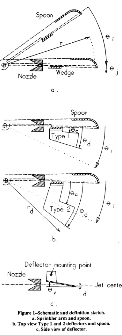
Figure la shows a schematic of the spoon, nozzle, and the deflector and its mounting point. Figure lb shows a schematic of the deflector design which is divided into two types which will be discussed later. Figure 2 shows the deflector parts, including a spacer and mounting screw, and the deflector mounted on a sprinkler. A hole is drilled in the arm and threaded to accept the mounting screw. The deflector shown is 40 mm in length and was cut from 2 mm thick aluminum angle.
The basic relationship describing the movement of the impact arm is:
a = dco/dt = (d MO) (dO/dt):z do.) /d0 = / ( I)
where
CC = is angular acceleration of the arm (rad/s 2 ),
= is angular velocity (rad/s),
T = is spring torque acting on the arm at any
instant (N-m),
I = is moment of inertia of the arm (kg-m 2 ), = is angle of rotation (rad), measured clockwise
from the position of maximum extension (see fig. 1) when 0.) = 0, t = 0, and t is time (s).
In this analysis, the angle 0 = 0 and time t = 0 when the arm is fully extended and beginning to rotate toward the sprinkler body. The arm accelerates until it strikes the sprinkler body at some angle 0 i , called the impact angle. The spoon wedge interrupts the jet a few degrees before impact, however, for the present the effect of the wedge on the arm acceleration will be ignored. The spring torque on the arm is given by:
T = To +CO.—CO= Tm — C 0 (2)
Deflector mounting point
Nozzle
_ _ _ _•_ _•_ _ _ L - - Jet center
e
vd
c.
Figure 1—Schematic and definition sketch. a. Sprinkler arm and spoon. b. Top view Type 1 and 2 deflectors and spoon.
c. Side view of deflector.
a spoon which momentarily deflects the water jet horizontally, providing an impulse which imparts angular momentum to the arm. The spring gradually absorbs this momentum and returns the arm to impact the body and rotate the sprinkler slightly. The design of the arm and spoon has been optimized to rotate the sprinkler at a slow rate while minimizing the amount of water deflected by the spoon. The spoon-deflected water generally falls close to the sprinkler.
The following relationships were developed to aid in understanding how an arm-mounted deflector could be designed to deflect the jet for a desired percentage of time, and thus produce a desired pattern shape.
where C is the spring constant (N-m/rad), To is torque
(N-m) when 0 = 0 1 , and Tm is the maximum torque (N-m)
at 0 = 0.
Combining equations 1 and 2, and integrating, results in an equation giving velocity as a function of angle:
4 .5 = ((C /I) (200 0– 0
where 0 0 = to/C + 0; and T = 0 at 0 = Op. The
manufacturers pre-loaded spring torque is To.
By substituting dO/dt for co in equation 3 and integrating, we obtain an equation for time as a function of angle:
t = 2 (I /C)" sin- 1 [0/(20o) r 5 ] (4)
Using equation 4, and letting ti be the time when 0 = 0 i , results in the following dimensionless equation:
a. b. C.
Figure 2—Sprinkler and deflector.
a. Sprinkler with mounting hole drilled in arm, spacer, deflector, and mounting screw. b. Top view of mounted deflector.
c. Side view.
t /t, = sin- I [(p0/(20,) )0.5 ] /sin - 1[(p/2)°.5] (5)
where p = 0;/0 0.
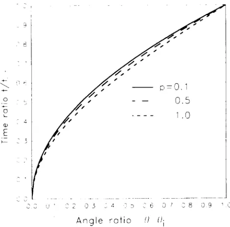
Equation 5 is plotted in figure 3 for values of p from 0.1 to 1.0. Figure 3 shows that the dimensionless angle-time relationship is very insensitive to p. The percent of time that the jet is undisturbed by the spoon is not very sensitive to initial spring torque. For example, if it is desired to deflect the jet for 30% of the time that the jet is undisturbed by the spoon, the deflector angle should cover about 45 to
Angle ratio () /II
Figure 3—Rotation angle-time relationship for a spring operated impact arm, p i /9 0 .
50% of the normally undisturbed angle (0.50 < 0/0; < 0.55) (refer to fig. 3). Figure 1 shows the deflector angle Od.
The angular velocity of the arm at impact (0 = 0;) can be determined from equation 3. The velocity and angle 0; is also determined by the impulse of the jet acting on the spoon. Referring to figure la, it is assumed that the spoon deflects the jet at a right angle at a radius, r. The torque created by the jet acting on the spoon is:
..r.
1=pqVr (6)
where Ti = torque (N-m),
V = jet velocity (m/s), r = impulse radius (m), q = nozzle flow rate (L/s), and P = density of water 1 kg/L.
The acceleration due to the jet impulse is:
a =(ti– to)/I (7)
Combining equation 7 with the equality code) = lade (from eq. 1), and integrating yields (assuming that the torque is constant for the small impulse angle):
2
o) /2 = Opj — To)/i
where 9i is the jet impulse angle (rad).
Equation 8 can be combined with equation 3 with 0 = 0; and CO eliminated to obtain:
0.5
a =(02 p + 2 2 ) – 0j p
(8)
where Op = to/C is the preload angle and 02 = - TO/C.
Note that the arm impact angle, 01, is independent of the moment of inertia and is dependent only upon the spring constant and preload angle, and somewhat dependent on nozzle flow due to the effect of equation 6 on equation 9.
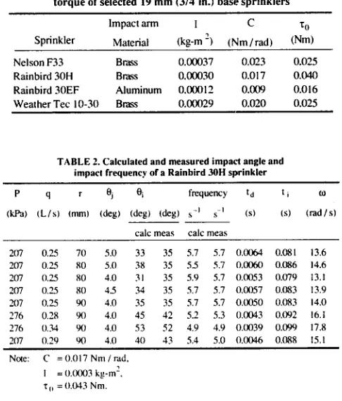
Table 1 gives measured moment of inertia, spring constant, and initial torque from several sprinklers. The moment of inertia was measured by alternately weighing the arm, cutting off segments of the arm in 10 mm radial increments and calculating the inertia of each segment. The spring constant was calculated from spring torque measurements at angles of 0 and 45° (measured counterclockwise from the sprinkler body). Note that the aluminum arm has much lower moment of inertia and spring constant. However, the ratio I/C is relatively constant, resulting in nearly equal impact frequencies for these sprinklers.
Data for verification of equations 4 through 9 were obtained by using a video camera mounted directly above an operating sprinkler to measure the impact angle and impact frequency (number of impacts per second). The camera recorded 60 frames per second, and by using single frame advance the angle was determined within about 2° accuracy. The impact frequency was accurately determined by counting frames through several cycles.
Table 2 lists the measured parameters and compares calculated and measured impact angle and frequency for a sprinkler using straight bore nozzles and two pressures. The first four columns and the note at the end of the table give measured input parameters, and the rest are calculated. The procedure is to first calculate the impact angle using equation 9, and then calculate the time ti using equation 4. The impact frequency is 1/(2(ti + td)), where td is the time required to accelerate the arm, and td = 0j/co, where co is calculated by equation 8. The flow was measured and nozzle jet velocity was determined as V = 1.416 P0•5, where P is pressure in kPa.
The angle 0i is the most difficult parameter to measure, and was initially estimated at 5°. The first five lines of Table 2 show the sensitivity of the calculated impact angle and frequency to the values Oi and r. The calculated angle 01 changed roughly in proportion to a change in r or 0i. However, the frequency changed only about 1/3 as much as 01. It appears that good results can be obtained by setting r equal to the distance to the spoon (90 mm in this case) (which assumes that the water is deflected 90° by the spoon), and then adjusting Oi until the calculated frequency agrees with the measured frequency. The last three lines in Table 2 show that the equations predicted the changes in frequency and angle reasonably well as the flow and nozzle pressure changed. The values of td, ti, and co are given for reference.
INTERMITTENT DEFLECTOR DESIGN FOR OPTIMUM PAIIERN
This section describes the development of a deflector which can be attached to the impact arm to modify the pattern of a round jet nozzle. The purpose of the deflector is to intermittently diffuse the jet so as to fill in the
TABLE 1. Moment of inertia, spring constant and initial torque of selected 19 mm (3/4 in.) base sprinklers
Impact arm C To
Sprinkler Material (kg-m 2 ) (Nm/rad) (Nm)
Nelson F33 Brass 0.00037 0.023 0.025
Rainbird 301-1 Brass 0.00030 0.017 0.040
Rainbird 30EF Aluminum 0.00012 0.009 0.016 Weather Tec 10-30 Brass 0.00029 0.020 0.025
TABLE 2. Calculated and measured impact angle and impact frequency of a Rainbird 30H sprinkler
(kPa) (1../s) r
(mm) (deg) (deg) (deg)
frequency t d
(s) (s) (rad / s)
calc meas calc meas
207 0.25 70 5.0 33 35 5.7 5.7 0.0064 0.081 13.6 207 0.25 80 5.0 38 35 55 5.7 0.0060 0.086 14.6 207 0.25 80 4.0 31 35 5.9 5.7 0.0053 0.079 13.1 207 0.25 80 45 34 35 5.7 5.7 0.0057 0.083 13.9 207 0.25 90 4.0 35 35 5.7 5.7 0.0050 0.083 14.0 276 0.28 90 4.0 45 42 5.2 5.3 0.0043 0.092 16.1 276 0.34 90 4.0 53 52 4.9 4.9 0.0039 0.099 17.8 207 0.29 90 4.0 40 43 5.4 5.0 0.0046 0.088 15.1
Note: C = 0.017 Nm / rad,
1 = 0.0003 4.-m 2 ,
To = 0.043 Nm.
intermediate portion of the application pattern while leaving the jet undisturbed for a sufficient percentage of time to maintain a near maximum pattern radius. While diffusing the jet, the deflector must not seriously affect the operation of the arm and thus reduce the rotation rate of the sprinkler head.
The device consists of a flat plate attached to the arm above the jet but close to the nozzle. The deflector is angled so that the jet is deflected downward about 10°. The outer edge has a radius, rd, (about 75 mm in this case) and is horizontal, to minimize lateral reaction forces on the arm as the deflector passes through the jet (see fig. lc). The vertical angle, 0,„ can be adjusted so that the deflector edge passes partially or completely through the jet. This type of deflector produces a horizontally diffuse jet with a trajectory angle of about 15° (the normal jet trajectory angle is 23° to 25°).
The most important parameters are the horizontal angles 0c and Od , which are the starting and ending deflection
angles and which determine the percentage of time that the jet is deflected. The deflector denoted Type 1 is defined by
Oc < Od < Oi (see fig. lb), whereas Type 2 is defined by
< Oi < Od . In Type 1, 0c is set small (< 10°) and
Od determines the deflection time. In Type 2, Oc determines the nondeflected arc.
Flow rate: 0.31 L/s (5gpm) Pressure: 207 kPa (30 psi)
Nozzle
— CD 1 1 /64 - - MG9S --- FCN 5.0
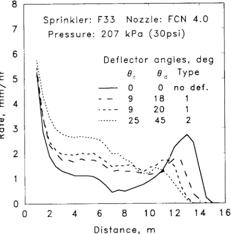
Sprinkler: F33 Nozzle: FCN 4.0
Pressure: 207 kPa (30psi)
Deflector angles, deg
BC Od Type
0 0 no def.
- - 9 18 1
---- 9 20 1
25 45 2
N...s • — —
Sprinkler: F33 Nozzle: FCN 4
2 4 6 8
Distance, m _c
E E
ai a
vary between 1 to 4 mm without changing the pattern significantly.
The deflector was developed and tested by running indoor radial-leg (single collector line) pattern tests with different deflector configurations, simulating field uniformities with no wind, and comparing results with tests of both round-jet and diffuse-type nozzles. When a near optimum configuration was obtained, outdoor tests were run for a range of wind speeds and results were compared with outdoor tests of round-jet and diffuse-jet nozzles.
Indoor radial-leg tests were conducted to compare water distribution patterns with no wind, following the ASAE Standard S398.1, with a collector spacing of 0.5 m and nozzle height of 0.6 m above the collectors.
Figure 4 compares the FCN nozzle with diffuse type nozzles at nearly equal pressure and flow. The Rainbird CD nozzle uses a square orifice, and the MG9S is a triangular orifice nozzle. The diffuse nozzles convert annular shaped patterns to nearly horizontal or rectangular patterns with a reduced radius. The arm spoon spray produces a high rate near the sprinkler which is increased by the diffuse jet.
Figure 5 compares patterns from a nozzle with the two types of deflectors with the pattern from the same nozzle without a deflector. The deflector radius, rd, was 75 mm, the vertical angle, 0,,„ was 10° and the deflector distance, d, was 1 mm. The Type 2 deflector produced a nearly triangular pattern but reduced the pattern radius more than Type 1.
The equations and figure 3 can be used to estimate the percentage of time that the jet is deflected. For the case shown in figure 5 for the Type 1, 9-20 deflector, and using parameters from Table 1 for the F33 sprinkler, the impact angle was calculated at 45°, 00 = 107°, and p = 0.4. The undeflected arc is (45-20) = 25° and the ratio 0/8; = 25/45 = 0.56. From figure 3, t/ti = 0.73, which is the fraction of time undeflected. The jet is therefore deflected 27% of the time.
2 4 6 8 10 12 14 16
Distance,
Figure 4-Comparison of patterns with different nozzle types.
2 4 6 8 10 12 14 16
Distance, m
Figure 5-Effect of intermittent deflector on rate pattern.
The impact angle increases with pressure or flow rate as shown in Table 2. With a Type 1 deflector, as the pressure increases, the impact angle increases and thus the percentage of time that the jet is deflected decreases. The Type 1 deflector is thus easier to design for a range of pressures and flow rates. Figure 6 shows the effect of nozzle pressure on the Type 1 deflector pattern. To insure adequate duration of deflection, the deflector should be designed for the lowest operating pressure.
Figure 6-Effect of pressure on pattern with a Type 1 deflector, 0c = 9, = 18°.
_c 5
E E 4
-a>
3
Sprinkler: F33 Nozzle: FCN 4
Spacing: 1 2x 1 5m Pressure kPa(psi) 207(30)D 276(40)D 345(50)D 207(30)N 276(40)N 345(50)N
50
0 1 2 3 4 5 6 7 8
Windspeed, m/s
Figure 8-Uniformity vs. windspeed with FCN 5 nozzle at three pressures, with (D) and without (N) the Type 1 deflector.
100
E
0 C
95 Spacing: 12x15m
90
85
80
75
70
65
60
55
Sprinkler: F33 Nozzle: FCN 5
Pressure kPa(psi) 207(30)D - - 276(40)D -- 345(50)D 207(30)N 276(40)N 345(50)N 100
95
90
85
80
75
70
65
60
55
50 0
TABLE 3. Uniformity coefficient (CU%) for various nozzle deflector combinations, with square spacings and no wind, using a Nelson F33 sprinkler
Nozzle Pressure 1cPa (psi)
Deft deg
Radius Spacing m (ft)
m 12 (40) 14 (45) 15 (50) 17155) 18 (60;
Triangular. 15 97 95 97 96 89
Rectangular' 15 88 87 80 73 80
FCN4t 207 30 25-32 13 88 90 90 87 84 FCN4t 276 40 25-32 14 90 90 88 86 84 FCN4t 207 30 9-20 13 85 81 81 82 77 FCN4t 207 30 9-18 14 86 82 78 78 80 FCN4t 207 40 9-18 15 85 85 81 79 80 FCN 4t 207 30 none 145 69 75 61 55 60 FCN4t 276 40 none 155 71 81 73 65 66 FCN4t 345 50 none 16 77 86 78 71 70 FCN4t 414 60 none 16 81 87 79 75 75 FCN 5 207 30 none 15 73 77 64 61 65 FCN 6 207 30 none 15 78 79 66 63 67 FCN 6 276 40 none 16 78 85 76 70 73 FCN 6 345 50 none 16 80 88 80 74 74 FCN 6 414 60 none 16 84 90 81 77 77 MG 8S'. 241 35 none 135 83 79 78 81 77 MG 9St 207 30 none 13 81 79 80 80 74 RND 5 / 32§ 207 30 none 135 81 66 63 70 60 CD 11 / 6411 207 30 none 14 89 83 80 84 79 • Indicates simulated distribution patterns.
t Nelson Flow Control Nozzle. 4 gpm nominal flow. Triangular orifice nozzles.
§ Straight bore nozzle, size in inches. 1 Square orifice nozzle.
WATER APPLICATION UNIFORMITY
Table 3 lists computed Christiansen (1942) uniformity coefficients (%) for 12 to 18 m square sprinkler spacings using data obtained from the indoor tests. Average application rate ranges from 3 to 9 mm/h for these simulations. The first two lines represent hypothetical triangular and rectangular distribution patterns for comparison. The next five lines are for deflected patterns as shown in figure 5, where 9-18 and 9-20° represents Type 1, and 25-45° is the Type 2 deflector.
The triangular distribution pattern gives high uniformity for all spacings, as expected, and the rectangular distribution pattern gives CU values above 80% with spacings smaller than the pattern radius. The circular FCN nozzles require high pressure to achieve high uniformity (> 80%). However, with the deflectors, these nozzles achieved high CU at much lower pressures. The Type 2 deflector gave higher CU than the Type 1, indicating that for no-wind conditions, achieving a nearly triangular pattern is more advantageous than a large pattern radius. The Type 2 deflector gave better CU values than the diffuse type nozzles.
Outdoor single-sprinkler pattern tests were run using the Type 1 and Type 2 deflectors to determine how well they would perform under windy conditions in comparison with other types of nozzle configurations. The tests were conducted according to ASAE Standard S330.1. The collector spacing was 2 m, and the nozzle height was 0.6 m. Tests were run for 1 to 2 hours when the windspeed and direction were nearly constant. A computer program was used to calculate uniformity for different spacing combinations and wind directions. A 12 by 15 m spacing was chosen for comparison, and the uniformity data are averaged for four different wind directions.
Figures 7 and 8 show the effect of windspeed on uniformity using 0.25 L/s (4 gpm) and 0.32 L/s (5 gpm)
Windspeed, mi/hr
0 2 4 6 8 10 12 14 16
1 ' 2 3 4 5 6 7 8
Windspeed, m/s
Figure 7-Uniformity vs. windspeed with FCN 4 nozzle at 3 pressures, with (D) and without (N) the Type 1 deflector.
Flow Control nozzles, respectively, at three different nozzle pressures, with and without the Type 1 deflector. The deflector significantly improved uniformity at windspeeds below 5 m/s but the data is inconclusive for higher windspeeds.
Figure 9 compares the Type 1 and 2 deflectors. It appears that although the Type 2 deflector produced better uniformity with no wind, the Type 1 deflector performs better under wind conditions. This is probably due to the fact that Type 1 deflects the jet only once each arm cycle,
Windspeed, mi/hr
Sprinkler: F33 Nozzle: FCN 4
Spacing: 12x15m Pressure 207 kPa
Deflector Type 1 Type 2 - — None
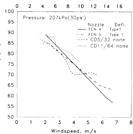
Pressure: 207kPa(30pti)
Nozzle Defl. FCN 4 Typel - — FCN 5 Type 1
- - CD5/32 none CD11/64 none
Windspeed, mi/hr Windspeed, mi/hr
0 2 4 6 8 10 12 14 16 0 2 4 6 8 10 12 14 16
100 95
90
85 80 75
70
65 60
55 50
0 1 2 3 4 5 6 7
Windspeed, m/s
Figure 9—Uniformity vs. windspeed with two types of deflectors.
100
95
90
85
80
75
70
65
60
55
8 2 3 4 5 6
Windspeed, m/s
Figure 10—Uniformity vs. windspeed comparing the Type 1 deflector
with square (CD) nozzles.
50
0 1 7
leaving the jet undisturbed for longer periods, which helps to maintain a larger pattern radius, as shown in figure 5.
Figure 10 compares the deflector tests with the diffuse jet CD nozzle. The deflector appears to perform as well or better than the diffuse jet at medium and low windspeeds, but may not perform better at high winds (> 5 m/s).
DISCUSSION AND CONCLUSION
The intermittent deflector was conceived as a means of modifying the application pattern of a sprinkler without using continuous jet diffusion techniques. The tests with no wind show that by adjusting the angles of the deflector, the distribution pattern can be made to approach the triangular shape with a slight reduction in pattern radius, which results in high uniformities of application. However, the outdoor tests show that the classical triangular distribution pattern is not necessarily optimum, a more rectangular pattern with a larger radius being more advantageous for windy conditions.
The Type 2 deflector gave the best results with no wind. It appears that the Type 1 deflector, in which the jet is undeflected once per impact arm cycle, and the jet is deflected approximately 30% of the time, is the best configuration for wind conditions. It is also smaller and
easier to build than Type 2. This type deflector is easily adjusted and maintains relatively high uniformity for a reasonably wide range of nozzle pressures and flows. A high degree of uniformity and flow control, over a wide pressure range, can be obtained with flow control nozzles and the intermittent deflector.
The addition of the deflector creates a slight imbalance in the arm which can cause increased vibration of the sprinkler if the riser is flexible. If this is a problem, the arm may need to be rebalanced with the deflector in place.
REFERENCES
ASAE Standards, 36th Ed. 1989. S330.I. Procedure for sprinkler distribution testing for research purposes. St. Joseph, MI: ASAE.
ASAE Standards, 36th Ed. 1989. 5398.1. Procedure for sprinkler testing and performance reporting. St. Joseph, MI: ASAE.
Christiansen, J. E. 1942. Irrigation by Sprinkling. California Eg. Exp. Sta. Bulletin 570.
Irrigation Journal. 1990. 1989 Irrigation Survey. Irrigation Journal 40(1):23-34.