DOI:10.5545/sv-jme.2017.4332 Original Scientific Paper Accepted for publication: 2017-04-24
0 INTRODUCTION
A transverse crack occurs due to fatigue, creep or both in the rotating machinery during operation, To prevent a serious accident caused by a cracked rotor, it is very important to discover the crack at the early stage of the crack propagation. Therefore, various kinds of diagnosis system have been developed to detect a crack in the rotating machinery. Verney and Green presented an on-line crack diagnosis regimen hinging on the accuracy of the crack model which should account for the crack’s depth and location
[1]. Silani et al. introduced a new finite element (FE) approach to detect small cracks and calculated the flexibility matrix of crack elements with modified
integration limits [2]. Li and Chu developed an
HHT signal processing technique on the AE feature extraction of natural fatigue cracks in rotating shafts
[3]. Guang and Chen introduced a FE model for the
crack identification of a static rotor with an open crack [4]. Ma et al. also used a FE model to calculate time-varying mesh stiffness for the effects of profile
shift and tooth crack in a gear rotor system [5].
Darpe presented a novel method of the transient torsion excitation to detect fatigue transverse cracks in rotating shafts [6]. Xie et al. studied the motion
stability of the flexible rotor-bearing system under the unsteady oil-film force and other faults by calculating
the maximum Lyapunov exponent of the system [7].
Zhu et al. [8] and Ishida and Inoue [9] theoretically and experimentally analysed the dynamic characteristics of a cracked rotor with an active magnetic bearing. Ferjaoui et al. investigated the effect of the presence of a transverse crack in a rotor supported by two
hydrodynamic journal bearings [10]. In general, the
detection methods of a crack are classified into two
groups. One, such as [4], is the static examination
where a rotating machine is dissolved, and the parts are examined independently. The other is the dynamic examination in which the changes of the vibration characteristics could be observed during the operation.
Aiming at a practical generator rotor, Chu and Wang reported that the magnitude of the harmonic resonance at the main critical speed increased and a super-harmonic resonance at the secondary critical
speed occurred due to a crack [11]. Concerning other
kinds of resonances, there is no report on practical
rotors. However, Ishida et al. [12] and Ishida and
Hirokawa [13] observed a sub-harmonic oscillation
of order 1/2, a super sub-harmonic oscillation of order 3/2 and a summing-and-differential harmonic oscillation owning to a crack in the experimental
A Practical Method to Detect a Transverse Cracked Rotor
Using Transient Response
Wang, X. – Liu, J. – Ge, W.
Xiaofeng Wang – Jun Liu* – Weimin Ge
Tianjin University of Technology, Tianjin Key Laboratory of the Design and Intelligent Control of the Advanced Mechanical System, China
To detect a transverse crack caused by fatigue or creep, most of the research has thus far paid attention only to resonances of steady-state oscillations created by the crack and proposed diagnosis systems utilizing these vibration phenomena. However, from a practical view point, these diagnosis systems have the following flaws: (1) the probability that a resonance occurs due to a crack in the rated rotational speed range is a lower position; (2) It is very dangerous to observe vibration characteristics in resonance ranges. In order to solve these problems, this paper uses a practical detection method utilizing the characteristic changes in a transient oscillation during the start-up, the shutdown, or the variable running speeds of rotating machinery. This method has great advantages, because it can check the occurrence signals of a crack in a wide speed range using a single sweep and avoid the operation in dangerous resonance ranges. Non-stationary characteristics during passages through the main resonance and various kinds of resonances are studied numerically and experimentally.
Keywords: transient response, nonlinear rotor, cracked rotor, crack identification, experiments
Highlights
• A practical method for the diagnosis of the cracked rotor has been investigated theoretically and verified systematically in many experiments.
• The characteristics of the transient response have been shown on the cracked rotor, and there is not only the harmonic resonance, but also the sub-harmonic resonance and the super harmonic resonance are analysed under the transient state. • A sensitive and accurate experimental setup has been developed with a high-quality data acquisition system to obtain precise
measurement data.
setup. Guo et al. examined the identification of the early crack propagation with the empirical mode
deposition (EMD) method [14]. Gomez et al. analysed
the vibration signals based on energy utilizing the wavelet theory. The results demonstrated the good reliability of crack diagnosis with the 3× energy [15]. Ishida et al. investigated transient responses at the 1/2
order sub-harmonic oscillation [16]. Li and Zhang
used the Hilbert-Huang Transform (HHT) to identify a crack in a rotor-bearing system under transient
oscillations [17] and [18]. Wang etc. proposed the
application of order tracking to investigate a crack
when the rotor system has a varying speed [19].
Therefore, there is a possibility that those oscillations also occur in practical machines under stationary responses or transient responses.
Although the static method is more reliable, it requires much time and money. Therefore, the dynamic examination is preferable for the early detection of a crack. Most of the dynamic monitoring systems focus on the changes of vibration characteristics in the steady-state oscillation. They have the following defects from the perspective of practice: (1) Many symptoms due to a crack do not occur in the rotational speed range; therefore, it is impossible to detect them during the normal operation; (2) When some changes occur due to a crack, it is dangerous to investigate the characteristics of the resonance range because there is a possibility that the crack develops rapidly during the investigation.
This study focuses on a practical detection method using non-stationary vibrations to overcome those defects. When a rotating machine starts up or shuts down, the rotor sweeps all over the rotational speed range below the rated rotational speed. If these non-stationary data are used to detect a crack, defects (1) and (2) could be avoided. In addition, there are some studies to illustrate systematically the transient response with simulations.
In this paper, a typical open-close model is used to investigate the characteristics of non-stationary oscillations of a cracked rotor during the passages through the main critical speed and various kinds of subcritical speeds. In particular, the study focused attention on the influences of an angular acceleration and the magnitude and phase of an unbalance on the maximum amplitude. The effectiveness of this method is verified systematically through simulations and many experiments.
To solve the above problems, the next section proposes the theoretical modelling and the motion equations. The resonances of steady-state oscillations with a crack are investigated in Section 2. The
method to detect a crack using the change of the characteristics of non-stationary oscillations passing through the harmonic resonance is explained in Sections 3 and 4. Non-stationary oscillation during passages through a forward super-harmonic and a forward sub-harmonic resonance are interpreted in Section 5. The characteristics of non-stationary oscillations during passages through a variety of resonances are summarized and shown in Section 6. The experimental setup is explained in Section 7, and the experiment results are presented in Section 8. Finally, the concluding discussion is given in Section 9.
1 THEORETICAL MODELLING AND MOTION EQUATIONS
1.1 Theoretical Modelling and Spring Characteristics
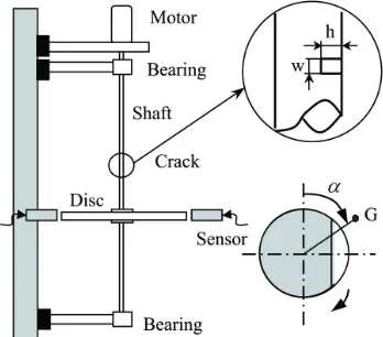
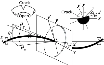
The theoretical model and the coordinate systems are shown in Fig. 1. In the experimental setup mentioned in Section 7, the rotor system where the deflection and the inclination couple each other is a four-degree-of-freedom (4DOF). The disk is not located at the shaft centre. On the contrary, if the disk is located at the shaft centre, it can be divided into two separate 2DOF systems, that is, a deflection model (the Jeffcott rotor) and an inclination model. In the latter system, the natural frequencies change due to the gyroscopic
moment similar to the 4DOF model [20]. Therefore,
we use the inclination model in the theoretical analysis. The origin of the static Cartesian coordinate
system O-xyz is at the midpoint of the bearing
centreline (the connecting line of the right and left
bearings). The z-axis coincides with the breath ring
centreline. The inclination angle of the elastic shaft at
the disk mounting position can be expressed by θ and
its projection angles of θ to the xz- and yz-planes can be expressed by θx and θy , respectively. It is supposed
that a crack appeared on the half of the shaft’s length.
The rotating coordinate system O-x'y'z' is also
considered where the x'-axis coincides with the crack boundary. The projection angles of θ to x'z- and y'z -planes can be represented by θ′x and θ′y, respectively. When the crack is opened and θ′y> 0, the stiffness of the shaft becomes small. When the crack is closed and
′
− ′ = ′ ′
− ′ = ′ − ′ ′ ′ >
− ′ = ′ + ′ ′ ′
M M M
x x
y y y
y y y
δ θ δ δ θ θ δ δ θ θ 1 2 2 2 2 0 ( ) ( ) ( ) ( ∆ ∆ << 0)
, (1)
where, δ1′ and δ2′ are the spring constants and Δδ2′ is the directional difference.
x y z ′ x ′ y τ Crack α ψ θ
θ
yθ
x o Crack (Open)ψ
′ x x y ′ yFig. 1. Model of a cracked rotor and coordinate systems
Fig. 2. Spring characteristics of a cracked rotor
1.2 Motion Equations
The ratio of the polar inertia moment to the diametric inertia moment can be represented by ip , the rotational
speed and the damping coefficient can be represented
by ω and c, respectively. The dynamic unbalance’s
magnitude and its phase angle can be expressed by
τ and α, respectively. The rotational angle of the
x’-axis is represented by ψ. Corresponding to the
gravitational force, the constant moment M0 that
works in the θy-direction is considered. The motion
equations governing non-stationary oscillations in a symmetrical 2DOF inclination model with no crack is
given by Ishida et al. [12] and Ishida and Yamamoto
[20]. First, we transfer Eq. (1) into the expression of the stationary coordinate system. By replacing the part representing the restoring force in symmetrical system by this expression, we can obtain the non-dimensional motion equations for a cracked rotor as follows.
∓
θ ψθ ψθ θ θ
θ ω θ
x p y p y x x
x y
i i c
t
+ + + + +
± +
( )
( )( cos sin
1 2 2 2 1 2 ∆ ∆ ∆ ωω τ ψ ψ α ψ ψ α θ ψθ ψθ t i i i p
y p x p x
)
( ) cos( ) sin( )
=
= −
{
+ + +}
− −
1 2
++ + + + ± − = = − c t t i y y x y p ∓ θ θ θ ω θ ω τ ψ ( )
( )( sin cos )
( ) sin
1 2 2 1 2 1 2 2 ∆ ∆ ∆
(( ) cos( )
, ψ α ψ+ − ψ α+ +
{
}
M0 (2)where δ′ = ′ + ′(δ δ1 2) /2, ∆1= ′ − ′(δ δ1 2) /2δ′, ∆2=∆δ2′/2δ′. As for the symbol “±” in the motion equations, all upper signs are shown for θ′y> 0 and all lower signs are also shown for θ′y< 0.
The above motion equations have the dynamic characteristics as follows: (a) time-varying coefficients similar to the asymmetrical rotor, (b) rotating piecewise nonlinearity and (c) unbalance excitation.
2 STEADY-STATE OSCILLATIONS
The resonances of steady-state oscillations are investigated before studying non-stationary
oscillations. When the rotational speed ψ ω = is a
constant, the angular position of the x’-axis can be
expressed by:
ψ ω ψ= t+ 0, (3)
where ψ0 is the initial angle.
With this condition, Eq. (2) is integrated
numerically by the Adams method. Let pf and
pb are the natural frequencies of a forward and a
backward whirling motions, respectively. In view of a vertical rotor, only a harmonic resonance [pf = ω]
appears in the vicinity of the main critical speed. In
the following, the notation [20] is used to show the
relationship between the natural frequency and the rotational speed when the resonance occurs. When an unbalance and the crack are on the same side, there exists an unstable range at the main critical speed. Otherwise, the unstable range will disappear [20].
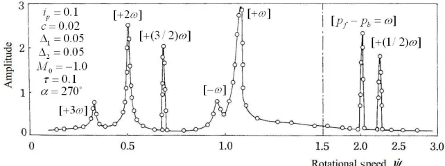
Fig. 3 shows the case of a horizontal rotor.
The symbol ○ represents the amplitude obtained
numerically. These values are connected smoothly by a full line. Various kinds of resonances occur in a wide rotational speed range due to a crack in view of a horizontal rotor. In addition to the harmonic resonance [pf = ω], the backward harmonic resonance
[pb = –ω], the super-harmonic resonances [pf = 2ω] and
[pf = 3ω], the sub-harmonic resonance [pf = (1/2)ω],
the combination resonance [ω = pf – pb] occur. This
is because the equilibrium position of the rotor shifts due to gravity and, as a result, the rotor system has both characteristics of more complex nonlinearity and more complex parametric excitation. Within all the above resonances, only harmonic resonances of these [pf = ω] can vary these characteristics significantly, depending on the angular position of the unbalance.
3 NON-STATIONARY OSCILLATIONS (A VERTICAL ROTOR)
This section explains the non-stationary characteristics of a cracked rotor. The governing motion equations
of it are given by putting M0 = 0 in Eq. (2). The
acceleration of a rotor is a constant λ, regardless of acceleration or deceleration. The angular position of the x'-axis can be obtained by:
ψ=( / )1 2λ2+ω ψ+ .
0
t t (4)
The response curves are shown by full lines in Fig. 4, and the curves are obtained numerically via the Adams method. The results for three kinds of
angular acceleration λ are also shown in Fig. 4. For
comparison, the amplitudes of steady-state oscillations (λ = 0) are shown by the symbol ○.
When the unbalance and the crack are on the same side, the result is shown in Fig. 4a. In this case, an unstable range exists. If the rotational speed of a rotor sweeps this unstable range, the large amplitude appears for the small angular acceleration λ. If they are on the opposite side, another result is shown in Fig. 4b. Since there no exists an unstable range, the amplitude is comparatively small regardless of any value of the angular acceleration λ. Fig. 5 shows that
the maximum amplitude rmax changes with the λ.
If the unbalance and the crack are on the same side, the cracked rotor cannot pass the main critical speed range due to having the very large amplitude when the angular acceleration λ is less than a certain critical value.
Different from the case of steady-state oscillations, the whirling speed and the rotational speed are different from each other, and the crack opens and closes repeatedly during the passage through the main critical speed. Therefore, it is imagined that the difference in the angular position of the unbalance does not influence the maximum amplitude in the case
Fig. 3. Amplitude variation curve of a horizontal cracked rotor
a) b)
of non-stationary oscillations. But Fig. 5 shows that
the maximum amplitude rmax changes remarkably due
to the direction of the unbalance. This means that the repetition of the opening and closing states do not occur frequently in the resonant range.
Fig. 5. Maximum amplitudes with acceleration λ
These results can be interpreted from the viewpoint of vibration diagnosis as follows: Since the maximum amplitude increases remarkably as shown in Fig. 4a, the appearance of a crack can be detected from the incremental amplitude. In contrast, if they are on the opposite side, it is very difficult to find it.
4 NON-STATIONARY OSCILLATIONS (A HORIZONTAL ROTOR)
In this section, non-stationary oscillations during the passage through the main critical speed are investigated when the rotor system is supported horizontally.
Time histories obtained by numerical integration are more complicated than that of a vertical rotor. A time history is shown in Fig. 6a for the case that the unbalance and the crack are on the same side. In addition, spectrums obtained by the complex-FFT method [20] are shown in Fig. 6b, in which the positive abscissa represents the forward whirling motion and the negative abscissa represents the backward whirling motion. Because of the rotor passing through the unstable range, the amplitude changes remarkably. Different from a harmonic component case of a vertical rotor, many frequency components exist in the spectrum diagram. In addition to the harmonic component between 1 and 1.5, a constant component, a backward harmonic component and a forward super-harmonic component with a frequency of two times the rotational speed coexist. Therefore, it is impossible to obtain the amplitude of the harmonic component by
calculating ( )θx 2+(θy)2. Instead, the complex-FFT method is used to process these data.
Based on the steady-state oscillations at the main critical speed of a cracked horizontal rotor [9] in our previous study, we obtained the following results: (a) in the case of the comparatively large unbalance, there exists an unstable range if the unbalance and the crack are on the same side and it disappears if they are on the opposite side; (b) in the case of the comparatively small unbalance, an unstable range appears regardless of the angular position of the unbalance. Therefore, we discuss non-stationary oscillations in the following two cases.
4.1 Case with a Large Unbalance
Fig. 7 shows amplitude variation curves with a comparatively large unbalance. The value of the unbalance is the same as that of Fig. 4. If the unbalance and the crack are on the same side, the maximum amplitudes are very large as shown in Fig. 7a. In contrast, if they are on the opposite side, the maximum amplitudes are small as shown in Fig. 7b.
a)
b)
Fig. 6. Non-stationary oscillation of a horizontal rotor; a) time history with non-stationary, and b) spectrum with non-stationary
can be similarly detected only if the unbalance and the crack are on the same side.
a)
b)
Fig. 7. Responses [+ω] of a horizontal rotor with a large ; a) unbalance within the crack side, and
b) unbalance without the crack side
Fig. 8. Responses [+ω] of a horizontal rotor with a small unbalance
4.2 Case with a Small Unbalance
Fig. 8 shows amplitude variation curves with a relatively small unbalance when the unbalance and the crack are on the opposite side. As seen from
the motion equations, the cracked rotor has both characteristics of a forced vibration system owing to the unbalance and a parametrical excited system owing to the breathing mechanism of the crack and the static deflection. If the rotor is well balanced, the effect of the former diminishes then the latter appears predominantly due to the breathing of the crack and the static deflection. As a result, in the steady-state oscillation, an unstable range always exists, no matter what the angular position of the unbalance. Therefore, the maximum amplitude of the non-stationary oscillation is large and it does not vary according to the angular position of the unbalance. Fig. 8 corresponds to Fig. 7b. These figures indicate that the amplitude becomes large when the unbalance is not large. The results consider that when the rotor system is well balanced, the occurrence of a crack can be monitored by the incremental amplitude to pass through the main critical speed with any directional unbalance.
5 FORWARD SUPER-HARMONIC AND FORWARD SUB-HARMONIC RESONANCES
5.1 Forward Super-harmonic Resonance of Order 2
In the neighbourhood of the rotational speed ψ = 0.52 in Fig. 3, twice the rotational speed is almost equal to a forward natural frequency and the super-harmonic resonance [pf = 2ω] occurs. This resonance does not
occur in a linear symmetrical rotor with a circular cross section if there is not a crack.
When the rotor passes through this resonance, the amplitude change is shown in Fig. 9. Because this super-harmonic resonance occurs more rarely than the harmonic resonance, comparatively large values of parameters Δ1 and Δ2 are used in the calculation.
The maximum amplitude is almost independent to the angular position of the unbalance and does not
decrease rapidly when the angular acceleration λ
increases. These characteristics show that this kind of resonance can be used as a correct signal for the occurrence of a crack.
5.2 Forward Sub-Harmonic Resonance of Order 1/2
In the neighbourhood of the rotational speed ψ = 2.23 in Fig. 3, the sub-harmonic resonance of order 1/2 [pf = 1/2ω] occurs. This resonance does not occur in a
linear symmetrical rotor if there is no crack. The amplitude variation curves are shown in Fig. 10a and the relationships between rmax and λ are shown in Fig.
resonance curves of this steady-state oscillation bifurcate from a trivial solution with the zero amplitude. In such a case, it is known that the amplitude variation curve can change remarkably according to the initial angular position of the
unbalance ψ0 [16]. This means that the maximum
amplitude takes various values with a given
acceleration λ. As a result, the relationship between
rmax and λ is represented by the shaded zone in Fig.
10b. Since this initial angular position cannot be controlled generally, the maximum amplitude of a non-stationary oscillation changes randomly for every operation. In Fig. 10b, the maximum amplitude
decreases rapidly with the angular acceleration λ
increasing. Based on the above characteristics, it is considered that this resonance is not suitable to be used as a signal of the occurrence of a crack in the non-stationary oscillations. Because this resonance does not always occur, the method is still not suitable for detecting a crack. In order to find the occurrence of a crack by observing this resonance, it is necessary to conduct several running tests with the small angular acceleration λ.
6 COMPARISON OF CHARACTERISTICS OF NON-STATIONARY OSCILLATIONS THROUGH VARIOUS RESONANCES
As mentioned above, the characteristics of non-stationary oscillations during the passage through resonances is different depending on the kind of
a) b)
Fig. 10. Amplitude curve of sub-harmonic resonance [+1/2ω]; a) resonance curve, and b) maximum amplitude rmax for λ
a) b)
Fig. 11. The relationships between rmax and λ;
resonance. Here, the maximum amplitude rmax
depending on the angular acceleration λ is summarized and compared.
Fig. 11a shows the case of the main critical speed of the horizontal rotor with a small unbalance. Since an unstable range exists at any directional unbalance, the maximum amplitude always becomes very large if the rotor passes through the main critical speed with a small angular acceleration. This means that, as mentioned above, the harmonic resonance can be used to detect a crack when the rotor is well balanced. When the unbalance is comparatively large (this case is not shown by the figure), the maximum amplitude during the passage through the main critical speed range does not increase due to the crack as the unbalance is located in the opposite side of a crack. Therefore, in this case, we must investigate the change of the maximum amplitude by changing the unbalance’s direction.
Fig. 11b shows the relationships between rmax and λ to pass through various kinds of resonances. In this figure, each plot representing the maximum amplitude is obtained by drawing a response curve like Fig. 4a. And these plots are connected smoothly by full lines. In order to investigate the quantitative difference among these resonances, the same parameter values are used. In the case of various harmonic resonances where the maximum amplitude depends on the initial angular position, a result for the same initial angular position is shown in this figure. From Fig. 11, the following results are confirmed: (a) if the angular acceleration λ is small, every kinds of resonance can be used as the signal of the occurrence of a crack; (b) if the angular acceleration λ is comparatively large, we
can use only the super-harmonic resonance [+2ω] as a
signal of the occurrence of a crack.
Fig. 12. Experimental system of a vertical rotor
7 EXPERIMENTAL SETUP
For safety, it was impossible to perform experiments on non-stationary oscillation using a horizontal rotor. Therefore, a vertical rotor system is used in experiments.
The experimental setup is shown in Fig. 12. A disk is mounted on the shaft at the positions of 200 mm or 150 mm below the middle of the elastic shaft that is simply supported using two double-row ball bearings at both shaft ends. The shaft is 700 mm in length and 12 mm in diameter. The diameter and the thickness of the disk are 481 mm and 5.5 mm, respectively. In order to make the same characteristics as in a transverse crack, a notch is made at the position 335 mm from the upper bearing, and it is filled with a part of the same dimensions as the notch as shown in Fig.
12. The notch has the width ω = 20 mm and the depth
h = 5 mm. The phase angle α in Fig. 12 represents
the angle between the crack and the unbalance. The deflections in the x- and y-directions are measured by position sensors.
8 EXPERIMENTAL RESULTS
8.1 Amplitude Variation during the Passage through the Resonance
The experimental setup where a disk is mounted on the positions of 200 mm below the middle of the elastic shaft is used.
8.1.1 Unbalance within the Crack Side
The unbalance is set α = 110° within the crack side.
The experiments are made for eight different angular accelerations λ = (75, 60, 50, 42.9, 37.5, 33, 30 and 27.3) rpm/s. The experimental results are represented by solid lines in Fig. 13. For comparison, the oscillation curve of the steady-state response is also
shown by the symbol ○. The unstable range drawn
by the hatching appears between ω = 1015 rpm and
ω = 1040 rpm when the rotor runs with a constant
speed. When the angular acceleration λ is 27.3 rpm/s, the maximum amplitude is large. When the angular
acceleration λ equals 75 rpm/s, the rotor passed the
8.1.2 Unbalance without the Crack Side
The unbalance is set α = 259° without the crack side. The experiments are made for six different angular
accelerations λ = (75, 60, 50, 42.9, 37.5 and 33)
rpm/s. The experimental results are shown by solid lines in Fig. 14. There is no unstable range under the steady-state oscillation. Therefore, when the rotor passes through the main critical speed, the maximum amplitude is always small. The experimental results shown in Fig. 14 agree qualitatively with the numerical results shown in Fig. 4b.
Fig. 13. Experimental results (unbalance within crack side)
Fig. 14. Experimental results (unbalance without crack side)
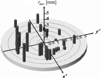
8.2 Relationship with Maximum Amplitude and the Unbalance Direction
The experimental setup in which a disk is mounted on the positions of 150 mm below the middle of the elastic shaft is used.
Initially, a static unbalance and a dynamic unbalance coexist in the experimental setup. Therefore, first, the rotor is sufficiently balanced. Then, a small mass is put on the disk in order to make the unbalance of the rotor. The maximum amplitude
is investigated for various directions and magnitudes of the unbalance. The experiments are done 24 times. The angular acceleration λ is fixed as λ = 37.5 rpm/s. The experimental results are shown in Fig. 15. Because it is difficult to identify the direction and the magnitude of an unbalance, the phase and the
amplitude of the steady-state oscillation at ω = 850
rpm is used instead of those of unbalance. This speed is lower than the main critical speed (ω = 930 rpm). To eliminate the effect of the initial bending, the phases and amplitudes are compensated by taking the relative phases and amplitudes to those at the rotational speed
ω = 90 rpm.
Fig. 15. Experimental statistical results (pass through the main critical speed with various cases)
The vertical axis of Fig. 15 represents the maximum amplitude to pass through the main critical speed. The crack is located in the negative y’ -direction. If the unbalance and the crack are on the
same side (that is, y' < 0), the maximum amplitude
9 DISCUSSIONS AND CONCLUSIONS
When the rotor starts up or shuts down, the rotational speed sweeps in a wide range under the rated speed. Therefore, if we observe some symptoms of the occurrence of a crack in non-stationary oscillations, the possibility of finding a crack will increase. For this purpose, this paper studied vibration characteristics to pass through a variety of resonances of a cracked rotor. The following characteristics are clarified. 1. In a vertical rotor system, the non-stationary
oscillation during passages through the main critical speed depends on the unbalance direction. If the unbalance and the crack are on the same side, the maximum amplitude will increase remarkably. However, if they are on the opposite side, the maximum amplitude does not increase. 2. In view of a horizontal rotor from simulation
results, the characteristics are similar to that of a vertical rotor if the unbalance is relatively large. However, when the unbalance is small, the maximum amplitude changes significantly for any directional unbalance because an unstable range appears.
3. When the rotor passes through the critical speeds of a backward harmonic resonance and a forward super-harmonic resonance, the maximum amplitude changes significantly with any acceleration.
4. In the cases of a super-sub-harmonic resonance of an order of 3/2, a sub-harmonic resonance of an order of 1/2 and a combination resonance, the maximum amplitude decrease rapidly as the acceleration increases. Considering these characteristics of non-stationary oscillations, the following method is recommended for finding a crack.
5. In the horizontal rotor with a comparatively small unbalance from simulation results, we can find a crack by noticing the incremental amplitude to pass through the main critical speed. In a vertical rotor or in a horizontal rotor with a large unbalance, there is a possibility of not finding a crack because the maximum amplitude does not increase due to a crack if the unbalance and the crack are on the opposite side.
6. Depending on the change of the maximum amplitude to pass through the critical speeds of the backward harmonic resonance and the forward super-harmonic resonance, we can find the appearance of a crack.
7. In the cases of the super-sub-harmonic resonance of an order of 3/2, and the sub-harmonic
resonance of an order of 1/2, we cannot always find the appearance of a crack.
10 ACKNOWLEDGMENTS
This work is supported by National Natural Science Foundation of China (11402170) and by Tianjin Natural Science Foundation of China (15JCYBJC19800, 16JCZDJC30400 and 17JCZDJC38500).
11 REFERENCES
[1] Varney, P., Green, I. (2013). Rotor dynamic crack diagnosis: distinguishing crack depth and location. Journal of Engineering for Gas Turbines and Power, vol. 135, no. 11, p. 345-355, DOI:10.1115/1.4025039.
[2] Silani, M., Ziaei-Rad, S., Talebi, H. (2013). Vibration analysis of rotating systems with open and breathing cracks. Applied Mathematical Modelling, vol. 37, no. 24, p. 9907-9921, DOI:10.1016/j.apm.2013.05.040.
[3] Lin, L., Chu, F. (2012). HHT-based AE characteristics of natural fatigue cracks in rotating shafts. Mechanical Systems and Signal Processing, vol. 26, p. 181-189, DOI:10.1016/j. ymssp.2011.07.017.
[4] Dong, G.M., Chen, J. (2009). Crack identification in a rotor with an open crack. Journal of Mechanical Science and Technology, vol. 23, no. 11, p. 2964-2972, DOI:10.1007/ s12206-009-0814-5.
[5] Ma, H., Feng, R., Pang, X., Song, R. Wen, B. (2015). Effects of tooth crack on vibration responses of a profile shifted gear rotor system. Journal of Mechanical Science and Technology, vol. 29, no. 10, p. 4093-4104, DOI:10.1007/s12206-015-0903-6.
[6] Darpe, A.K. (2007). A novel way to detect transverse surface crack in a rotating shaft. Journal of Sound and Vibration, vol. 305, no. 1-2, p. 151-171, DOI:10.1016/j.jsv.2007.03.070. [7] Wenhui, X., Yougang, T., Yushu, C. (2008). Analysis of
motion stability of the flexible rotor-bearing system with two unbalanced disks. Journal of Sound and Vibration, vol. 310, no. 1-2, p. 381-393, DOI:10.1016/j.jsv.2007.08.001.
[8] Zhu, C., Robb, D.A., Ewins, D.J. (2003). The dynamics of a cracked rotor with an active magnetic bearing. Journal of Sound and Vibration, vol. 265, no. 3, p. 469-487, DOI:10.1016/s0022-460x(03)00174-3.
[9] Ishida, Y., Inoue, T. (2006). Detection of a rotor crack using a harmonic excitation and nonlinear vibration analysis. Journal of Vibration and Acoustics, vol. 128, no. 6, p. 741-749, DOI:10.1115/1.2346693.
[10] Ferjaoui, N., Naimi, S., Chouchane, M. (2016). Bifurcation analysis of a flexible balanced cracked rotor–bearing system. Comptes Rendus Mécanique, vol. 344, no. 9, p. 661-671, DOI:10.1016/j.crme.2016.06.001.
[12] Ishida, Y., Hirokawa, K., Hirose, M. (1994). Vibrations of a cracked rotor 3/2-order super-subharmonic and 1/2-order subharmonic resonances. Transactions of the Japan Society of Mechanical Engineers Series C, vol. 60, no. 579, p. 3689-3696, DOI:10.1299/kikaic.60.3689. (in Japanese)
[13] Ishida Y., Hirokawa K. (1996). Internal resonances of a cracked rotor: major critical speed and critical speeds in precritical range. JSME International Journal. Series C, Dynamics, Control, Robotics, Design and Manufacturing, vol. 39, no. 2, p. 225-233, DOI:10.1299/jsmec1993.39.225.
[14] Guo, C., Al-Shudeifat, M.A., Yan, J., Bergman, L.A., McFarland, D.M., Butcher, E.A. (2013). Application of empirical mode decomposition to a Jeffcott rotor with a breathing crack. Journal of Sound and Vibration, vol. 332, no. 16, p. 3881-3892, DOI:10.1016/j.jsv.2013.02.031.
[15] Gómez, M.J., Castejón, C., Corral, E., García-Prada J.C. (2016). Analysis of the influence of crack location for diagnosis in rotating shafts based on 3 x energy. Mechanism and Machine Theory, vol. 103, p. 167-173, DOI:10.1016/j. mechmachtheory.2016.05.006.
[16] Ishida, Y., Ikeda, T., Yamamoto, T., et al. (1989). Nonstationary vibration of a rotating shaft with nonlinear spring characteristics during acceleration through a critical speed: A critical speed of a 1/2-order subharmonic oscillation. JSME International Journal. Series 3, Vibration, Control Engineering, Engineering for Industry, vol. 32, no. 4, p. 575-584, DOI:10.1299/jsmec1988.32.575.
[17] Li, B., Zhang, C., He, Z. (2012). HHT-based crack identification method for start-up rotor. Frontiers of Mechanical Engineering, vol. 7, no. 3, p. 300-304, DOI:10.1007/s11465-012-0328-1. [18] Li, B., Zhang, C.L. (2013). Hilbert-Huang Transform and Its
Application to Crack Identification for Start-Up Rotor. Advances in Vibration Engineering, vol. 12, no. 5, p. 459-473.
[19] Wang, K.S., Guo, D., Heyns, P.S. (2012). The application of order tracking for vibration analysis of a varying speed rotor with a propagating transverse crack. Engineering Failure Analysis, vol. 21, p. 91-101, DOI:10.1016/j. engfailanal.2011.11.020.

![Fig. 8. Responses [+ω] of a horizontal rotor with a small unbalance](https://thumb-us.123doks.com/thumbv2/123dok_us/8948974.1858342/6.581.71.284.109.615/fig-responses-w-horizontal-rotor-small-unbalance.webp)
![Fig. 9. Amplitude curve of super-harmonic resonance [+2ω]](https://thumb-us.123doks.com/thumbv2/123dok_us/8948974.1858342/7.581.60.266.74.228/fig-amplitude-curve-super-harmonic-resonance-w.webp)