University of New Orleans University of New Orleans
ScholarWorks@UNO
ScholarWorks@UNO
University of New Orleans Theses and
Dissertations Dissertations and Theses
5-15-2009
A Comparison Of Installation Methods And Maintenance
A Comparison Of Installation Methods And Maintenance
Practices Of Protected Side Armoring
Practices Of Protected Side Armoring
April J. Villa
University of New Orleans
Follow this and additional works at: https://scholarworks.uno.edu/td
Recommended Citation Recommended Citation
Villa, April J., "A Comparison Of Installation Methods And Maintenance Practices Of Protected Side Armoring" (2009). University of New Orleans Theses and Dissertations. 923.
https://scholarworks.uno.edu/td/923
This Thesis is protected by copyright and/or related rights. It has been brought to you by ScholarWorks@UNO with permission from the rights-holder(s). You are free to use this Thesis in any way that is permitted by the copyright and related rights legislation that applies to your use. For other uses you need to obtain permission from the rights-holder(s) directly, unless additional rights are indicated by a Creative Commons license in the record and/or on the work itself.
A Comparison Of Installation Methods And Maintenance Practices Of Protected Side Armoring
A Thesis
Submitted to the Graduate Faculty of the University of New Orleans in partial fulfillment of the requirements for the degree of
Master of Science in
The Department of Civil Engineering
By April J. Villa
ACKNOWLEDGEMENT
I would like to express my sincere gratitude to Dr. Mysore S. Nataraj for his technical guidance throughout my academic and professional career. Dr. Nataraj is more than my Major Professor but also my professional and life mentor. His direction and counsel is one that I seek and value. Through his courses I’ve gained not only knowledge of the course matter but also
professionalism from replicating his actions. He will be a life long mentor and professor.
I also would like to recognize Dr. John B. Grieshaber for his assistance, guidance, and instruction during my graduate studies at the University of New Orleans. He instilled good educational values in me, which was instrumental in the pursuit of my advanced studies. As my professional mentor, Dr. Grieshaber has gone above and beyond to coach me in my academic pursuits.
Thank you to Dr. Donald Barbe and Dr. Norma Jean Mattei for taking the time to serve on my thesis committee. I would like to thank Mr. Don Rawson, Dr. Steve Hughes, and the other senior engineers of the Armoring Team, New
Orleans District USACE for providing me with civil, geotechnical, hydraulic and armoring knowledge and guidance.
ABSTRACT
The IPET (Interagency Performance Evaluation Taskforce) Team’s significant finding is if the levees had armoring, the HSDRRS would have an element of resiliency. IPET defines resiliency as “The ability to withstand, without catastrophic failure…beyond those intended or estimated in the design. …resilience refers to the ability to withstand higher than designed water levels and overtopping without breaching” (USACE, 2007).
In the analysis of armoring products, two criterions usually govern. First, the ability for the armoring to resist overtopping velocity from storms greater than the 100 year authorized level. Second, does the product facilitate installation and maintenance post-Katrina? This thesis will help expand the knowledge base and hopefully the comfort level of armoring products so that we may widen our range of resources. Different products and their methods for installation and
TABLE OF CONTENTS
I. INTRODUCTION………. 1
a. Scope of Thesis……… 1
b. Location and Description of Study Site……… 4
II. BACKGROUND AND LITERATURE REVIEW………… 8
a. The New Orleans Area……… 8
b. Hurricanes Katrina and Rita……… 9
c. Main failure mechanisms………. 15
d. Interagency Performance Evaluation Taskforce (IPET).. 21
i. IPET Report-Summary of Findings………. 22
ii. IPET Report-Summary of Lessons Learned…… 24
e. USACE Authority……… 29
f. Information on the Armoring Team………. 33
III. METHODOLOGY OF INVESTIGATION……… 36
a. Installation………. 37
b. Maintenance……….. 38
IV. PROCEDURE AND RESULTS………... 39
a. Installation……… 39
i. Articulated Concrete Mats (ACM) -USACE product……….. 39
-Wester Excelsor product……….. 48
iv. Enkamat S- High Density Turf Reinforcement Mat (HDTMR)-Profile product………. 54
v. Grass only-Hydromulching……… 58
vi. Tapered Articulated Concrete Block (ACBs) - Contech product………. 62
b. Maintenance………. 64
V. COMPARISON OF PRODUCTS……….. 74
VI. RECOMMENDATION……….. 77
a. Installation Considerations……… 77
b. Maintenance Program Recommendations………. 78
VII. CONCLUSION……… 82
VIII. REFERENCES……… 84
IX. APPENDICES………. 85
a. Appendix A. Monthly Report of Installation Progress….. 86
b. Appendix B. Temperature and Rainfall Data………. 108
c. Appendix C. Equations used in gathering discharge and velocity rates……… 116
d. Appendix D. Products in Groups……… 123
List of Figures____________________________________________
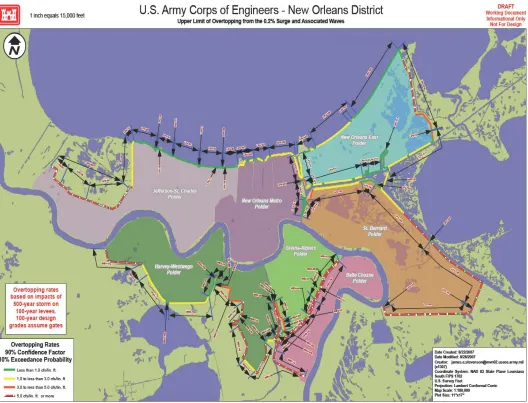
Figure 1: The Hurricane Storm Damage Risk Reduction System (HSDRRS) at 100 year elevations and with a 500 year storm event applied.
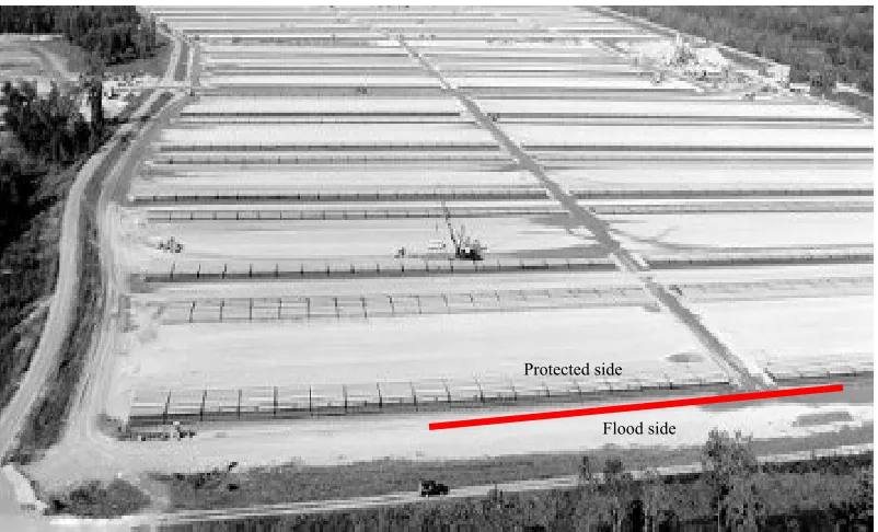
Figure 2: The St. Francisville Casting Field located 30 miles north of Baton Rouge and has been operating since 1961.
Figure 3: The red line in the photo represents the levee reach where the armoring products were installed.
Figure 4: Schematic of armoring product layout.
Figure 5: Hurricane Katrina’s path and strength according to NOAA. Figure 6: Hurricane Rita’s path and strength from www.wikipedia.org Figure 7: Stages of leeside erosion progression
Figure 8: Elevation showing flow down a typical levee. Figure 9: Typical levee under overflow conditions. Figure 10: Hewlett Curves (CIRIA 116, 1987).
Figure 11: Manufacture’s Installation Sequence (www.acfenvironmental.com). Figure 12: Anchored Reinforcement Vegetative System (ARVS) Step-by-step installation process.
Figure 13: ARVS staple installation layout.
Figure 14: Turf Reinforcement Mat (TRM) Step-by-step installation process Figure 15: Turf Reinforcement Mat (TRM) staple installation layout.
Figure 16: Manufacturer’s installation guide (www.westernexcelsior.com). Figure 17: Manufacturer’s installation guide (www.colbond-usa.com). Figure 18: Limiting velocities for plane grass.
Figure 20: Manufacturer’s installation guide (www.contech-cpi.com).
List of Photos____________________________________________
Photo 1: This photo was taken during Hurricane Katrina in New Orleans East at the Paris Rd. Bridge
Photo 2: This photo is of the same location in photo #1 showing the damages that were incurred. Scouring around the bridge supports was extensive. Photo 3: The damages to the floodwalls on the protected side when wave overtopping occurred are shown in this photo.
Photo 4: Armoring product #1 is a Propex product called Pyramat. It is a mat that is anchored with the system is the box photographed above to the right. Photo 5: Anchored Reinforced Vegetation System (ARVS) mat rolls lined up and trench is backfilled.
Photo 6: Workers are overlapping the mat by 6” and inserting staples to connect them to establish a unit. Photo 7: Manual drilling of the anchors.
Photo 8: Anchor cable is pulled in tension and crimp. Photo 9: Excess anchor cable is cut to eliminate stickup.
Photo 10: Due to manual anchor drilling being problematic, the drill bit is welded to the excavator bucket and the anchors are mechanically installed.
Photo 11: The ARVS is rolled out and anchors are spaced for placement.
Photo 12: Overview of the ARVS installed and the Western Excelsior mats start of roll out.
Photo 13: Western Excelsior mats placed is trench in the same fashion as the ARVS.
Photo 15: Only tools needed are this installation are staples and a hammer. Photo 16: Overview of the Western Excelsior Mat fully installed.
Photo 17: Section of the Enkamat Mat.
Photo 18: Start of Enkamat product installation.
Photo 19: The Enkamat S is being placed in the trench as the two previous geosynthetics.
Photo 20: Close-up of Enkamat S shows the grid that runs through the mat and the side that should be in contact with the ground should be the smoother side. Photo 21: The process of hydro-mulching must be evenly sprayed to cover the required area.
Photo 22: Hydro-mulching completed.
Photo 23: Here we see a filter fabric installed under the crushed stone.
Photo 24: Tampered Articulated Concrete Blocks (ACBs) from Armortec are installed.
Photo 25: Blocks are installed at the crown with the spreader bar attached to the excavator.
Photo 26: Four photos above show each product backfilled with about 1” topsoil. Photo 27: This photo captures the start of the maintenance process which was captured via video by local TV channels.
Photo 28: Grass cutting completed at the crown of the levee. Photo 29: Results of the ACBs after mowing.
Photo 30: Observation of insects that may cause armoring stability problems. Photo 31: Entire levee mowed.
Photo 32: Signs of the Enkamat under distress after mowing.
Photo 33: Result of ACB after overtopping and being underwater for several weeks.
Photo 35: More of the Enkamat exposed after the flooding.
Photo 36: With the facility being under water for several weeks, all the grass died leaving the reinforcement mats without reinforcement.
List of Tables____________________________________________
Table 1: Range of maximum velocities.
Table 2: Comparison of Installation Parameters. Table 3: Comparison of Maintenance Parameters.
List of Graphs____________________________________________
I.
INTRODUCTION
A. Scope of Thesis
The scope of this thesis will concentrate on the viable application and maintenance of armoring products to the New Orleans Hurricane Storm Damage Risk Reduction System (HSDRRS). The System is shown in Figure 1 and displays the overtopping rate at each project reach. A test section at the Army Corps of Engineers Concrete Mat Fabrication yard in St. Francisville, LA was implemented to determine which armoring products could be viable to the
HSDRRS. This location was considered because a ring levee protects the facility from annual flooding due to high river stages and overtopping could be
experienced. But most importantly, this levee is not part of the Hurricane Storm Damage Risk Reduction System (HSDRRS) and could be used without
compromising the integrity of the New Orleans System’s first line of defense in an event of a hurricane.
1. Can this product be installed and viable in the New Orleans Hurricane Storm Damage Risk Reduction System (HSDRRS)?
2. Will the Levee Boards be able to maintain the products once the ownership is transferred?
Figure 1: The Hurricane Storm Damage Risk Reduction System (HSDRRS) at 100 year elevations and with a 500 year storm event applied.
An Armoring Conference was organized in August 2007, where all known manufactures of armoring products, Levee Board Members and Engineers across all disciplines of USACE were invited to participate is a Round Table Discussion on the definition of armoring. Below is the definition of armoring that the
Definition of Armoring
“A natural or artificial material placed on or around a levee, floodwall, or other structure to reduce damage and protect from catastrophic damage (damage that compromises or undermines the structural integrity and design intent) when confronted with overflow and overtopping from a storm in excess of the design event. The minimum armoring for levees shall be grass. Armoring is only one of the
components of resilience.” (Armoring Team)
Or
B. Location and Description of Study Sites
As mentioned in the Introduction of this thesis and shown in Figure 2, the St. Francisville Concrete Mat Casting Field was selected for this test section for two main reasons:
1. A ring levee protects the facility from annual flooding due to high river stages and overtopping could be experienced.
2. But most importantly, this levee is not part of the Hurricane Storm Damage Risk Reduction System (HSDRRS) and could be used without compromising the integrity of the New Orleans System’s first line of defense in an event of a hurricane.
Figure 3: The red line in the photo represents the levee reach where the armoring products were installed.
These products will be monitored for maintenance concerns for 3 cycles. The full length of this study reach is 600’ as shown in Figure 3 by a red line. The
Protected side
five products and the grass only section is laid out in 100’ running lengths and are shown in the following order from right to left in Figure 4:
1. Articulated Concrete Mats (ACM)-USACE product
2. Anchored Reinforced Vegetation System (ARVS)- Propex product 3. PP12- Wester Excelsor product
4. Enkamat S- Profile product 5. Grass only-Hydromulching by
Figure 4: Schematic of armoring product layout. NOTE: ACB—Articulated Concrete Block
II.
BACKGROUND AND LITERATURE REVIEW
A.
The New Orleans Area
very little on the effects of surge and hydraulic loads as it relates to the duration of a storm in the Gulf and the surge and rainfall that can be generated from a variety of hurricane conditions. A Category 2 Hurricane versus a Category 4 Hurricane can have the same hydraulic effects on the Hurricane Protection System.
B. Hurricanes Katrina and Rita
According to NOAA (National Oceanic and Atmospheric Administration), the Saffir-Simpson Hurricane Scale is a 1-5 rating based on the hurricane's
present intensity. This is used to give an estimate of the potential property damage and flooding expected along the coast from a hurricane landfall. Wind speed is the determining factor in the scale, as storm surge values are highly dependent on the slope of the continental shelf and the shape of the coastline, in the landfall region. Note that all winds are using the U.S. 1-minute average. A Category 5 Hurricane contain winds greater than 155 mph and storm surge generally greater than 18 ft above normal.
Hurricane Katrina, a category 5 storm over the Gulf of Mexico, was still responsible for at least 81 billion dollars of property damage when it struck the U.S. Gulf Coast as a category 3. It is by far the costliest hurricane to ever strike the United States.
The Greater New Orleans continuous system of levees and floodwalls were put to the test during Hurricanes Katrina and Rita. These levees and
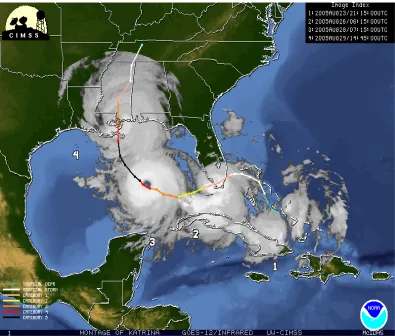
Saffir-Simpson Scale fails to measure the storm surge that comes with a Hurricane that was larger before making landfall. Hurricane Katrina was a Category 5 in the Gulf of Mexico but when it made landfall it was reduced to a Category 3. The storm’s path and strength is shown in the following NOAA graphic Figure 5.
Figure 5: Hurricane Katrina’s path and strength according to NOAA.
and surge conditions as shown in Photo 1 (captured during Hurricane Katrina in New Orleans East).
Photo 1: This photo was taken during Hurricane Katrina in New Orleans East at the Paris Rd. Bridge
Photo 2: This photo is of the same location in photo #1 showing the damages that were incurred. Scouring around the bridge supports was extensive.
Photo 3 shows the damages that occurred to the protected side on
floodwalls. One can see the sheetpile under the floodwall which indicates a scour hole about 5 feet deep. Unlike the earthen levees, which are sloped and therefore the free flow overtopping just ran its course down the slope, the floodwalls height creates a downpour of water that remains on the face of the floodwall whereby creating a concentrated scouring effect at the base of the floodwall stem. On average, the depth of scour on the protected side of the floodwalls that were overtopped ranged from 2-8 feet. This is a very large reduction in the
the wall. The design does not consider any loss of section due to overtopping and scouring.
Figure 6: Hurricane Rita’s path and strength from www.wikipedia.org
According to wikipedia, Hurricane Rita was the fourth-most intense Atlantic hurricane ever recorded and the most intense tropical cyclone ever observed in the Gulf of Mexico. Rita caused $11.3 billion in damage on the U.S. Gulf Coast in September 2005. Rita was the seventeenth named storm, tenth hurricane, fifth major hurricane, and third Category 5 hurricane of the historic 2005 Atlantic hurricane season.
surge caused extensive damage along the Louisiana and extreme southeastern Texas coasts and completely destroyed some coastal communities. The storm killed seven people directly; many others died in evacuations and from indirect effects.
New Orleans's levee system had already sustained heavy damage from Hurricane Katrina before Rita's outer bands of rain fell on the city. On Friday, September 23, the day before landfall, rising water due to Hurricane Rita poured through breaches in the patched Industrial Canal levee in New Orleans' devastated Ninth Ward, as reported by the Army Corps of Engineers. Water entered the Ninth Ward over two 32-foot (10 m) wide patches in the levee as of about 9 a.m. CDT on Friday, September 23. Water in the Ninth Ward was reported to be waist-deep at 11 a.m. CDT on Friday. By approximately 5 p.m. CDT, water had begun gushing through another patch in the London Avenue Canal into the surrounding Gentilly neighborhood. Some pumping stations were abandoned. By Saturday night, September 24, water from a 150-foot gap in the Industrial Canal levee flooded some areas of the Ninth Ward to eight feet deep. Louisiana Governor Kathleen Blanco reported that 700,000 homes lost power in 41 of the state's 64 parishes.
C. Main failure mechanisms
1.
Introduction
against overtopping. The structures were designed to perform with water elevations up to overtopping, but not beyond.
Levees were designed to provide protection up to the estimated water elevations for the Standard Project Hurricane (SPH). They were not designed to withstand overtopping. Overtopping generated very high velocities over the crest and back sides of the levees, leading to a high potential for scour and erosion. There was no armoring or uniform use of erosion resistant soils in the levee sections.
“Velocities from 10 to 15 ft/sec were calculated for the back sides of the levees along St. Bernard Parish, while the front sides of the levees experienced velocities of about one-third of those on the back side. Since erosion potential is related to the cube of velocities, the erosion potential on the back side of the levees was up to 10 times greater”, (USACE, 2006, pg. 1-6). USACE post hurricane inspection of these levees determined that all failures were caused by erosion of the back face.
highly vulnerable to erosion and breaching, especially those constructed by hydraulic fill.
The second area of significant difference dealt with the performance of the levees, specifically along the Mississippi River Gulf Outlet (MRGO).
Interagency Performance Evaluation Taskforce (IPET) analysis of this
phenomena included regional analysis of the surge and wave hydrographs along the levee sections, detailed modeling of wave action and currents in proximity to the levees and analysis of erosion process for the materials comprising the levees. The IPET analysis and physical evidence at the sites show that the systemic issue for levee performance was overtopping and the subsequent erosion from waves and ultimately surge. Where waves were incident perpendicular to the levees, the overtopping waves created velocities on the protected side of the levees up to three times those experienced on the front (water) exposed sides. This created a potential for erosion 10 times more severe on the crest and protected sides of the levees, (USACE, 2006).
2.
The protected side of levees
Stage A: Initial overtopping causes surface, sheet and rill erosion at weak spots that develops into a series of cascading overfalls. Erosion can be initiated at any point on the leeside slope. The highest forces develop from the backside slope down to the backside toe, and the crown is initially not exposed to these large hydraulic forces. The cascading overfalls develop into one large headcut that migrates from the slope to the crest such that the erosion width approximately matches the overtopping width.
Stage B: The headcut continues to migrate from the backside crest (crown) to the floodside crest.
Stage C: The crest drops as a breach begins to develop.
Stage D: The breach opening erodes out to the toe and the breach widens.
Stage A Stage B
Stage C Stage D
Figure 7: Stages of leeside erosion progression
macro-instability occurs when a part of the inner slope shifts along a deep slip circle. This may happen during floods when an increase of water pressure combines with a decrease in shear resistance in the slip circle. Infiltration by extreme precipitation, overflow or overtopping can saturate the top layer, increasing the risk of macro instability. This type of failure would most likely occur during stage B or C in Figure 7.
3.
Loading of levees
The different approaches to determine the loading exerted on the protected side of levees by overflow, overtopping or a combination of both is presented in the following paragraphs. Figure 8 illustrates a typical levee section and the flow patterns that can be seen when water elevation exceeds the levee crown elevation
a.) Overtopping
The discharge caused by wave overtopping will reach a maximum when the wave top reaches the levee and a minimum when the wave trough reaches the levee. For the design of the protected side armoring the critical discharge will be required as this will cause the normal loading. It is proposed to multiply the average discharge with a factor 3 to calculate the critical discharge.
The approach to assess the loading by overtopping is elaborately described in “Technical report wave run-up and wave overtopping at dikes”, (van der Meer, 2002). This recent report, which has a long history, is based on extensive
research and is used as a guideline for safety assessments and design of levees in The Netherlands.
b.) Overflow
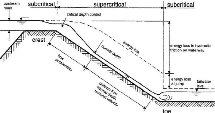
The second loading the system will experience is the flow velocity on the
protected side of a levee as a result of overflow. The super-critical flow on the
Figure 9: Typical levee under overflow conditions.
c.)
Combined overtopping and overflow
Combined overtopping and overflow is based on the introduction of an equivalent wash-over height to account for the extra discharge caused by wave action. When comparing the approach for overtopping with the approach for combined overtopping and overflow for a situation with no freeboard, ideally the results of both approaches should be more or less the same.
D. Interagency Performance Evaluation Taskforce
(IPET)
“Interagency Performance Evaluation Task Force: Strategic Overview
Performance Evaluation and Interim Results”
IPET’s Mission…“to provide credible and objective
scientific and engineering answers to fundamental
questions about the performance of the hurricane
protection and flood damage reduction system in the New
Orleans metropolitan area.”—Chief of Engineers
The Flood Protection System:
What were the design criteria for the pre-Katrina hurricane protection system, and did the design, as-built construction, and maintained condition meet these criteria? The Storm:
What were the storm surges and waves used as the basis of design, and how do these compare to the storm surges and waves generated by Hurricane Katrina? The Performance:
How did the floodwalls, levees, pumping stations, and drainage canals,
individually and acting as an integrated system, performing response to Hurricane Katrina, and why?
The Consequences:
What have been the societal-related consequences of the Katrina-related damage? The Risk:
Following the immediate repairs, what will be the quantifiable risk to New Orleans and vicinity from future hurricanes and tropical storms?
i. IPET Report-Summary of Findings
significantly below the design intent. The designs of the levee floodwall structures along the outfall canals were particularly inadequate. A series of incremental decisions that went from the original “barrier” plan to the “parallel protection” structures ultimately constructed systematically increased the inherent risk in the system without recognition or acknowledgment (USACE, June 2008, pg I-2).
The Storm: Katrina created record surge and wave conditions along the east side of New Orleans and the coast of Mississippi. Peak water levels along the
Plaquemines and St. Bernard levees and within the Inner Harbor Navigation Canal (IHNC) were significantly higher than the structures leading to massive overtopping and eventually breaching. Wave heights during Katrina were typically similar to those assumed for the design of the structures, except for Plaquemines Parish where they were higher than the design assumptions. Wave periods, however, were three times longer than the design assumptions,
The Performance: With the exception of four foundation design failures, all of the major breaches were caused by overtopping and subsequent erosion. Reduced protective elevations increased the amount of overtopping, erosion and
subsequent flooding, particularly in Orleans East. Ironically, the structures that ultimately breached performed as designed, providing protection until
overtopping occurred and then becoming vulnerable to catastrophic breaching. The levee-floodwall designs for the 17th Street and London Avenue Outfall Canals and IHNC were inadequate for the complex and challenging environment. In four cases the structures failed catastrophically prior to water reaching design elevations. A significant number of structures that were subjected to water levels beyond their design limits performed well. Typically, in the case of floodwalls, they represented more conservative design assumptions and, for levees, use of higher quality, less erodible materials (USACE, June 2008, pg I-2).
The Consequences: Approximately 80 percent of New Orleans was flooded, in many areas with depth of flooding exceeding 15 ft. The majority, approximately two-thirds overall in areas such as Orleans East Bank and St. Bernard, of the flooding and half of the economic losses can be attributed to water flowing
in residential areas. There was an additional loss of over $7 billion in public structures and utilities. The indirect consequences were equally disastrous. The breakdown in New Orleans’ social structure, loss of cultural heritage, and dramatically altered physical, economic, political, social, and psychological character of the area are unprecedented in the United States. In themselves, these create a formidable barrier to recovery. Where water depths were small, recovery has been almost complete. In areas where water depths were greater, little
recovery or reinvestment has taken place (USACE, June 2008, pg I-3).
The Risk: The prototype risk assessment process can identify the areas most vulnerable to future flooding and with the highest residual risk. Given more consistent levels of protection that will exist in the 2009 time frame, in many areas, level of risk is closely associated with the property values and population densities in the sub-basins and the elevation of the area (potential for deep
flooding) The exception is in the areas bounded by the IHNC where the reliability of protection will be lower because of legacy structures (types and elevation) and continued threat of high surge and wave conditions. Final risk results will be published at the completion of the risk analysis (USACE, June 2008, pg I-3).
ii. IPET Report-Summary of Lessons Learned
perform together. These methods need to be able to consider the performance of the system beyond the design criteria, including the life cycle value of resilience and redundancy in the design. Dynamic factors such as subsidence and changing hazard levels must be included. This requires an ability to develop and evaluate adaptive designs, protective concepts that allow planned augmentation to deal with expected changes as well as some ability to accommodate the unexpected. An accurate reference datum and monitoring of structure elevations, as well as the effective operation and maintenance of the hurricane protection system, are essential parts of this process. All assets that factor in the capability to provide protection, such as pump plants and closure structures, must be included in the overall analyses, even if they are not a formal part of the protection system. With rapid changes in new knowledge and engineering practice, it is essential to
continuously review and update technical guidance used in planning and design as well as providing an effective mechanism for the engineering community to adopt and mature new methods, The Standard Project Hurricane (SPH) methodology used to develop design criteria for the original system is outdated and should no longer be used. More flexible and robust probability-based methods are available that will provide better definition of the future hazard faced by protective
structures (USACE, June 2008, pg I-4).
shoreline comprised of both natural (marshes and ridges) and man-made barriers (levees and transportation corridors). These models need increased capabilities to accurately simulate the impact of barrier islands, marsh, and wetlands on surge and wave conditions. The interaction of the surge and wave conditions with structures such as levees and floodwalls requires special detailed modeling to accurately account for wave run up and overtopping, and to examine levee/wall response to dynamic loadings. Typically, very few measurements of waves and surge are made along the entire periphery of a HPS as part of a monitoring program. That was the case for this HPS. Large storms such as Katrina can cause failure of instrumentation intended to record the surge and wave environments created by the storm, and did so in this case. This creates a difficult problem for conducting analyses of a storm and its impacts. High-water marks were the only reference information reasonably available around the region for calibrating and validating surge modeling. Only a relatively small percentage of these marks (15 percent) were considered accurate enough for use, pointing to the need for more robust instrumentation that can survive storms as well as rigorous standards for evaluating the quality of high-water marks (USACE, June 2008, pg I-4).
present. The unanticipated failure mode defined in the IPET analysis for the outfall canal floodwalls is not the only potential failure mode for these structures not considered in the original designs. With the rapid expansion of knowledge and practice, it is necessary to frequently review the adequacy of existing
infrastructure in the context of that new knowledge and have processes in place to respond expeditiously to any performance limitations that arise. Resilience should be factored in to all designs to prevent catastrophic failures and to protect the integrity of the hurricane protection system itself. The maintained condition of the levees is an important factor in their overall performance and should be monitored more rigorously and through evaluations that extend beyond visual inspections (USACE, June 2008, pg I-5).
The Consequences: Even without the significant catastrophic breaching that occurred, the flooding and direct losses from Katrina would have been the worst in the history of the region. However, approximately half of the direct losses may have been averted if breaching had not occurred. This reduction in direct losses would likely have dramatically reduced the indirect consequences of the event. Together, this may have enabled a more rapid and systematic recovery. Resilience in the hurricane protection system would have provided that advantage.
environment proved very difficult. The scenario development accomplished to provide some insights into possible consequences of future hurricane events proved a feasible and valuable approach. Environmental losses were an essential component to the overall assessment of consequences, but they proved to be difficult to characterize beyond the short term, in part because of the already significant levels of contamination existing in the region. Not nearly enough information is available on the long-term impacts of saltwater intrusion and flooding on freshwater marshes, or the conditions and rates of recovery that can be expected (USACE, June 2008, pg I-5).
The Risk: Risk assessment provides a new and more comprehensive method to understand the inherent vulnerability for areas protected by complex protection systems and subjected to uncertain natural hazards. It provides a direct view into the sources of vulnerability, providing a valuable tool for public officials at all levels to focus resources and attention on the most serious problems and to seek solutions that reduce risk through both strengthening the reliability of the physical structures and reducing exposure of people and property to losses. Given a
relatively uniform level of reliability of the protection system, the relative risk values are largely related to elevation (below sea level) and the value of property or number of people who occupy those areas. The emergency response
E. USACE Authority
FACT SHEET—Selective Armoring of Levees
APPROPRIATIONS TITLE: Flood Control and Coastal EmergenciesSTUDY NAME/PROJECT: Armoring of Levees and Floodwalls- Lake Pontchartrain, Louisiana, and Vicinity (Hurricane Protection) (LPV), New Orleans to Venice, Louisiana (Hurricane Protection) (NOV), and West Bank and Vicinity, New Orleans, Louisiana (Hurricane Protection) (WBV) - (Plaquemines, St. Bernard, Orleans, Jefferson and St. Charles Parishes, Louisiana)
CONGRESSIONAL DIRECTION SOURCE: P.L. 109-234,Title II, Chapter 3, Flood Control and Coastal Emergencies, pages 38 (120 STAT. 455); and Title II, Chapter 3 of the Joint Explanatory Statement of the Committee of Conference, Flood Control and Coastal Emergencies, page 115.
DESCRIPTION OF ADDED WORK: P.L. 109-234 Title II, Chapter 3, Flood Control and Coastal Emergencies, page 38 (120 STAT. 455), hereinafter “4th Supplemental”, provides : “For an additional amount for ‘Flood Control and Coastal Emergencies’, as authorized by section 5 of the Act of August 18, 1941 (33 U.S.C. 701n), for necessary expenses relating to the consequences of
projects in southeast Louisiana to provide hurricane and storm damage reduction and flood damage reduction in the greater New Orleans and surrounding areas; . . . $170,000,000 shall be used for armoring critical elements of the New Orleans hurricane and storm damage reduction system: . . . “The Flood Control and Coastal Emergencies Section of Title II, Chapter 3 of the Joint Explanatory Statement of the Committee of Conference, Flood Control and Coastal
Emergencies, page 115, states “Funds totaling $3,145,024,000 are recommended to continue repairs to flood and storm damage reduction projects. These projects are to be funded at full Federal expense. . . . Additionally, the Conferees include: . . .$170,000,000 for levee and floodwall armoring; . . .”
DECISION DOCUMENT: Congress authorized this work in the absence of an agency decision document. A Project Description Document (PDD) will be developed to support the anticipated work.
the above hurricane protection projects. The critical areas include: transition points where levees and floodwalls abut; where pipelines cross levee alignments; at floodwalls, particularly those in densely populated areas; and where levees are directly exposed to large sections of open water (i.e. the New Orleans East and St. Bernard levees adjacent to Lake Borgne that suffered massive damage during Hurricane Katrina). Plans will vary with location and conditions and a process of prioritization will be developed to select the most critical areas for armoring within the projects.
for work to be performed under this feature of the 4th Supplemental will be performed utilizing a hurricane system wide approach that, to the extent possible, is coordinated with the potential plans that will be developed for the Louisiana Coastal Protection and Restoration (LaCPR) Project.
Implementation of the Selective Armoring authorized feature will be captured in the project specific Project Delivery Documents (PDDs) and will not require a separate PDD. Compliance with all environmental laws will be
completed during preparation of the project specific PDDs, prior to construction contract award.
F. INFORMATION ON THE ARMORING TEAM
Based on IPET’s findings and Congress’s Authority, the Armoring Team was formed with a dedicated core Project Management Team and a representative from each discipline across USACE, from engineering to real estate to environmental. The team was tasked to develop design criteria that would be applied consistently across the Hurricane Protection System. The team was also tasked to research products that would serve as armoring throughout the system. The Armoring Workshop was organized to bring the manufacturers together to help USACE with this research. The details of the workshop are described below.
purposes of the workshop was to showcase some of the latest materials, methods and techniques available for protecting levees and floodwalls from the effects of overtopping and erosion. Members of the design teams and other interested persons of the U.S. Corps of Engineers (USACE) were invited. Vendors and manufacturers were informed prior to the workshop that the focus of this particular event would be on the armoring of the protected sides of the levee systems. Of special interest were those products and services that could provide protection against a specific range of overflow water velocities and shear stress levels. The range of the hydraulic loading discussed had been identified following numerous post-Katrina studies and modeling.
Specific objectives for the workshop were to:
(1) Provide an opportunity for armoring-system vendors and manufacturers to showcase their products and answer questions specific to the New Orleans HSDRRS;
(2) Provide design and project management teams and consultants with an opportunity to dialogue with vendors and manufacturers of armoring systems regarding their composition, strength and application methods; and
The Armoring Team’s work offers the opportunity to examine risk at the sub-basins, basins (parishes), or system-wide levels. It also allows examination of the impact of changes in the character of the protection for a given reach,
providing a system-based approach to examine how alternative protection
measures can reduce risk. This can include relatively simple to very sophisticated measures. Simple measures might include armoring existing structures, elevating levees, and use of erosion-resistant materials, seepage berms, or relief wells. More sophisticated approaches could include replacing I-walls with T-walls and adding surge gates at the ends of the outfall canals. With limited modification, the analysis could include different types of approaches such as large surge barriers between Lake Pontchartrain and Lake Borgne.
The normal tolerable velocities of various armoring materials are set out in Figure 10 of CIRIA 116 (Hewlett, et al 1987). As a summary of the information in CIRIA 116, the recommended velocity ranges for various armoring materials are set out in
Table 1.
Table 1: Range of maximum velocities.
A.
Installation
Several variables were noted for comparison of each product to be
installed. The variables below represent the concerns that have been expressed by those involved in the Armoring Conference. The members involved ranged from Levee Board Members, Engineers, and product vendors. These variables are limited and are as follows:
1. A representative of each product installed was invited to witness the installation of their product.
2. The installers were given the standard installation instructions to install the products.
3. It was documented each time the installers incorrectly performed a step in the process.
4. It was also documented each time the product representatives corrected the installation process.
5. The number of laborers required for the installation. 6. The equipment needed to install the product.
7. The time it took to install 100’ of the product.
B. Maintenance
Several variables were noted for comparison of each product to be
maintained. The variables below represent the concerns that have been expressed by those involved in the Armoring Conference. The members involved ranged from Levee Board Members, Engineers, and product vendors. These variables are limited and are as follows:
1. The mowing blade was adjusted to cut the grass to leave 3” of blades left. This is the optimal length the grass should be cut. Any shorter, the roots would not be at its peak strength. 2. Special attention was placed on the ends/transitions of the
different materials during the mowing to watch for the ends being pulled up by the mower cutting blade.
3. Or if concrete, does the cutter blade clip the blocks where the edges are not flues.
4. Does exposed armoring become more exposed.
5. Levee Board Members (LBM) were present for the initial maintenance mowing.
6. Feedbacks from the LBM were documented and their
IV.
PROCEDURE AND RESULTS
A.
Installation
i. Articulated Concrete Mats (ACM)-USACE product The ACM segment of this test was installed prior to this thesis concept. Its placement was used as a reference to the rest of the products. The same
installation crew that installed the ACMs was employed to do this program so that we would have consistency over all the products. Their feedback is recorded in Tables 2 and 3 along with the other products that were observed during this period of installation.
ii. Anchored Reinforced Vegetation System (ARVS)- Propex product
Propex Pyramat Anchored Reinforced Vegetation System (ARVS) is the first product to be installed. This product is a patented woven technology composed of a unique, three-dimensional matrix of polypropylene yarns. These yarns are designed in a uniform, dimensionally stable and homogenous
outlets, structural backfills, utility cuts, potential traffic areas, abrasion, high-flow channels and/or areas where greater factors of safety are desired. Figure 11 shows the process of installing this product on a levee slope.
Figure 11: Manufacture’s Installation Sequence (www.acfenvironmental.com).
same excavated clay material and then compacted to manufactorer’s specification. The mat roll is rolled over the newly filled and compacted trench to create a closed tube like anchor system.
Photo 4: Armoring product #1 is a Propex product called Pyramat. It is a mat that is anchored with the system is the box photographed above to the right.
Photo 6: Workers are overlapping the mat by 6” and inserting staples to connect them to establish a unit.
Close to 16 workers during the height of construction and down to 6 when installation was minimal.
Step 1
Step 2
Step 3
Figure 13: ARVS staple installation layout.
Staples were hard to hammer in. They were too soft and flimsy. The levee material and compaction is very mature and is not a good representation of the conditions we will be facing with new levee construction. Staples were bent and poking out is areas where the soil was too hard. Again, in new levee
construction we anticipate that soil conditions to be soft and therefore this
installation difficulty should not be a concern, but in this test section the installers are not concerned with the staples perturbing out which could cause problems later in the maintenance stage of this study. This will be monitored closely for the effects of this improper installation. It still may be an issue in future levee
construction.
The installers were not monitored by the vendor representatives to place in appropriate locations therefore spacing was off. Anchors were also very difficult to install because of the mature soil conditions. The excavator was modified to
5’
6” overlap anchors staples
(5) drill bits were broken, 2 using the excavator and 3 using the hand held drill. The mat itself is very durable and easy to work with. It keeps its form and structure & provides a workable surface with surface traction for workers to maneuver. Its woven construction is very tight and there are concerns with this products ability to allow grass growth in-between the woven fabric. Anchor installation stopped due to broken bits with no more in reserve. The work was nearly a third complete and took 4 hours.
Photo 8: Anchor cable is pulled in tension and crimp.
Photo 10: Due to manual anchor drilling being problematic, the drill bit is welded to the excavator bucket and the anchors are mechanically installed.
iii. PP12-Turf Reinforcement Mat (TRM)-Wester Excelsor product
Western Excelsior mesh was installed in the trench, the trench was
backfilled and the mesh was rolled out using the same process and steps that were used during the Anchored Reinforced Vegetation System (ARVS) installation. The staples are still installed as the pervious product, but the only difference is that this system does not use anchors in its installation. This product is not as tightly woven as the ARVS. This product has a lesser strength than the previous. It took three (3) hours to completely install this product.
When asked which material they preferred to work with, the installers responded with the ARVS system because the surface of the mesh was very slippery on the Western Excelsior mesh. This surface made it very unsafe for the workers to casually walk on the mesh and the installation, although much faster than the ARVS, could have gone faster with less safety concerns on the forefront of the installers minds. The ends of the mesh unraveled and the mesh structure is not easily kept. The mesh is also not as consistent as the Woven fabric the ARVS system uses. Curious to see how this product holds up to the machine equipment during the topsoil placement over the various turf reinforcement mats (TRMs).
Photo 14: The trench is backfilled and the mat is rolled over the trench creating an anchor.
Figure 16 will illustrate the manufacturer’s installation guide for levee slope application. The process suggested in the guide was closely followed and easily implemented in this segment of installation.
Step 2
Step 3
Figure 14: Turf Reinforcement Mat (TRM) Step-by-step installation process.
Figure 15: Turf Reinforcement Mat (TRM) staple installation layout.
Photo 16: Overview of the Western Excelsior Mat fully installed. 5’
6” overlap staples
iv. Enkamat S- High Density Turf Reinforcement Mat (HDTMR)-Profile product
Enkamat is a flexible three-dimensional mat for erosion protection on the most varied slope types. The open Enkamat product is particularly suitable for use on steep dry slopes exposed to wind and rain and hence prone to erosion.
Enkamat creates an artificial root structure preventing soil eroding from steep slopes, river banks, landfill containments and other vulnerable areas. Once laid on slopes, Enkamat is seeded and filled with soil. Vegetation can then take root and develop easily.
Photo 18: Start of Enkamat product installation.
Photo 20: Close-up of Enkamat S shows the grid that runs through the mat and the side that should be in contact with the ground should be the smoother side.
Figure 17 demonstrates the installation process the manufacturer suggests for sequence of construction. The installers followed the guide easily and having a representative at the time of installation help insure that the quality of
v. Grass only-Hydromulching
In the following sections a brief description of the erosion resistance of turf is presented. In general a distinction is made between good, average and poor coverage. Coverage is, in most case, a measure of how much grass coverage is in a set portion with is measured in percent coverage, 100% is full and 0% is bare.
Erosion resistance against flow—
In Krystian W. Pilarczyk, Dikes and revetments, the following figure is presented,
which provides a basic idea on the erosion resistance of grass under influence of flow.
Figure 18: Limiting velocities for plane grass.
scalping the grass blades to stretch the duration of the following scheduled maintenance, the capacity to withstand high velocities is greatly reduced by 1.5 m/sec at the onset of the time test.
Erosion resistance against waves—
The following distinction on the erosion resistance of turf under influence of wave attack is presented:
a. Wave height < 0.4m:
• A good turf is generally not seriously damaged within a period of 1 to 2 days (the turf itself remains intact)
• A turf in a bad conditions is damaged quickly and holes up to 0.2m-0.4m depth develop within 24 hrs
• Turf of acceptable quality as a sandy subsoil may be effected severely within 24 hrs. Holes with a depth of 0.3m may develop.
b. 0.4m < Wave height < 1.0 m:
• An acceptable or good turf is affected only slightly within a period of 1 day or two days. The vegetation is damaged within 24 hrs.
• Turf in a bad condition is affected severely. Within 36 hrs holes with a depth of several decimeters may occur.
• An acceptable or good turf may yield within 15-20 hrs, under the condition that the subsoil is sufficiently resistant against erosion and no large damages are present.
• When large damages are present a turf of good or acceptable quality will yield within several hours.
• When the quality of the turf is bad, deep erosion takes place within several hours.
The rate of erosion is mainly determined by the quality of the turf and less by that of the subsoil.
Once all 4 armoring material were installed, the process of hydro-mulching took place on November 1, 2007. Hydro-hydro-mulching on all test areas consisted of approximately 1.2 acres of levee. The materials for this portion of the project consist of: 1 bag of hulled Bermuda grass seed, 1 bag of winter rye grass seed, and 54 bags of Enviroblend mulch. The hydro-mulching machine holds 100 gallons of water and was filled up 6 times, while adding 9 bags of much and 8lbs each of Bermuda and Rye grass seed per load. A rate of 2000lbs per acre was used. All armoring materials and test area were hydro-mulched on both sides of the levee project.
vi. Tapered Articulated Concrete Block (ACBs)- Contech product
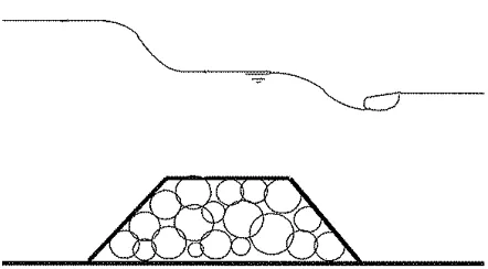
Armortec Articulated Concrete Blocks are being offloaded. Six trucks were needed to deliver the quantity needed for this test section. The levee was graded 8” deeper than the rest of the levee reach to accommodate the blocks thickness so that the final levee grade would be even throughout the entire 500’ study reach. All block dimensions are 17.4" x15.5". Each block is strung together by a continuous nylon rope to form a sheet which is 8’ x 20’.
Figure 19: Section of the Articulated Concrete Block with the crushed stone beneath it and the filter fabric between the subsoil and the crushed stone.
Off loading the sheets of ACB with spreader bar was very easy, but placement was very difficult with the equipment available. One crane was able to place a row of sheets along the trench near the toe and also a row above that. But for the rows past those, the crane was not able to reach to place the sheet that crossed over the levee crown and on the other side of the crown (the flood side of the levee section). The spreader bar was attached to the excavator and the work resumed. The time it took to place the first sheet was approximately 20 minutes with the crane. The sheets that lined up to it, which was placed by using the crane, took approximately 30 minutes. The remainder of the sheets that were installed by using the excavator took a lot of time lining up the blocks. Because the sheet of blocks are so flexible, which is good for conforming to the ground surface as it settles and compacts overtime in an uninformed way, this is
detrimental for installation purposes. Each time the sheet is not in line with the adjacent sheet already installed, the whole process must start over. The first sheet
Figure 20: Manufacturer’s installation guide (www.contech-cpi.com).
Figure 20 shows the step-by-step installation procedure. The procedure was altered slightly during this test to gather information on the installation of rock bedding to provide a drainage and filtration system for rain water.
Photo 25: Blocks are installed at the crown with the spreader bar attached to the excavator.
If this product was needed because of the overtopping rates that call for it, it is recommended that the proper equipment be used and that a large enough work area be used. Each sheet installed was 8’ x 20’ and weights 100 psf for a total of 16,000 pounds per sheet. The offloading requires at least the area for an 18 wheeler and a backhoe.
elevation needed. With the cost of clay material, in the post-Katrina market, this could be significant cost savings.
Photo 26: Four photos above show each product backfilled with about 1” topsoil.
In some cases topsoil was seen to be more than 1”. This could be a problem with the TRMs. The grass roots may not reach far enough down to merge with the TRM and bonding. This is an ideal situation for maintenance though. As for the ACB, the depth of topsoil is not as large of a concern.
During these months, the temperature and rain fall data were gathered to correlate the elements with the grass growth inspected and are located in Appendix B.
Comparisons of the products to one another will be discussed in the Comparison segment of this thesis. This comparison is limited to feedback from the installers, results of the installation, workability and cost.
B. Maintenance
As anticipated, the first maintenance cut occurred in March 2008 and the photos in this section show a successful first mowing pass. All the parish levee board members present at the Armoring Conference were invited to witness the maintenance of this test section. They have extensive experience with the hazards and problems that these products can pose to people, maintenance machines and the levee structure itself. Their recommendations will be covered in the
Photo 28: Grass cutting completed at the crown of the levee. Photo 29: Results of the ACBs after mowing.
Photo 30: Observation of insects that may cause armoring stability problems.
Photo 32: Signs of the Enkamat under distress after mowing. Photo 33: Result of ACB after overtopping and being under
water for several weeks.
On April 12th, the St. Francisville Facility was
Photo 34: Grass only section of the levee alignment shows nearly 2 feet of scouring at the crown of the levee.
Photo 35: More of the Enkamat exposed after the flooding.
V.
COMPARISON OF PRODUCTS
Tables 2 and 3 summaries the results after monitoring the installation of each product, documenting the process of grass growth to the point of mowing, witnessing the initial maintenance cut with the Levee Board Members (LBM) and implementing their feedback, and supervising the overtopping event that surprised this experiment.
The top three parameters for installation are labor, equipment and time. The other parameters can easily be addressed by sharing with the manufacturers our finding on how to make their instructions user-friendly. With labor, time and equipment being the top parameters, this could add considerable cost and time to the projects. The ARVS is the most labor intensive and time consuming with regards to installation. The ACB needs the most in equipment for installation. Because of the weight and size of the ACB a crane and an 18 wheel truck is needed were as the others only need a regular work truck for transportation and no crane.
The given parameters for maintenance are not as clear cut as that for installation. Table 3 shows that the Enkamat is the worst with respect to maintenance. During the overtopping event the top soil eroded more and more than what was observed during the mowing.
INSTALLATION
PARAMETERS representative present
standard installation
provided
installers incorrectly performed a step
representatives corrected the
installation process of laborers number equipment needed
time (hr)
Articulated Concrete Block (ACB)
yes yes yes yes 6 backhoe w/
spreader bar 8
Grass Only yes yes no no 3 none 1
Enkamat yes yes yes no 6 rubber mallet 5
Western Excelsior no no no no 6 rubber mallet 3
Anchored Reinforced Vegetative System (ARVS)
yes yes yes yes 16
drill 3' drill bit rubber mallet
12
Articulated Concrete Mats (ACM)
yes no no no 6 backhoe w/
spreader bar 6
MAINTENANCE
PARAMETERS mowing
3” depth problems with transitions cutter blade concrete clip exposed armoring more exposed
(LBM) present for initial
mowing
recommendations included in future
level of overtopping resistance Articulated Concrete Block (ACB)
yes yes yes yes yes yes* high
Grass Only yes no N/A no yes none low
Enkamat yes yes N/A yes yes none low
Western Excelsior yes no N/A no yes none low
Anchored Reinforced Vegetative System (ARVS)
yes no N/A yes yes yes** mid
Articulated Concrete Mats (ACM)
yes no no no yes none high
* Bedding be excluded from the steps is possible. Gravel bedding may cause problems during maintenance.
** Anchors may cause injuries to pedestrians in populated areas where levee is used for recreation.
VI.
RECOMMENDATION
a. Installation Considerations
1. Impact of the armor on the design of the existing structure:
Details connecting to existing floodwalls should be considered and recommendations from the manufacturer should be
implemented.
2. Site access and maneuverability requirements:
With the requirement required to install the concrete products due to its weight and size, these products should not be used in confined work areas.
3. Quality of transitions is important in keeping the armor material from being exposed to the mower blades. Intense quality control from the product representatives should be applied in these areas during installation.
4. Safety requirements maybe important in areas where levees are used frequently for recreation.
b. Maintenance Program Recommendations
The Armoring is made up of two major components: the armoring and the hydraulic mulch. A proper maintenance program is necessary to ensure that the function of the armoring system will perform as it was designed - minimizing erosion and protecting the established vegetation during extreme storm events. The following five (5) areas have been identified as important when it comes to the maintenance program. These include Initial Installation, Vegetation
Establishment (and Density), Fertilization, Monitoring Performance and Mowing.
1. Initial Installation
2. Vegetation Establishment
The second most important part is to establish the vegetation in order to achieve maximum performance of the armoring. This is where the second component, hydraulic mulch greatly enhances the establishment of vegetation. Hydraulic mulch creates an erosion control layer to protect the underlying soils and it will retain 15 times its weight in moisture to ensure vegetation grows even during dry spells. The three parts for seed germination and establishment of vegetation include temperature, moisture and soil makeup. Obviously
3. Monitoring Performance
A qualified inspector should perform periodic monitoring. This should particularly be done after storm events to check for erosion, scour, debris or any significant sediment accumulations. If erosion or scour has occurred, it is recommended that the trouble area be reworked by placing the soil and re-seeding. Debris and any significant sediment accumulations should be removed to reduce restriction to vegetation growth. The levee slopes should also be reviewed to ensure proper slope stability. The monitoring program should also identify the condition of the vegetation growth and density, as well as, signs of stress caused by weather conditions or flow events.
4. Mowing
5. Fertilization
VII.
CONCLUSION
The main conclusion is that the knowledge on armoring of crest and leeside of levees, floodwalls and transitions is very limited. However, based on a literature survey and for a limited number of conditions, approaches have been presented which could be used for design of armor. The questions to answer as the scope of this thesis:
1. Can this product be installed and viable in the New Orleans Hurricane Storm Damage Risk Reduction System (HSDRRS)?
2. Will the Levee Boards be able to maintain the products once the ownership is transferred?
The answer is that each product has its place in the system. Areas of the system will need robust products like Articulated Concrete Blocks and others areas will be suited for grass only. Conversely, the Levee Boards will need further guidance in how their maintenance practices will be renewed with the presences of these armored levees in the protection system.
This thesis acknowledges that elaborate studies and investigations are required to fill in the knowledge gaps and develop the preliminary approaches in general design tools.
Seven Steps for Successful Armoring Selections
1. Select applications
2. Determine functional longevity
3. Anticipate climate (arid, semi-arid, or temperate) 4. Understand traditional solution
5. Predict non-hydraulic stresses (maintenance stresses) 6. Know vegetation type
VIII.
REFERENCES
1. Richard D. Knabb, Daniel P. Brown, Jamie R. Rhome, NHC Rita Report,
2007.
2. Performance and evaluation of the New Orleans and Southeast Louisiana Hurricane Protection System. Final Report of the Interagency
Performance Evaluation Task Force, USACE, 2007.
3. “Overview of Hydraulic and Armor Design of Overtopped Levees and Floodwalls”, Jurriaan de Jong, DRAFT REPORT Royal Haskoning, 2006. 4. Steven A. Hughes, Donald L. Ward, Johannes L. Wibowo, Landris T. Lee,
Protection alternatives for levees and floodwalls in southeast Louisiana: phase one evaluation, 2006.
5. van der Meer, J.W., Technical Advisory Committee on Flood Defense,
Technical report wave run-up and wave overtopping at dikes,
Delft, May 2002.
6. Krystian W. Pilarczyk, Dikes and revetments, 1998
7. "Elevations For Design of Hurricane Protection Levees and Structures", Lake Pontchartrain, Louisiana and Vicinity Hurricane Protection Project and West Bank and Vicinity, Hurricane Protection Project, US Army Corps of Engineers, New Orleans District, October 2007.
8. Hurricane and Storm Damage Risk Reduction System, “Protected Side Armoring Manual”, USACE DRAFT Report, 2008.
9. Performance Evaluation of the New Orleans and Southeast Louisiana Hurricane Protection System. Final Draft Report of the Interagency Performance Evaluation Task Force: Volume I – Executive Summary and Overview, USACE, June 2006.
10. Performance Evaluation of the New Orleans and Southeast Louisiana Hurricane Protection System. Final Report of the Interagency Performance Evaluation Task Force: Volume I – Executive Summary and Overview, USACE, June 2008.