Development of agricultural bionic four-legged robot: Effect of head
movement adjustment on the stability of goats
Fu Zhang
1,2,3*,
Yafei Wang
1,
Shuai Teng
1,
Limin Zheng
1,
Jiajia Wang
1,
Zijun Chen
1(1. College of Equipment Agricultural Engineering, Henan University of Science and Technology, Luoyang, 471003, China; 2. Collaborative Innovation Center of Machinery Equipment Advanced Manufacturing of Henan Province, Luoyang 471003, China;
3. Henan International Joint Laboratory of Intelligent Agricultural Equipment Technology, Luoyang 471003, China)
Abstract: The four-legged bionic robot for agriculture has been one of the hotspots in the field of robotics. The farmland environment is complex, and the balance requirement of quadruped bionic robot is higher. However, head adjustment is a key factor affecting the balance of quadruped animals. Based on this, this study takes the four-legged animal goat as an example to investigate the effect of goat head movement adjustment on the balance of goat. In this study, the head and neck of goats were simplified to a two-link model. The kinematics model was established by D-H method. MATLAB software was used to solve it. Origin software was used to draw the movement track of the center of mass of the head. The center of mass movement of the head is a quarter ellipse. Then, the goat walking experiments were carried out on the different slopes (0°, 5°, 10°, 15°, 20°, 25°, 30°, 35° and 40°). MATLAB software was used to fit the movement data of goat head. The movement of the center of mass of the goat's head corresponds to Fourier 6. The result is: the determination coefficient is 0.8629, and the mean variance is 0.019. When the slope gradient gradually increases, the volatility gradually increases and is cyclical. The results of this study verify the rationality of the four-legged bionic mechanism under various parameters and reveal the mechanism of goat walking with an appendage at the head.
Keywords: bionic four-legged robot, slope, head, center of mass, trajectory, balance DOI: 10.25165/j.ijabe.20191204.4287
Citation: Zhang F, Wang Y F, Teng S, Zheng L M, Wang J J, Chen Z J. Development of agricultural bionic four-legged
robot: Effect of head movement adjustment on the stability of goats. Int J Agric & Biol Eng, 2019; 12(4): 10–15.
1 Introduction
Bionics is a special capability to imitate biological functions and uses biological structure and functional principles to develop relevant equipment of science and technology. Bionics is a new interdisciplinary field and provides a new idea for the study animal and imitates of the overall structure, movement, and control[1-7].
Some scholars studied the leaping movement structure, shape, and characteristics of the biological system of a kangaroo and its movement mechanism by analyzing video data of kangaroo jumping. The mechanism of kimono jumping robot was proposed, and the kinematics and dynamics of bionic jumping were studied. The theory and design method of the kangaroo jumping robot were also established[8-10]. Some scholars investigated the mechanism
of the movement between the head and tail adjusting device and the robot body on the basis of kinetic analysis and bionics observation. They also proposed the control strategy of the head and tail adjusting device. Their results showed that the use of head and
Received date: 2018-04-01 Accepted date: 2019-04-24
Biographies: Yafei Wang: Master Student, research interest: the intelligent
agricultural equipment and technology, Email: [email protected]; Shuai Teng, Master student, research interest: the intelligent agricultural equipment and technology, Email: [email protected]; Limin Zheng: Master Student, research interest: the intelligent agricultural equipmentand technology, Email: [email protected]; Jiajia Wang: PhD, Lecturer, research interest: Biomechanics and bionic, Email: [email protected]; Zijun Chen: research interest: the intelligent agricultural equipment and technology, Email: [email protected].
*Corresponding author: Fu Zhang, PhD, Professor, Assistant Dean, research
interests: the biomimetic technology and the intelligent agricultural equipment. College of Equipment Agricultural Engineering, Henan University of Science and Technology, Luoyang, 471003, China. Email: [email protected].
tail as the adjustment device to improve the dynamic performance of four-legged robot exerts a positive effect and provides a basis for the study of head-regulated movement[11,12]. Tian et al.[13]
installed a centroid adjustment device in the quadruped robot body, which can attain two-dimensional movement in the horizontal plane, by planning the trajectory of the center of mass to keep it inside the supporting polygon. This system achieves a stable gait movement during walking, thereby providing the basis for studying the center of gravity control of goats. Zhang et al.[14,15] explored the gait movement and mechanism of a goat on a slope, designed the walking mechanism of the goat, and carried out dynamic simulation analysis on the basis of the said walking mechanism. Their result indicated that the change in gait movement during walking is mainly attained by adjusting the position of center of gravity. Briggs et al.[16] of the Massachusetts Institute of
Technology Biomimetic Robot Labs observed that the tail of a cheetah quickly turns from one side to the other to adjust the balance of the trunk in sharp turns. A simple torque controller was designed to analyze the law of the interaction between the tail and torso, and the attitude adjustment in the floating state was realized through simulation. They proved that the swing of the tail can make the robot resist disturbance. Some researchers designed the tail of single leg model of kangaroo jumping robot on the basis of the movement structure and jumping characteristics of a kangaroo and in consideration of the effect of the tail on its movement posture[17]. The leg length and centroid change of the
of a cat move its tail to respond to movement and that the results showed that the cat can quickly by analyzing the training videos of four cats animal can be retained by adjusting the tail on the beam[18-20].
The fitting of the centroid movement of quadruped head on a slope and the change in the centroid has been rarely explored. The effect of the movement of the appendage on four-legged animals in a slope also requires comprehensive understanding. In this study, the trajectory of the head centroid movement of a goat on a slope is measured and its influence on the stability is analyzed to solve the problem of irregular ground walking of current small machinery[21-27].
2 Study on goat head movement
2.1 Analysis of kinematics model of goat head
To study the movement characteristics of the head during walking of goats, the head and neck of the goat were simplified into two linkage models, as shown in Figure 1. The head and neck links are represented as L2 and L1. The uphill direction is x0.
It’s going to be y0 perpendicular to the slope. (x0, y0) is the base
frame, fixed on the base. (xt, yt), (x1, y1), (x2, y2) are the conjoined
coordinate system, which are fixed on link L2 and link L1, and then
move together. Joint Angle clockwise is negative, counterclockwise is positive. O is the connection between the body and the neck, A is the connection between the neck and the head, and the center of mass of the head is t.
Figure 1 Goat head simplified model
The kinematics model of goat head is established by the D-H method.
1 1 1 1 1
1
( , ) (0,0, ) ( ,0,0)
( , )
n
n n n n n
n
T A Rot zθ Tran d Tran α
Rot xα
+ + + + +
+
= = × × ×
1 1 1 1 1 1 1
1 1 1 1 1 1 1
1
1 1 1
cos sin cos sin sin cos
sin cos cos cos sin sin
0 sin cos
0 0 0 1
n n n n n n n
n n n n n n n
n
n n n
θ θ α θ α a θ
θ θ α θ α a θ
A
α α d
+ + + + + + + + + + + + + + + + + + − ⎡ ⎤ ⎢ − ⎥ ⎢ ⎥ =⎢ ⎥ ⎢ ⎥ ⎣ ⎦
1 2 1
1 2 3 1 2 3
R R n
H n n
T = T T T −T =A A A A
L L (1) Where n is the number of joints with the assumption that z0, z1,
and z2 are perpendicular. The homogeneous rotation
transformation matrix from (x0, y0, z0) to (x1, y1, z1) and the
homogeneous rotation transformation matrix from (x1, y1, z1) to (x2,
y2, z2) are as follows:
1 1
1 1
0 1
cos sin 0 0
sin cos 0 0
0 0 1 0
0 0 0 1
θ θ θ θ T − ⎡ ⎤ ⎢ ⎥ ⎢ ⎥ =⎢ ⎥ ⎢ ⎥ ⎣ ⎦ ,
2 2 1
2 2
1 2
cos sin 0
sin cos 0 0
0 0 1 0
0 0 0 1
θ θ L
θ θ T − ⎡ ⎤ ⎢ ⎥ ⎢ ⎥ =⎢ ⎥ ⎢ ⎥ ⎣ ⎦ (2) The homogeneous rotation transformation matrix from (x0, y0,
z0)to (x2, y2, z2) is:
0 0 1
2 1 2
1 1 2 2 1
1 1 2 2
1 2 1 2 1 1
1 2 1 2 1 1 1
cos sin 0 0 cos sin 0
sin cos 0 0 sin cos 0 0
0 0 1 0 0 0 1 0
0 0 0 1 0 0 0 1
cos( ) sin( ) 0 cos
sin( ) cos( ) 0 sin
0 0 1 0
0 0 0 1
T T T
θ θ θ θ L
θ θ θ θ
θ θ θ θ L θ
θ θ θ θ L θ
= ⋅ − − ⎡ ⎤ ⎡ ⎤ ⎢ ⎥ ⎢ ⎥ ⎢ ⎥ ⎢ ⎥ =⎢ ⎥ ⎢⋅ ⎥ ⎢ ⎥ ⎢ ⎥ ⎣ ⎦ ⎣ ⎦ + − + ⎡ ⎤ ⎢ + + ⎥ ⎢ ⎥ =⎢ ⎥ ⎢ ⎥ ⎣ ⎦ (3)
Then, the position vector of the end of the connecting rod 2 and the midline intersects at point t in the base coordinate system are as follows:
(
)
(
)
0 0 2
2
2
1 2 1 2 1 1
1 2 1 2 1 1 1
2
1 1 1 2
2
1 1 1 2
cos( ) sin( ) 0 cos
2
sin( ) cos( ) 0 sin 0
0 0 1 0 0
0 0 0 1 1
cos cos 2 sin sin 2 1 1 t t t
t T t
L
θ θ θ θ L θ
θ θ θ θ L θ
L
L θ θ θ x
L y
L θ θ θ
z o = ⋅ ⎡ ⎤ + − + ⎡ ⎤ ⎢ ⎥ ⎢ + + ⎥ ⎢ ⎥ ⎢ ⎥ =⎢ ⋅ ⎢ ⎥ ⎥ ⎢ ⎥ ⎢ ⎥ ⎢ ⎥ ⎣ ⎦ ⎢ ⎥⎣ ⎦ ⎡ + + ⎤ ⎢ ⎥ ⎡ ⎤ ⎢ ⎥ ⎢ ⎥ ⎢ + + ⎥ ⎢ ⎥ =⎢ ⎥ ⎢ ⎥⋅ ⎢ ⎥ ⎢ ⎥ ⎢ ⎥ ⎣ ⎦ ⎢ ⎥ ⎣ ⎦ (4)
(
)
(
)
21 1 1 2
2
1 1 1 2
cos cos 2 sin sin 2 t t L
x L θ θ θ
L
y L θ θ θ
⎧ = + + ⎪⎪ ⎨ ⎪ = + + ⎪⎩ (5)
Thus, the head center coordinates are:
(
)
(
)
2
1 1 1 2
2
1 1 1 2
cos cos 2 ( , ) sin sin 2 t t L
L θ θ θ
x y
L
L θ θ θ
⎛ + + ⎞ ⎜ ⎟ ⎜ ⎟ = ⎜ + + ⎟ ⎜ ⎟ ⎝ ⎠ (6)
2.2 Parameter of goat head movement model
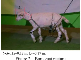
Three-month-old female Boer goats were used in the test. The average length of head and neck are L2 and L1 respectively, as
shown in Figure 2.
Note: L1=0.12 m, L2=0.17 m.
Figure 2 Bore goat picture
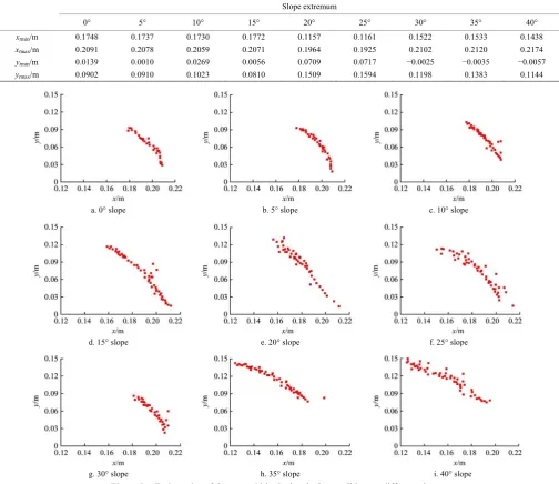
The length of its neck and head were input to the model. When the goat was walking in different slopes, the trajectory of the head center of mass relative to the head and neck can be calculated via MATLAB. The extreme values of the track coordinates (maximum and minimum values in the coordinates) were shown in Table 1.
In the model of the head movementof the goat walking on a slope, the goat neck L1, the length of the head L2, and the time
obtain the goat head trajectory (xt, yt). In the model, the coordinate ORIGIN of the reference coordinate system is the connection point of head and neck. At any time, the centroid
position of the goat is represented by (xt, yt), and ORIGIN software is used to draw the trajectory of the head centroid movement of the goat walking on different slopes (Figure 3).
Table 1 Extreme values of the trajectory coordinates
Slope extremum
0° 5° 10° 15° 20° 25° 30° 35° 40°
xtmin/m 0.1748 0.1737 0.1730 0.1772 0.1157 0.1161 0.1522 0.1533 0.1438
xtmax/m 0.2091 0.2078 0.2059 0.2071 0.1964 0.1925 0.2102 0.2120 0.2174
ytmin/m 0.0139 0.0010 0.0269 0.0056 0.0709 0.0717 −0.0025 −0.0035 −0.0057
ytmax/m 0.0902 0.0910 0.1023 0.0810 0.1509 0.1594 0.1198 0.1383 0.1144
a. 0° slope b. 5° slope c. 10° slope
d. 15° slope e. 20° slope f. 25° slope
g. 30° slope h. 35° slope i. 40° slope
Figure 3 Trajectories of the centroid in the head when walking on different slopes
3 Analysis of goat walking test
3.1 Experimental equipment
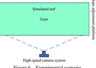
The equipment used in this test: the high-speed camera system (Figure 4), which includes high-speed camera, light source, and Phantom Camera Control Application software; the slope adjustment system (Figure 5), which includes a slope adjustment platform and a visual control interface.
a. High-speed camera b. Light source Figure 4 High-speed camera system
a. Slope adjustment platform b. Visual control interface Figure 5 Slope adjustment system
3.2 Experiment methods
Framing range, shooting distance, and aperture and focal length hardware conditions were adjusted as well to ensure that the main axis of the lens aimed at the center of the goat’s movement and as close as possible to the goat's motion plane to obtain a clear image of the goat. The high-speed camera was adjusted for the shooting speed and different slopes of the goat movement to adapt. The motion sequence images of the goat on different slopes were recorded (0°, 5°, 10°, 15°, 20°, 25°, 30°, 35° and 40°) and stored in a computer. The goat movement data was analyzed by PCC image software. The experimental scenario was shown in Figure 6.
Figure 6 Experimental scenario
3.3 Processing of experiment data
The average of the data is obtained by repeating the slope test several times. Phantom Camera Control software is used to measure the timing of the angle between the head and neck of the goat and between the neck of the goat and the slope on different slopes in solving the balance problem of agricultural machinery. High-speed photography PCC software is used to measure the
angles of the head and neck and the neck and the slope, as shown in Figure 7.
Figure 7 Process of test
3.4 Test results
When the goat walks on the slope of the map, the direction of the body is zero coordinate point, parallel to the slope. Furthermore, the direction of movement is consistent with the positive direction of the x-axis. The vertical slope is in the positive direction of the y-axis. As the fluctuations in the body mass center relative to the head center of mass becomes small, the body mass is assumed only in the positive direction of the x-axis movement.
Given the head centroid movement of the goat for the cycle function, Fourier 6 is used to fit the data. The fitting equation is:
0 1 1 2 2
3 3 4 4
5 5 6 6
cos sin cos 2 sin 2
cos3 sin 3 cos 4 sin 4
cos5 sin 5 cos6 sin 6
F a a ωx b ωx a ωx b ωx
a ωx b ωx a ωx b ωx
a ωx b ωx a ωx b ωx
= + + + + +
+ + + +
+ + +
(7)
a. 0° slope b. 5°slope c. 10°slope
d. 15° slope e. 20°slope f. 25° slope
g. 30° slope h. 35° slope i. 40° slope
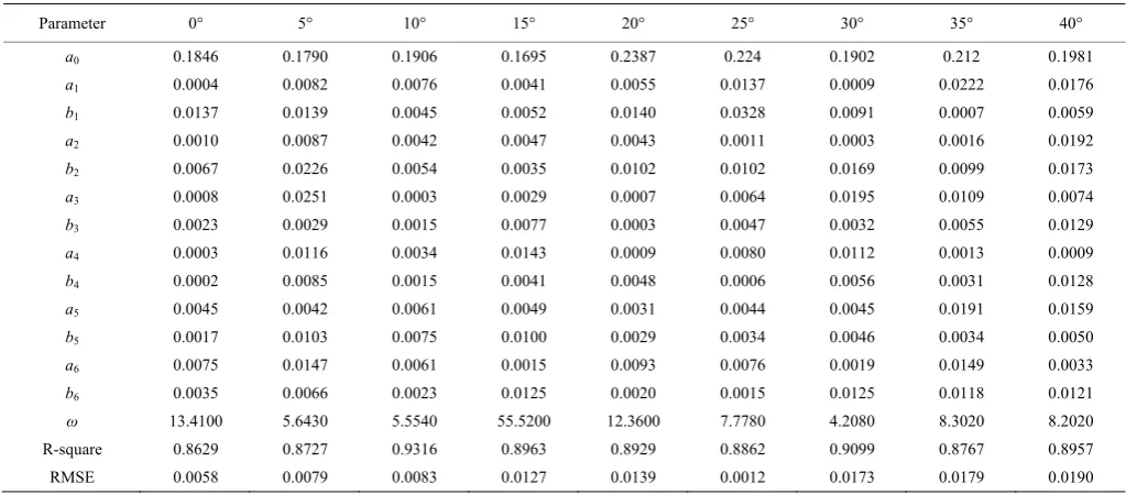
In this study, the data fitting operation was carried out via MATLAB. The trajectories of the head centroid movement were drawn when the goat walks on different slopes (Figure 8). The
parameters of the fitting equation of the head centroid motion of the goat are shown in Table 2.
Table 2 Goat head centroid motion fitting equation parameters
Parameter 0° 5° 10° 15° 20° 25° 30° 35° 40°
a0 0.1846 0.1790 0.1906 0.1695 0.2387 0.224 0.1902 0.212 0.1981
a1 0.0004 0.0082 0.0076 0.0041 0.0055 0.0137 0.0009 0.0222 0.0176
b1 0.0137 0.0139 0.0045 0.0052 0.0140 0.0328 0.0091 0.0007 0.0059
a2 0.0010 0.0087 0.0042 0.0047 0.0043 0.0011 0.0003 0.0016 0.0192
b2 0.0067 0.0226 0.0054 0.0035 0.0102 0.0102 0.0169 0.0099 0.0173
a3 0.0008 0.0251 0.0003 0.0029 0.0007 0.0064 0.0195 0.0109 0.0074
b3 0.0023 0.0029 0.0015 0.0077 0.0003 0.0047 0.0032 0.0055 0.0129
a4 0.0003 0.0116 0.0034 0.0143 0.0009 0.0080 0.0112 0.0013 0.0009
b4 0.0002 0.0085 0.0015 0.0041 0.0048 0.0006 0.0056 0.0031 0.0128
a5 0.0045 0.0042 0.0061 0.0049 0.0031 0.0044 0.0045 0.0191 0.0159
b5 0.0017 0.0103 0.0075 0.0100 0.0029 0.0034 0.0046 0.0034 0.0050
a6 0.0075 0.0147 0.0061 0.0015 0.0093 0.0076 0.0019 0.0149 0.0033
b6 0.0035 0.0066 0.0023 0.0125 0.0020 0.0015 0.0125 0.0118 0.0121
ω 13.4100 5.6430 5.5540 55.5200 12.3600 7.7780 4.2080 8.3020 8.2020
R-square 0.8629 0.8727 0.9316 0.8963 0.8929 0.8862 0.9099 0.8767 0.8957 RMSE 0.0058 0.0079 0.0083 0.0127 0.0139 0.0012 0.0173 0.0179 0.0190
4 Results and discussion
When the slopes are 0°, 10°, and15°, the head centroid movement is mainly concentrated in the ellipse near the x axis, compared with other angles. The reason is that the slope is small. The head alone in the slope near the swing can facilitate the goat’s steady walking. The difference between the abscissa of the head center of mass is 0.03, and the difference of the ordinate is 0.08. When the slopes are 20° and 25°, the head centroid movement is mainly concentrated in the ellipse close to the x-axis part. The difference between the abscissa of the head center of mass is 0.08, and the difference of the ordinate is 0.08. When the slopes are 30°, 35°, and 40°, the movement of head center of mass relative to the other slope is concentrated in the ellipse near the y-axis part. This result is due to the increase in slope degree to a certain value. When the goat needs to lift its head high, swinging up and down from the slope can stabilize and balance the walking of the goat. At this point, the head abscissa extreme difference is 0.06 and the vertical axis of the difference is 0.10. When the slope increases to 20°, the volatility of the trajectory suddenly becomes large. The reason is that the goat needs to stabilize its balance by increasing the movement of the head. When the slope is increased to 30°, the head shows a violent pendulum-like movement, ytmin<0.
When the slopes are 0°, 10°, and 15°, compared with other angles, the movement of head center of mass presents small fluctuations. This result is due to the small slope. Swinging the head up and down alone can facilitate the stable walk of the goat. When the slopes are 20° and 25°, the head centroid movement is mainly concentrated away from the x-axis and the value of y is large. The difference of the ordinate of the head center of mass is 0.09. When the slopes are 30°, 35° and 40°, the movement of head center of mass relative to the other slope fluctuates. This fluctuation is due to the increase in slope degree to a certain value. The need to move the head up and down during the swing can facilitate the goat’s stable and balanced walking. The slope of the coordinates is 0.12. When the slope increases to 30°, the fluctuation of the trajectory suddenly becomes large because the
goat needs to stabilize its balance by increasing the movement of the head.
5 Conclusions
A slope test scheme is designed and established to study the head mass motion parameters of a goat on various slopes. The scheme comprises an automatic slope adjustment system that provides test slopes with 0°~40°angles and a high-speed camera system that records head and neck images of the goat’s movement. MATLAB and other software are used to calculate the focal center motion trajectory. This scheme aims to gain access to motion parameters as a basis for future study on the stability of four-legged walking mechanism and to provide conditions for its application.
(1) When the goat walks on different slopes, relative to the head and neck connection, the head of the center of the heart is used for the quarter oval movement. When the slope gradient gradually increases, xt increases first and then reduces and yt increases first and then reduces. When the slope is increased to 20°, the trajectory of the head fluctuates suddenly. This fluctuation is due to the need for the goat to achieve steady and balanced walking by increasing the movement of the head.
(2) When the goat walks on different slopes, relative to the body centroid, the head of the heart exhibits “down–up–down” back and forth fluctuations in the movement. A cycle of movement of the goat on a 30° slope is used as an example. High-speed photography indicates that the cycle of movement of the leg and head when the goat is walking is as follows: “right front leg lifted–head down–right front leg pedal–head up–left front leg lifted–head down–left front leg pedal–head up or left front leg lifted–head down–left front leg pedal–head up–right front leg lifted–head down–right front leg pedal–head up”. When the slope gradient gradually increases, the volatility gradually increases.
Acknowledgements
(2017GGJS062), Research and Development Project of Snake-like Robot Technology of Luoyang Power Supply Company of State Grid and the postdoctoral fund of Henan Province (2012086).
[References]
[1] Ren L Q, Liang Y H. Coupled BIOnics. Science Press, 2011. [2] Liu Z H, Shi C H, Kang S H, Li H Z, Huang L, Li C H, et al. Design and
obstacle analysis of a novel agricultural machinery walking mechanism. Journal of Agricultural Mechanization Research, 2014; 36(7): 220–224. (in Chinese)
[3] Gritl H, Khraief N, Belghith S. Period-three route to chaos induced by a cyclic-fold bifurcation in passive dynamic walking of a compass-gait biped robot. Communications in Nonlinear Science and Numerical Simulation, 2012; 17(11): 4356–4372.
[4] Arnold A S, Lee D V, Biewener A A. Modulation of joint moments and work in the goat hindlimb with locomotor speed and surface grade. Journal of Experimental Biology, 2013; 216(12): 2201–2212.
[5] Boye J K, Thomsen M H, Pfau T. Accuracy and precision of gait events derived from motion capture in horses during walk and trot. Journal of Biomechanics, 2014; 47(5): 1220–1224.
[6] Gillis G, Flynn J, Mcguigan P A. Patterns of strain and activation in the thigh muscles of goats across gaits duringlevel locomotion. Journal of Experimental Biology, 2005; 208(24): 599–611.
[7] Speck O, Speck D, Horn R, Gantner J, Sedlbauer K. Biomimetic bio-inspired biomorph sustainable? An attempt to classify and clarify biology-derived technical developments. Bioinspiration & Biomimetics, 2017; 12(1): 1–16.
[8] Ge W J. Imitation kangaroo jumping robot kinematics and dynamics research. Xi’an: Northwestern Polytechnical University, 2006. (in Chinese) [9] Ge W J, Shen Y W, Yang F. Research on the driving characteristics of
bionic kangaroo-hopping robot. Chinese Journal of Mechanical Engineering, 2006; 17(8): 857–861. (in Chinese)
[10] Ge W J, Shen Y W, Yang F. Hopping gait kinematics for bionic kangaroo-hopping robot. Journal of Mechanical Engineering, 2006; 42(5): 22–26.
[11] Gong J Q. Study on the effect of head - and - tail regulating device on the dynamic performance of four-legged. Beijing: Beijing Jiaotong University, 2015. (in Chinese)
[12] Zhang X L, Gong J Q, Liu H. SCS based simulation platform for quadruped bionic robots. Journal of Beijing Jiaotong University, 2015; 39(8): 23–28. (in Chinese)
[13] Tian X Q, Li J, Zhao G B, Ji C R. Application of center gravity adjusting
device on static walking of quadruped robot. Machine Design and Manufacturing Engineering, 2008; 37(23): 25–28. (in Chinese)
[14] Zhang F, Wang W, Zhang G Y, Wang J, Qiu Z M. Gait analysis of goat at different slopes and study on biomimetic walking mechanism. Int J Agric & Biol Eng, 2016; 9(3): 40–47.
[15] Zhang F, Wang W, Zhang G Y, Wang J, Qiu Z M. A gait analysis of goat slope walking. Jiangsu Agricultural Sciences, 2017; 45(8): 196–199. [16] Briggs R, Lee J, Haberland M, Kim S. Tails in biomimetic design:
analysis simulation and experiment. IEEE/RSJ International Conference on Intelligent Robots & Systems, 2012; pp.1473–1480.
[17] Pang H H, Ge W J, Yang F. Locomotion analysis of hopping kangaroo robot considing tail. Machine Tool & Hydraulics, 2007; 35(8): 1–4. [18] Curt W, Charles J V J, Louis A. Ritz balance in the cat: role of the tail
and effects of sacrocaudaltransection. Behavioural Brain Research, 1998; 91(1-2): 41–47.
[19] Zhang F, Zheng L M, Wang W, Wang Y F, Wang J J. Development of agricultural bionic mechanisms: investigation of the effect of joint angle and pressure on the stability of goats moving on sloping lands. Int J Agric & Biol Eng, 2018; 11(3): 35–41.
[20] Wada N., Hori H, Tokuriki M. Electromyographic and kine-matic studies of tail movements in dogs during treadmill loco-motion. Journal of Morphology, 1993; 217(1): 105–113.
[21] Oeffner J, Lauder G V. The hydrodynamic function of shark skin and two biomimetic applications. Journal of Experimental Biology, 2012; 215(5): 785–795.
[22] Pu X, Li G J, Huang H L. Preparation anti-biofouling and drag-reduction properties of a biomimetic shark skin surface. Biology Open, 2016; 5(4): 389–396.
[23] Ding L, Gao H B, Deng Z Q, Song J H, Liu Y Q, Liu G J, Iagnemma K. Foot-terrain interaction mechanics for legged robots: Modeling and experimental validation. International Journal of Robotics Research, 2013; 32(13): 1585–1606.
[24] Shill J J, Collin E G, Coyle E, Clark J. Terrain identification on a one-legged hopping robot using high-resolution pressure images. IEEE International Conference on Robotics & Automation, 2014; pp.4723–4728. [25] Gu G Y, Zhu J, Zhu L M, Zhu X. A survey on dielectric elastomer
actuators for soft robots. Bioinspiration & Biomimetics, 2017; 12(1): 1–22. [26] Wang W, Li X P, Wu S L, Zu P H, Zhao F. Effects of pendular waist on
gecko’s climbing: Dynamic gait analytical model and bio-inspired robot. Journal of Bionic Engineering, 2017; 14(2): 191–201.