Bread-slicing machine
Kolawole A. Oladejo
1, Kehinde A. Taiwo
2, Dare A. Adetan
1,
and Afolabi T. Morakinyo
2*(1. Department of Mechanical Engineering, Obafemi Awolowo University, Ile-Ife, Nigeria; 2. Department of Food Science and Technology, Obafemi Awolowo University, lle-Ife, Nigeria)
Abstract: This study developed a compact front loading machine for slicing loaves of bread. The machine is fast, efficient, safe and easy to operate. It was designed to accommodate a normal loaf of bread per pass. It works on the principle of gravity loaf in-feed system and the up-and-down reciprocating motion of the blade frame that carries 22 parallel cutting blades spaced at a regular interval of 14.5 mm apart. It is driven by a 2 horsepower electric motor via a V-belt power transmission system. The moving components are born on self-lubricating bearings and specially designed vibration absorbers; it automatically stops to save running cost once the loaf is completely sliced. It also incorporates a crumb collection tray to enhance the hygiene of the process. Evaluation tests revealed that increasing the cutting speed above the standard commercial bakery speed of 420 r/min increased bread wastage and reduced uniformity of slice thickness.
Keywords: bread slicing, sliced-bread, slicing machine, reciprocating blades
Citation: Kolawole A. Oladejo, Kehinde A. Taiwo, Dare A. Adetan, and Afolabi T. Morakinyo. 2016. Bread-slicing machine. Agricultural Engineering International: CIGR Journal, 18 (2):209-218.
1 Introduction
1Bread is a staple food around the world that is
prepared by baking dough of flour and water. It may be
leavened or unleavened. Salt, fat and a leavening agent
such as yeast are common ingredients; it may contain a
range of other ingredients such as milk, egg, sugar, spice,
fruit, vegetables, nuts or seeds. Adejugbe et al. (2012)
reported that bread has become a common food and a
cheap source of carbohydrate to all and sundry among
Nigerians. Bread slicing prevents wastage, allows for
even sharing, packaging for convenience and increased
market value of the bread. However, the problem of
sanitation during the slicing process (and indeed other
bread production operations) has become a source of
concern to stakeholders. A machine that will ensure that
there is little or no human contact during this slicing
operation is therefore a welcome development. Several
approaches have been made in the past to produce a
Received date: 2015-08-20 Accepted date: 2016-02-18
*Corresponding author: Afolabi T. Morakinyo, Department of Food Science and Technology, Obafemi Awolowo University, lle-lfe, Nigeria. Email: [email protected].
simple, efficient and reliable bread slicing device with
varying degrees of achievement. The ability to provide
adequate support for the bread loaf and guidance of the
slicing knife requires a great attention.
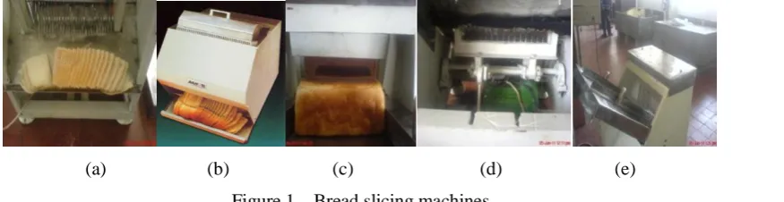
Earlier studies on the improvement of bread-slicing
machines have been reported (Adio and Oluwole, 2008;
Tunji and Joba, 2008). Some models of existing bread
slicing machines are shown in Figure 1. A bread-slicing
machine makes it easier to slice bread without going
through much stresses. It also helps to prevent wastage;
allows for even sharing; packaging for convenience and
increase market value of the sliced bread. The system
consists of a relatively simple, efficient and reliable
mechanism designed to reduce cost, decrease down-time,
increase efficiency, improve alignments, achieve
effective slicing and prevent the blade from deformation
during operation.
Olatunji and Olowojoba (2008), Odior et al. (2009)
and Oladejo et al. (2015) developed various models of a
bread slicing machine that utilized a power screw to feed
the bread loaf towards the reciprocating slicing blade and
machines are expensive due to incorporation of additional
electric motor to drive the power screw; however, their
major shortcoming is that the shaft power output is
insufficient to cause the desired reciprocating action of
the blade frame.
In order to realize the multi-functioning capacity
objective of an existing slicing and shredding machine,
which is a kind of food processing machinery widely
used in the food processing industry, Zhang et al. (2013)
modified and improved the machine by incorporating a
gear and clutch drive system. Odior (2012), in an
attempt to facilitate the processing of meat, developed a
meat slicing machine which consists of a cutting blade, a
meat feeder, a meat tray, a meat clamp, the crank
mechanism and a control unit. The machine was
designed to enhance the hygienic slicing of meat for both
domestic and commercial consumption and it can
accommodate from one to six cutting blades which are
spaced 6.5 mm from each other to give a meat slice
thickness of 5 mm per slice. It takes an average of four
seconds to cut a slice and one hour for 2.673 tonnes of
meat. Odior (2007) reported the development of a bread
slicing machine using mainly some locally sourced
materials; and it can accommodate a normal loaf of bread
per pass. The machine is designed to accommodate
twenty cutting blades which are spaced 14.5 mm from
each other to give a bread slice thickness of 13 mm per
slice. It takes an average of five seconds to slice a loaf
of bread.
Bindon and Thomas (1995) reported bread slicing
guide appliance that supports and holds bread loaves of
varying sizes while providing and alignment to the slicing
knife; it incorporates an electric fan that facilitates debris
collection by aspiration. Birmingham (1978) designed a
bread slicer which accommodates loaf variability by
provision of several grooves in the base plate that
provided alternate position for the slicing guides. Also,
no lateral holding force could be applied to the loaf
during slicing as a result of loaf variability. In
Hayman-Bread Slicer, the slicing guides were inserted in
a series of grooves, thus allowing for a variable loaf size,
as an end stop and side pressure clamping were not
included; so the loaf is placed in position without
standardization during slicing (Wenske, 2003). Kehinde
(2002) designed and fabricated a bread slicer using local
materials for affordability, but the slicer can only slice a
particular length of loaf because the guide is fixed instead
of being adjustable. Bayo (2006) and Abu et al. (2014)
attempted to improve on the design by using a variable
speed motor and making use of adjustable guide. The
objective of this study is to develop a bread slicer with
adjustable guides to enhance loaf alignment and produce
an effective slicing operation with high efficiency.
2 Materials and method
2.1 Operational principle
The bread slicing machine makes use of a
reciprocating motion derived from an electric motor
through a slider-crank drive mechanism and gravity
in-feed system. The machine consists of a set of parallel
blades that is vertically arranged and mounted on a blade
frame. The ends of the blades are secured to the blade
frame with the help of fasteners M 6 × 5 mm (bolts and (a) (b) (c) (d) (e)
nuts). The blade frame is attached to the reciprocating
drive mechanism which drives it up and down within a
frame guide to create the cutting action on a loaf of bread.
The loaf is fed in through the gravity in-feed system in
the absence of a pushing plate, while the crumbs are
collected through the crumb tray.
2.2 Design and strength calculation:
2.2.1 Selection of the drive motor
A single phase, 2 horsepower electric motor was
used to power the blade frame. The motor runs at 1500
r/min (angular velocity (N1), according to manufacturer’s
specifications). The selection involved the
determination of the power required to drive the blade
frame and the blade. It is desired to have 14 up and
down (reciprocating) motions per second (r/sec), thus the
required angular velocity, N2, of the crank driving the
connecting rod plus blade assembly was calculated as
follows (Olatunji and Oluwajoba, 2008; Oladejo and
Oriolowo, 2015):
N1 = 1500 r/min
sec
/
2
14
2
r
N
(1)Converting, N2in r/sec to N2 in r/min
min
/
420
min
1
60
sec
/
7
2r
s
r
N
(2)The weight of the connecting rod plus blade
assembly (blade frame and the included blades), Wt, is
calculated as: 81 . 9 )} 2 ( ) 8 ( ) ( ) 4 {(
f f b b b c c
t A f l b f t b l A f
W
N
5
.
14
For a sprocket radius of 0.25 m, the linear velocity,
V, of the crank pin on the sprocket that lifts the
connecting rod plus blade assembly is given by
s
m
V
11
/
60
420
25
.
0
2
(3)Power (P) required to lift the connecting rod plus
blade assembly is given as
P = Wt x V = 14.5 x 11 = 160 W
Applying factor of safety of 6 (Khurmi and Gupta,
2005), the required drive power = 6 × 160 = 960 W.
Since 750 W = 1 hp, a 2 horsepower drive motor is
recommended.
2.2.2 Selection of V-Belt
Belts are employed to transmit power from one shaft
to another where it is not necessary to maintain an exact
speed ratio between two shafts. Power losses due to slip
and creep amount to from 3% to 5% for most belt drives
(Bindon and Thomas, 1995):
When the belt is rotating, there is always a tight side
which sustains a tension, T1, and a slack side which
sustains tension, T2, such that.
P = (T1 – T2) × V (4)
Taking into account the centrifugal effects of the
mass of belt (M) in motion, the relationship of the forces
is given as:
) 2 ( 2 2 2 1 Sin
e
MV
T
MV
T
(5)Where β = angle of wrap of pulley around the smaller pulley and α = included V-angle of the driving
V-pulley.
The average tension in the belt is given as:
2
/
)
(
1 2 0T
T
T
(6)Selection of V-belt and pulleys in the design of the
bread slicer was accomplished with the use of a
manufacturer’s catalogue (Fenner Power Transmission
Catalogue). The basic variables required for the
selection are transmission power, P, motor speed, centre
distance and pulley diameter.
The length of the belt is calculated using the
following Equation (7).
C
C
d
D
d
D
L
[
(
)
/
2
]
[(
)
2/
4
]
2
(7)Substituting the diameters of the big and small
pulleys (20 cm and 9.5 cm respectively), and the centre
L = ( (0.2 + 0.095)/2) + ((0.2 – 0.095)2/4 × 0.7) + 2 ×
0.7 = 1.867 m
A49 section belt was used for the transmission of
power.
2.2.3 Shaft design
This primarily consists of the determination of the
correct shaft diameter in order to ensure satisfactory
strength and rigidity when the shaft is transmitting power
under various operating and load conditions (Hall et al.,
1980; Adetan et al., 2013). The shaft is made of ductile
iron material.
(a) Torsional Moment (Mt):
t
M
was calculated using:R
T
T
M
t(max)
(
1
2)
(8)ASME code equation for a hollow shaft was
employed to determine shaft diameter.
2 2
3
)
(
)
(
16
t t b
b s
M
K
M
K
S
d
(9)Based on this equation (9), 20 mm shaft diameter
was recommended.
(b) Torsional rigidity
Torsional rigidity is based on the permissible angle
of twist. The amount of permissible twist depends on
the particular application and varies about 0.3 deg/m for
machine to shafts to about 3 deg/m for line shafting
(Petersen et al., 1996):
4
584
Gd
L
M
t
; for a solid circular shaft.(10)
Using the maximum permissible amount of twist of
3 deg/m for line shafting, the minimum diameter was
obtained as d = 14 mm. Since this is less than the
diameter of 20 mm earlier determined using equation (9),
a 20 mm diameter solid shaft was chosen.
2.2.4 Keys design
Keys are employed to prevent relative motion
between the shaft and the connected member (sprocket,
pulley) through which torque was transmitted. A
rectangular sunk key with head at one end (Gib-head key)
was used because of the easy of removal (Bayo, 2006;
Oladejo and Oriolowo, 2015). The usual dimensions
(width, wk, and thickness, tk) of the gib-head key are
obtained as:
Width of key, wk = d/4 (11)
Thickness of key,
6
3
2
w
d
t
kk
(12)Using a shaft diameter, d, of 20 mm, from Equations
(10) and (11), we obtain wk = 5 mm and tk = 3.33 mm.
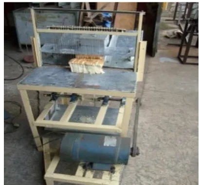
2.3 Description of the Machine working components.
The bread slicing machine (gravity feed bread slicer)
is shown in Figure 2. The dimension of the complete
assembly of the machine is 600 mm × 500 mm × 1000
mm. It consist of a fixed frame and a reciprocating
blade frame, crankshaft, driven shaft, crank wheel,
connecting bars, in-feed and out-feed crumbs trays,
keys, pulleys, plummer bearings, bolts and nuts,
blade holder and blades.
2.3.1 Frames
The fixed frame is made of a 5 mm thick mild steel
square pipe of cross-sectional dimension 40 mm × 40 mm.
It is welded together to form a cuboidal structure of
dimension 600 mm × 600 mm × 700 mm, having four
stands suspended on dampers. The base plate of the
electric motor is mounted at a vertical height of 200 mm,
while the crankshaft is suspended at another vertical
height of 400 mm on the fixed frame. The driven shaft
transfers motion from the connecting bar to the two
reciprocating frames of 400 mm × 200 mm, where blades
were mounted as shown in Figure. 2.
2.3.2 Crankshaft
This is made of mild steel material of Ɵ 20 × 450
mm, as a driving shaft, driven by the electric motor
through V-belt drive arrangement at one end. At the
other end is mounted the crank wheel of 220 mm
diameter, with the help of key-way of 6 mm × 5 mm × 30
mm. The crankshaft is positioned on the machine frame
connecting rod is located at a distance of 50 mm out of
the center of the crank wheel to facilitate the
reciprocating motion of the blade mechanism.
2.3.3 Connecting bars
These are made of mild steel material of rectangular
bars of 50 × 150 × 8 mm. They are two in number,
bolted together with the help of the gudgeon pins and
sleeves to facilitate frictionless reciprocating motion.
The first connecting bar is connected to the crank wheel
while the second bar is connected to the driven shaft of
the blade mechanism. The connecting bars convert the
rotary motion of the crankshaft to the reciprocating
motion of the blade frame as shown in Figure 2.
2.3.4 Keys
It was a rectangular sunk key with a head at one end
(gib-head key) was employed. The key material was
made from AISI 1020 cold-drawn steel of 6 mm × 5 mm
×30 mm.
2.3.5 Blades
The slicer blades are made of AISI 410 stainless
steel material of 15 mm thickness, having serrated teeth;
each blade is 15 mm wide and 250 mm long. They are
independently mounted on the blade holder using
fasteners of M 6 × 5 mm (bolts and nuts) to enhance
replacement, and positioned at a gap of 14.5 mm to each
other.
2.3.6 In-feed, out-feed and crumbs tray
They are made of AISI 410 Stainless Steel material
of 2.5 mm thickness in order to eliminate corrosion, rust
and wear and therefore prevent food contamination.
2.3.7 Bolts and nuts
They were generally used to fasten the components
described above together to enhance ease of
disassembling and replacement of faulty parts.
2.3.8 Damper
A damper of rectangular shape of 100 mm × 100
mm × 30 mm was employed at the base of each stand in
order to reduce noise and vibration during slicing
operation.
Figure 2 Assembling of the bread slicer
3 Results and discussion
3.1 Testing and evaluation
3.1.1 Testing procedure
The performance evaluation of the bread slicer was
based on the value of the overall efficiency of the slicer
which is a function of loaves cutting ability, loss in
weight of loaves and slice uniformity. The performance
of the bread slicer was evaluated by load testing it with
170 mm (length) × 67 mm (breadth) × 80 mm (height)
loaves (Specimen A) and 250 mm × 75 mm × 105 mm
loaves (Specimen B). The results of the tests are shown
in Tables 1, 2 and 3 below.
3.1.2 Time of cutting
The bread slicer was operated and the time taken for
it to slice samples of Specimen A (170 mm × 67 mm × 80
mm loaves) and Specimen B (250 mm × 75 × 105 mm
loaves) were obtained. The average cutting time was
evaluated using the equation below:
n
(13)3.1.3 Weight loss
Weight loss was obtained by weighing the crumbs of
samples on the weighing balance or alternatively by
weighing samples of each specimen before slicing and
weighing after slicing. These helped to evaluate the
1
100
,
,
,
B
A
W
B
A
W
B
A
W
PWL
bs as bs (%) (14)
A
B
W
bs,
= Weight before slicing loaves ofSpecimen A or B, kg,
A
B
W
as,
= Weight after slicing loaves ofSpecimen A or B, kg
3.1.4 Slicing uniformity
The thickness of each slice of specimens A and B
were measured at the end of the slicing operation and the
number of slices that did not conform to standard
thickness (10 mm) was determined. Obtaining slicing
uniformity helped to analyze for the conformity with
respect to standard thickness for every 24 slices obtained
from samples of both specimens. The equation for
evaluating the percentage conformity (PCTS) to standard
thickness is given as:
,
100
,
B
A
N
B
A
N
PC
T cTS (%)
(15)
The equation for evaluating the percentage that
doesn’t conform to standard thickness (PCNS) is given as:
100
,
,
B
A
N
B
A
N
PC
T dc NS (%) (16)During load testing, the slicer was operated at the
speed of 450 r/min as for a standard commercial bakery,
in-feed weight of 2.8 kg and at an in-feed angle of 57o.
The values obtained for the above load testing are
recorded in Tables 1 and 2.
3.2 Efficiency of the bread slicer
The efficiency of the machine, η(A,B), was calculated
based on PWL(A,B) of both specimens (A and B) using the
following equations:
AB
B
A, ) PWL ,
( 100
(17)3.3 Overall efficiency of the bread slicer
The overall efficiency of the machine was calculated
based on the efficiencies, ηA and ηB, obtained using
equation (17) for both specimens (A and B). Thus, the
formula for evaluating bread slicer overall efficiency, ηBS,
is given as:
2
B A BS
(18)2
63
.
89
8
.
89
BS
= 89.715 %Hence, with respect to calculated percentage loss in
weight the bread slicer overall efficiency,
715
.
89
BS
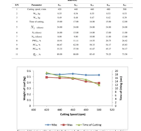
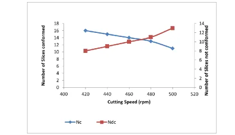
%.3.4 Performance of the bread slicer at different speeds
The bread slicer tested at cutting speeds varying
between 420 and 500 r/min (Figures 3, 4 and 5) with a
fixed in-feed weight of 2.8 kg, and an in-feed tray angle
of 57o. The test was carried out on 250 mm × 75 mm ×
105 mm loaves (Specimen C). The purpose of the
performance test was to determine the relationship
between the speed (an independent variable) and the
efficiency of the bread slicer for an effective slicing
operation.
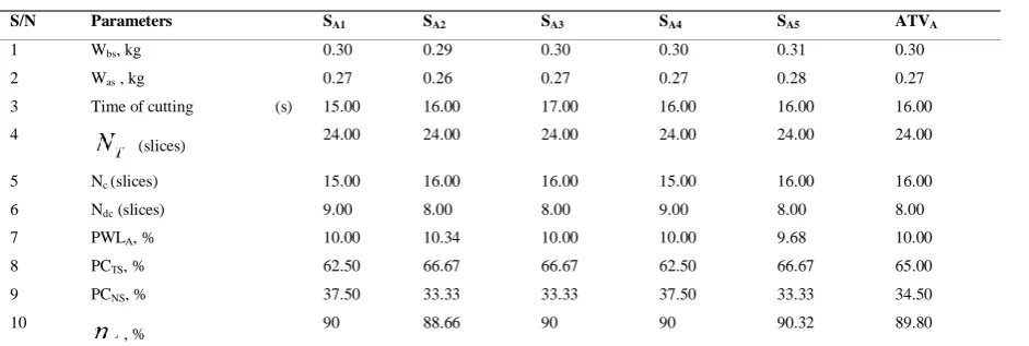
Table 1 Results of load testing of specimen A (170 × 67 × 80 mm of Loaves)
S/N Parameters SA1 SA2 SA3 SA4 SA5 ATVA
1 Wbs, kg 0.30 0.29 0.30 0.30 0.31 0.30
2 Was , kg 0.27 0.26 0.27 0.27 0.28 0.27
3 Time of cutting (s) 15.00 16.00 17.00 16.00 16.00 16.00 4
(slices) 24.00 24.00 24.00 24.00 24.00 24.00 5 Nc (slices) 15.00 16.00 16.00 15.00 16.00 16.00
6 Ndc (slices) 9.00 8.00 8.00 9.00 8.00 8.00
7 PWLA, % 10.00 10.34 10.00 10.00 9.68 10.00
8 PCTS, % 62.50 66.67 66.67 62.50 66.67 65.00
9 PCNS, % 37.50 33.33 33.33 37.50 33.33 34.50
10
Table 2 Results of load testing of specimen B (250 × 75 × 105 mm of loaves)
S/N Parameter SB1 SB2 SB3 SB4 SB5 ATVA
1 Wbs, kg 0.55 0.53 0.53 0.54 0.55 0.540
2 Was, kg 0.49 0.48 0.47 0.49 0.49 0.484
3 Time of cutting, s 19.00 20.00 22.00 19.00 20.00 20.000 4 (slices) 24.00 24.00 24.00 24.00 24.00 24.00 5 Nc(slices) 15.00 16.00 16.00 16.00 15.00 16.000
6 Ndc (slices) 9.00 8.00 8.00 8.00 9.00 8.000
7 PWLB, % 10.91 9.43 11.32 9.26 10.91 10.370
8 PCTS, % 62.50 66.67 66.67 66.67 62.50 65.00
9 PCNS, % 37.50 33.33 33.33 33.33 37.50 35.00
10 , % 89.09 90.57 88.68 90.74 89.09 89.63
Table 3 Performance of bread slicer at different cutting speeds using specimen C (250 × 75 × 105 mm of
loaves)
S/N Parameter SC1 SC2 SC3 SC4 SC5
1 Cutting speed, r/min 420 440 460 480 500 2 Wbs, kg 0.55 0.54 0.55 0.53 0.53
3 Was, kg 0.49 0.48 0.47 0.42 0.39
4 Time of cutting, 19.00 17.00 16.00 15.00 12.00 5 (slices) 24.00 24.00 24.00 24.00 24.00 6 Nc (slices) 16.00 15.00 14.00 13.00 11.00
7 Ndc (slices) 8.00 9.00 10.00 11.00 13.00
8 PWLC, % 10.91 11.11 14.55 20.75 26.42
9 PCTS, % 66.67 62.50 58.33 54.17 45.83
10 PCNS, % 33.33 37.50 41.67 45.17 54.17
11 , % 89.09 88.89 85.45 79.25 73.58
3.5 Evaluation of the bread slicer
The results revealed that PWLC and PCNS increased,
while PCTS and η (overall bread slicer efficiency)
decreased with increase in cutting speed above the
standard speed (420 r/min) as shown in Table 3. A
reduction in the bread slicer efficiency may lead to early
slicing equipment down time, losses in the slicing blade
tension, parts deformation (blade frame), increased noise,
increased vibration, misalignment and high cost of
maintenance. The lower cutting speed leads to a better
penetration rate, longer life of blades, increased load
slicing time, reduced heat build-up, minimal blade
breakage and smoother slices.
4 Conclusions
The development of the bread slicing machine in
this study involved the design and fabrication of some
principal components which include the cutting blades
(22 set), blade frame, in-feed and out-feed tray, crumbs Figure 4 Variation of percentage conformity with standards and percentage weight loss at different cutting speeds
tray, in-feed weight, and the drive mechanism.
Considering the results of the performance test, it was
observed that the machine will best serve the purpose of
slicing operation at reduced vibration, minimum noise
generation, reduced cost and clean slicing environment
with optimum efficiency as very smooth slices were
obtained when run at the standard speed of 420 r/min.
The gravity in-feed tray, out-feed tray and crumbs tray
could be motorized so that the bread slicer will be fully
automatically operated to reduce the stress imposed on
the operator. Government should encourage the mass
production of satisfactorily efficient locally made bread
slicers such as the one reported in this article because
they are cost effective compared to imported bread
slicers.
Acknowledgement
The authors acknowledge the support of the
Department of Mechanical Engineering and the
Department of Food Science and Technology, OAU,
lle-lfe, Nigeria.
References
Abu, R., K. A. Oladejo, and U. O. Adekanmbi. 2014. Development of a model for the beam analysis, International Conference of Mechanical Engineering, Energy Technology and Management, (IMEETMCon), 3rd – 5th September, pp. 562–578, Nigeria.
Adejugbe, I. T., O. K. Ukoba, and O. R. Medupin. 2012. Development of a low cost bread slicing machine,
International Journal of Science and Technology, (IJST), 2(9):622-630.
Adetan, D. A., L. O. Adekoya, and K. A. Oladejo. 2007. An improved pole-and knife method of harvesting oil palm. Agricultural Engineering International: the CIGR journal, Manuscript PM 06027, 9:1-11.
Adetan, D. A., K. A. Oladejo, and S. K. Fasogbon. 2008. Redesigning the local manual automobile tyre bread beaker. Technology in Society, 30: 184-193.
Adetan, D. A., G. Agwogie, and K. A. Oladejo. 2013. Assessment of the problem of manual automobile tyre bead breaking equipment in Nigeria. Nigerian Journal of Technology, (NIJOTECH), 32(3): 485-491.
Adio, O. I., and S. I. Oluwole. 2008. Improvement on the development of a bread-slicing machine, Unpublished
B.Sc Thesis, Department of Mechanical Engineering, Obafemi Awolowo University, Ile-Ife. Nigeria.
Anderson, K., and A. Ohlsson. 1999. Life cycle assessment of bread produced on different scales. International Journal of Life Cycle Assessment, 4(1): 25-40.
Bayo, S. L. 2006. Design and construction of a bread slicing machine, Unpublished B. Tech Thesis, Department of Food Science and Engineering, Ladoke Akintola University of Technology, Ogbomosho.
Bindon, J. N., and P. R. Thomas. 1995. Collapsible bread slicing appliance with electric fan. US Patent
No.:5,440,959 of August 1995.
www.google.com/patent/US5440959, accessed August 2015.
Hall, A. A, A. R. Hollowenko, and H. G. Laughen. 1980. Theory and problems of machine design, McGraw-Hill Book Company, New York, 3. 113-140.
Kehinde, O. G. 2002. Design and construction of a bread slicing machine, Unpublished B. Tech Thesis, Department of Food Science and Engineering, Ladoke Akintola University of Technology, Ogbomosho.
Khurmi, R. S., and J. K. Gupta. 2005. Machine Design. First Multicolor Revised Edition 2005. Publisher; Eurasia Publishing House (PVT) ltd. New Delhi, India 101-102. Odior, A. O. 2012. Development of a meat slicing machine
using locally sourced materials. International Journal of Engineering and Technology(IJET), 2(2):202-208. Odior, A. O. 2007. Development of a bread slicing machine
from locally sourced materials. Journal of Technology and Education in Nigeria, 12(2):62-67.
Odior, A. O., F. A. Oyawale, and E. S. Orsarh. 2009. Development of a vegetable slicing machine from locally sourced materials. The Journal of the Nigerian Institution of Production Engineers, 11(1):143-156. Oladejo, K. A., and K. T. Oriolowo. 2015. Analysis of gear
milling at various speeds, time and feed rates. Nigerian Journal of Technology, (NIJOTECH), 34 (1): 150-155. Olatunji, B. O., and P. A. Olowojoba. 2008. Design and
fabrication of a bread slicer, Unpublished B.Sc Thesis, Department of Mechanical Engineering, Obafemi Awolowo University, Ile-Ife, Nigeria.
Petersen, B. L., A. M. Ledford, and G. L. Kruse. 1996. Variable thickness bread slicer. Official Gazette of the United States Patent and Trademark Office. Patents 1179(5):2906, 31.
Wenske, P. O. 2003. History of sliced bread little known on 75th anniversary. Kansas City Star,
29th July, 2003.
Zhang, G. L., H. Yang, S. P. Pan, J. F. Mo, and F. Jiao. 2013.
The improvement and development of slicing and shredding machine function. Applied Mechanics and Materials, 394: 591-596.
Nomenclature
AISI American Iron and Steel Institute ASME America Society of Mechanical Engineer CAD Computer Aided Design Density of frame, kg/m3
CIM Computer Integrate Manufacture Blade length, mm
Cross sectional area of the frame, m2 Blade width, mm Cross sectional area of connecting rod,m2 Crank Diameter, mm
Width of frame, mm Length of frame, mm
Density of connecting rod, kg/m3 Angular velocity of the reduced speed, rpm
Density of the blade material, kg/m3 Bread Slicer Efficiency with Respect to Samples of Specimen C,
Number of slices that conform to standard thickness Bread Slicer Efficiency with Respect to Samples of Specimen B,
Ndc (A) Number of slices that do not conform to standard
thickness Bread Slicer Efficiency with respect to Samples of Specimen A
Average time taken, s, Combined shock and fatigue factor Applied to torsional moment-1.0
Blade thickness, mm Combined shock and fatigue factor Applied to bending moment-1.5
Weight before slicing loaves of Specimen B, kg Weight after slicing loaves of Specimen A,
Weight after slicing loaves of Specimen B, kg Weight before slicing loaves of Specimen A, kg
Angle of twist, deg, Sum of time taken
SA5 Samples of Specimen A ATVA Average Total Value of Specimen A
Torsional modulus of elasticity for steel, GN/m2, PCTS (%) Percentage Conformity (PCTS) to standard thickness (10mm)
ATVB Average Total Value of Specimen B PCNS(%) Percentage that doesn’t Conform (PCTS) to standard thickness (10mm)
PWLC (%) Percentage Weight Loss with respect to Samples of Specimen C Shaft diameter, mm