Iranian Journal of Electrical & Electronic Engineering, Vol. 14, No. 1, March 2018 28
An Improved Control Method Based on Modified Delta-Sigma
Modulator for Buck Converter
M. Abarzadeh*(C.A.), F. Eshaghi* and E. Najafi Aghdam*
Abstract: This paper proposes an improved control method based on modified Delta-Sigma Modulator (DSM) to enhance transient response and improve harmonic contents of buck DC-DC converter. The main advantages of the proposed method are improving the output voltage frequency spectrum, correction of the output voltage harmonic contents and sideband harmonics, reduction of switching noise peaks at the output voltage, operating buck converter in continuous current mode independent of load current, significant reduction of inductor current ripple, improving the transient response of buck converter and correction of the input current harmonics. This progress is achieved by applying improved control method based on proposed forgetting function to enhance transient response of buck converter and also by using modified DSM to improve harmonic spectrum of the output voltage and reduce inductor current ripples. The simulation results confirm performance and feasibility of the proposed system.
Keywords: Buck Converter, Delta-Sigma Modulation, Forgetting Function, Switching Noise Reduction.
1 Introduction1
C-DC converters are widely used in renewable energy conversion systems (RECS), maximum power point tracking (MPPT) controllers and battery chargers to regulate variable input voltage to desired reference dc output voltage [1-4]. The regulation is normally achieved by pulse width modulation (PWM) at a fixed frequency and the switching device is normally IGBT or MOSFET. The buck DC-DC converter provides the output voltage lower than input dc voltage with the same polarity of input dc voltage [1].
Most of power converters are controlled by PWM strategy which is based on comparison between the reference signal and the periodic saw-tooth wave carrier signal in every carrier period. Consequently, large switching noise component for each multiple of the
Iranian Journal of Electrical & Electronic Engineering, 2018. Paper first received 31 August 2017 and accepted 20 February 2018. * The authors are with the Renewable Energy and Advanced Power Electronics Research Center, Sahand University of Technology, Tabriz, Iran.
E-mails: [email protected], [email protected] and
Corresponding Author: M. Abarzadeh.
carrier frequency appears [1,3,5]. Moreover, this switching process produce considerable sideband harmonics over a wide frequency range around the multiple carrier-frequency clusters [1,4]. These undesirable harmonic clusters cause serious malfunctions, such as acoustic noise, harmonic heating effects, mechanical vibration, switching losses in the semiconductor and electromagnetic interference (EMI) [5-7]. Hence, these drawbacks can be harmful in noise sensitive applications such as wireless communication systems and RF circuits [5-7]. By applying PWM method to switch-mode power converters, the output voltage has harmonic clusters around integer coefficients of switching frequency which causes abovementioned problems. In order to overcome these frailties, several switching methods such as random PWM (RPWM), first order delta-sigma modulation (DSM) [7-14], pulse frequency modulation (PFM) [15], hopping frequency modulation (HFM) [16,17] have been proposed for switch-mode power converters. The DSM method is one of the most promising approaches to suppress switching noise components and also sideband harmonics in comparison with the PWM strategy [5,14,18,19]. Because of spread spectrum feature of DSM, it can be used in high-frequency switch-mode converters [5,6,10,14,20]. However, this
D
Iranian Journal of Electrical & Electronic Engineering, Vol. 14, No. 1, March 2018 29
significant feature cannot realize when the DSM is applied to DC-DC converter [5]. The DSM method is based on the constant sampling interval of the switch-mode converter control [5]. Hence, the switching frequency can be varied under the constant sampling frequency which leads to harmonic-spreading specification of DSM [5,6,18,21-23]. In [24], a high-efficient low-noise buck converter with second order continuous-time DSM (CTDSM) and burst-mode techniques has been proposed. In order to achieve low output noise, low overshoot and undershoot voltage, and improve the recovery time, several techniques such as oversampling, noise shaping, burst mode, and continuous-time second-order DSM have been used in the proposed buck converter. In [25], a direct drive of a buck converter by DSM at 13.56-MHz sampling frequency without digital PWM has been presented. The output voltage of buck converter is directly controlled in the wide range by utilizing DSM at 13.56-MHz sampling frequency. In [26], a 10-μs transient recovery time and a low EMI DC–DC buck converter with a second-order DSM has been proposed. However, in DC-DC converters, due to the dc input, the first-order DSM has some harmonic spikes in output voltage. Therefore, a modified DSM method is proposed in this paper to eliminate these spikes and improve switching harmonic profile.
Buck DC-DC converter controlled by traditional PWM method operates in continuous current mode (CCM) or discontinuous current mode (DCM) based on the inductor current. It operates in either CCM when the inductor current does not fall to zero during converter operation or in DCM when the inductor current falls to zero [1,3]. In PWM method, duty cycle of PWM is changed by varying the load. Hence, by applying PWM method, buck converter operation mode depends on load value, switching frequency and inductor size. Therefore, depends on load, it may work in either CCM or DCM mode. Generally, in buck converter, it is better to operate in CCM even in presence of wide load variation. Hence, the modified control system based on combination of proposed DSM method and defined forgetting function is applied to buck converter. As a result, the proposed controller and modified DSM method have following improvements in buck converter performance
1.Switching noise peaks in output voltage are decreased significantly and harmonic profile is improved.
2.The buck converter always works in CCM mode in presence of wide load variation.
3.The transient response of buck converter output voltage is improved.
4.The current harmonic in converter input stage is modified.
This paper is organized as follows. In section 2, buck DC-DC converter is described. The delta-sigma modulation (DSM) is presented in section 3. The
proposed improved DSM method and modified controller are introduced in section 4. In section 5, the simulation results of proposed system are presented. Finally, conclusion is performed in section 6.
2 Buck DC-DC Converter
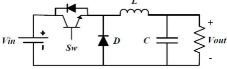
The buck DC-DC converter is depicted in Fig. 1. In buck converters, the output voltage is lower than the input voltage. Moreover, the output voltage is in same polarity with the input voltage and the negative line is common between the input and output. The L-C filter stores energy between the power switch on/off states. The inductor (L) current is controlled by power switch (Sw) duty cycle and diode (D) and the output voltage ripple is reduced by output capacitor (C). The L-C filter input voltage is the chopped input voltage by power switch duty cycle [1,3]. Hence, the buck converter output voltage can be defined as
(1) Duty cycle
out in
V V
In CCM, the state space averaging (SSA) method can be used to define state space model and transfer function of buck converter. Considering the average model of buck converter, the state space model of buck converter can be expressed as
(2)
( ) ( ) ( ) ( ) ( )
x t A x t Bu t
y t Cx t
where (3) ( ) ( ) ( ) ( ) ( ) ( ) ( ) ( ) C L in out C V t x t I t
u t V t
y t V t V t
The A, B and C matrices are expressed as
(4)
1 1 1 0 0 1 0 RC C A L B D L C Hence, the transfer function between output and input voltage of buck converter can be written as
Fig. 1 Buck DC-DC converter.
Iranian Journal of Electrical & Electronic Engineering, Vol. 14, No. 1, March 2018 30
(5)
2
( ) ( )
( ) 1
out
in
V s D
H s
L
V s LC s s
R
It can be considered that the state space model and transfer function of buck converter depends on the load variation. In addition, when the load current is small, the inductor current may fall to zero and the buck converter would work in DCM. Hence, the controller should be able to control the buck converter in wide range of load variation and in both CCM and DCM area [27].
3 Delta-Sigma Modulators
DSMs present the most efficient way of analog to digital converting in diverse range of signals and applications such as audio, sensor interfaces, biomedical and wireless communications. This versatility and simplicity in implementation have turned that as an attractive subject to researchers in different areas. In this study DSM is used as a part of controller block in the buck DC-DC converter to provide modified switching method. In comparison with PWM method which causes large switching noise and harmonic contents at the output voltage, employing DSM leads to low output noise, low overshoot and undershoot voltage, and improve the recovery time. The idea of using DSM is raised from capability of this modulator to shape the quantization noise introduced by digitizing the output 0 or 1 levels, whereas the other modulators do not have this capability. The principles behind the operation of DSMs are based on two important signal processing techniques, first oversampling which takes samples from input signal at higher rate than Nyquist rate (fN),
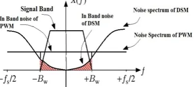
and second filtering the oversampled quantization error in a feedback manner to shape the noise power out of signal frequency band. Fig. 2 illustrates the general block diagram of a one bit DSM. It consists of a sample and hold block, loop filter of H(z) in discrete domain and a B-bit quantizer (1 bit in this study). Moreover noise frequency response of one bit DSM and PWM intended for conversion of low-pass signals is shown in Fig. 3. As depicted in Fig. 3, the noise frequency response of one bit DSM is significantly reduced and attenuated in band whereas the noise frequency of conventional PWM method is uniformly distributed in band.
The sample and hold block (S/H) samples the band limited input signal x(t) at a rate of sampling frequency (fs) and converts the analog input to discrete values in
time x(n). Finally, the x(n) is quantized by B-bit quantizer and generates discrete values in both time and domain. Based on the origination of the input signal, the gain of loop filter (H(z)) should be large within the signal band and small outside that. In this study the input signal is a low-pass signal and H(z) is a low-pass filter. The negative feedback operates in a way to cancel the differences between x(n) and y(n) in the signal band and filter the uniform noise of quantizer and push its power outside the desired band. The maximum power of
noise will occur at the half of the sampling frequency (fs). Accordingly, choosing fs high enough in S/H block,
will suppress the noise in the signal band and this can be easily filtered because of being far enough from the input signal.
Considering the switching speed restrictions in a DC-DC converter, fs can be increased for the purpose of
better signal to noise ratio (SNR). Besides that, multi-bit quantization and increasing the order of H(z) filter can more suppress the error noise in the frequency band. Because of using just one digital signal for switch controlling, the multi-bit quantization cannot be a relevant choice for maximizing SNR in this case. However, adding up the order of filter can efficiently improve SNR, while for orders more than 3 the probability of instability should be considered [28].
4 Proposed Modified Delta-Sigma Modulator and Improved Controller
The proposed control system of buck converter is shown in Fig. 4. As depicted in Fig. 4, there are three sub-systems in the proposed control system. Depicted sub-systems are explained as follows.
4.1 Sub-System1: Forgetting Function
Proposed f (Vref , VOut) defines accuracy and
convergence speed of output voltage during step change in reference or input voltage. In proposed control system, good tracking performance and improved transient response are desired. Hence, in sub-system 1, by applying f (Vref , VOut) as forgetting function to input
reference, transient response of buck converter is enhanced. In addition, in steady state condition, the tracking error between reference and output voltage is zero by tuning the proposed f (Vref , VOut). f (Vref , VOut) is
defined as follows
(6) ( , ) 1 ref Out
ref Out
ref
V V
f V V
V
Fig. 2 Block diagram of a one bit DSM.
Fig. 3 Noise frequency response of one bit DSM and PWM
over the signal band.
Iranian Journal of Electrical & Electronic Engineering, Vol. 14, No. 1, March 2018 31
Fig. 4 Proposed controller of DC-DC converter based on modified DSM and forgetting function.
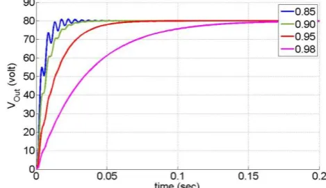
where 0< ξ <1 is a coefficient to define the speed and transient response performance of proposed controller. Generally, ξ has the value near to 1 to provide smooth transient response during converter start-up. The larger value of ξ results smooth and slower transient response whereas the smaller value of ξ results faster transient response with some oscillations. By applying zero order hold to the analogue modified reference value, the analogue value is converted to discrete value to use in modified discrete DSM.
4.2 Sub-System2: Unit Delay Feedback System
As shown in Fig. 4, in sub-system2, modified discretized reference value by f (Vref , VOut) and zero
order hold is applied to the system with unit delay feedback. g and g1 gains are used to tune the controller
to achieve desired reference voltage value. Therefore, in steady state condition, point x value can be expressed as
(7)
1
1 1
( )
( ) (1 )
ref ref
ref
x V g x V g
V g g x g
Considering x = KAmp × Vref , where KAmp is defined as
pre-amplification factor, and substitute in (7), it can be written as
(8)
1 1
1
(1 )
, Amp
Amp
g g K g
K g g
The KAmp, g and g1 values should satisfy the (8) criterion
to guaranty the zero tracking error in steady state conditions during various reference voltage values.
4.3 Sub-System3: First Order DSM
In this paper, the first order DSM as the last block of buck DC-DC converter controller has been implemented. Its input which is analog in domain and discrete in time, scaled down to 1 by the g2 coefficient and after passing through the modulator, its output is directly connected to the IGBT power switch gate. In this sub-system, H(z) can be utilized in first order DSM as a discrete time integrator or as a low pass filter with a pole at z = 1 by
(9) 1
( ) 1
H z z
The signal transfer function (STF(z)) between input and output of DSM and the quanization noise transfer function (qNTF(z)) between added noise of quantizer and output of DSM are defined to evaluate the noise shaping performance of DSM. The frequency characteristics of STF(z) and qNTF(z) can be defined by
(10)
1
1
1 / 1 ( )
1 1 / 1 1
( ) 1
1 1 / 1
z
STF z z
z
qNTF z z
z
With regards to abovementioned equations, the STF(z) is simply a delay and qNTF(z) is a high-pass filter for the purpose of pushing the in band noise to the out [29].
5 Simulation Results
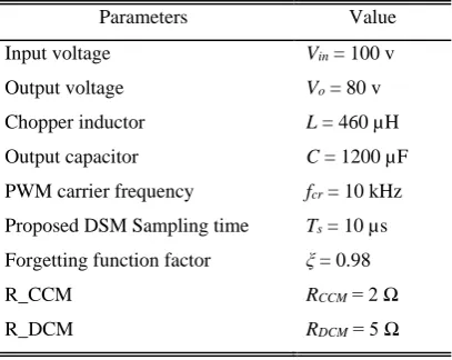
The buck DC-DC converter has been simulated in MATLAB/Simulink to evaluate the performance of the proposed control method. The simulated buck DC-DC converter parameters are presented in Table 1. In order to compare proposed DSM method with PWM method, both of these methods are implemented on buck DC-DC converter. In order to compare performance of the proposed DSM method with PWM method, carrier frequency of PWM is set to fcr = 10 kHz whereas the
DSM sampling time is set to Ts = 10 µs. Considering the
fact that the minimum duty cycle in PWM method is 10%, the sampling time of DSM method is set to
Table 1 Main parameters of DC-DC buck converter.
Parameters Value
Input voltage Vin = 100 v
Output voltage Vo = 80 v
Chopper inductor L = 460 µH Output capacitor C = 1200 µF PWM carrier frequency fcr = 10 kHz
Proposed DSM Sampling time Ts = 10 µs
Forgetting function factor ξ = 0.98
R_CCM RCCM = 2 Ω
R_DCM RDCM = 5 Ω
Iranian Journal of Electrical & Electronic Engineering, Vol. 14, No. 1, March 2018 32 1
10
10 10
s
T s
kHz
. Also, all the simulation
results are provided for ξ = 0.98 in defined forgetting function. Moreover, the simulation results are provided for PWM method with RCCM = 2 Ω and RDCM = 5 Ω
which result both CCM and DCM in PWM method. Then, the results are also presented for proposed control system based on modified DSM method for aforementioned loads.
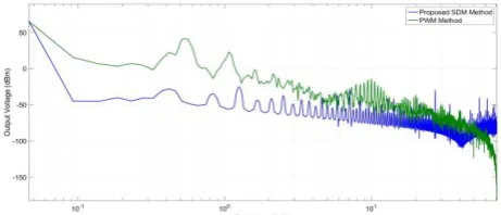
Figs. 5-9 present the simulation results of buck converter for PWM method in CCM and the proposed DSM method. The output voltage of buck converter during transient and steady state is shown in Fig. 5. As shown in Fig. 5, by applying the modified control method based on defined forgetting function and proposed DSM method, the transient response is smoother and also there is no ripple in output voltage in steady state. Figs. 6 and 7 depict the output voltage and its noise frequency response spectrums for PWM method and the proposed DSM method. It can be considered that by applying proposed DSM method, the output voltage spectrum is improved significantly. Moreover, not only is the harmonic cluster improved at lower frequencies, but also the switching harmonic clusters are reduced drastically. Fig. 8 presents the inductor current for PWM in CCM and the proposed DSM method. As depicted in Fig. 8, the inductor current ripple is decreased significantly in comparison with PWM method. This improvement is derived from inherent performance of delta-sigma modulation in the proposed DSM method which is based on sweeping the switching frequency. Hence, reduction in inductor current ripple leads to suppression the EMI noises and switching stress and losses. The buck converter input current is shown in Fig. 9 for PWM in CCM and the proposed DSM method. As depicted in Fig. 9, the input current ripple is decreased significantly by using the proposed DSM method which results in reduction of input EMI filter size. Furthermore, the simulation results of buck converter for PWM method in DCM and the proposed DSM method are depicted in Figs. 10-13. The output voltage and its noise frequency response spectrums for PWM method and the proposed DSM method are shown in Figs. 10 and 11. As depicted in Figs. 10 and 11, the output voltage spectrum is improved in smaller loads and also the switching
Fig. 5 Output voltage for PWM method in CCM and proposed
DSM method.
Fig. 6 Output voltage frequency response spectrum for PWM
method in CCM and proposed DSM method.
Fig. 7 Output voltage noise frequency response spectrum for
PWM method in CCM and proposed DSM method.
Fig. 8 Inductor current for PWM method in CCM and
proposed DSM method.
Fig. 9 Buck converter input current for PWM method in CCM
and proposed DSM method.
Fig. 10 Output voltage frequency response spectrum for PWM
method in DCM and proposed DSM method.
Iranian Journal of Electrical & Electronic Engineering, Vol. 14, No. 1, March 2018 33
harmonic clusters are reduced significantly by using the proposed DSM method. The inductor current for PWM in DCM and the proposed DSM method is depicted in Fig. 12. As shown in Fig. 12, even though the inductor current in PWM method is discontinuous, it is continuous with negligible current ripple by using the proposed DSM method. Hence, by applying the proposed DSM method, the inductor current is independent of load and it is always continuous with negligible ripple. This improvement leads to reduction in the EMI noise and switching stress and losses. Fig. 13 presents the buck converter input current which is improved by applying the proposed DSM method. The comparison between the PWM and the proposed modified DSM method is presented in Table 2.
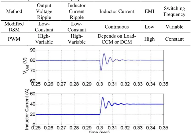
In order to evaluate dynamic performance of the buck DC-DC converter controlled by the proposed modified DSM method, the output voltage and inductor current of the buck DC-DC converter controlled by PWM and the proposed modified DSM methods for step load change from R = 4 Ω to R = 2 Ω are depicted and compared in Figs. 14 and 15, respectively. It is noteworthy to mention that the forgetting factor is considered as
ξ = 0.98 in the proposed modified DSM method. As shown in Fig. 14, the output voltage and inductor current ripple in the proposed modified DSM method are constant and the inductor current is continuous during step load change. On the other hand, as depicted in Fig. 15, the output voltage and inductor current ripple in the PWM method are changed during step load change. Furthermore, the buck converter operating mode in PWM method depends on the load and it operates in DCM mode for R = 4 Ω and operates in
Fig. 11 Output voltage noise frequency response spectrum for
PWM method in DCM and proposed DSM method.
Fig. 12 Inductor current for PWM method in DCM and
proposed DSM method.
Fig. 13 Buck converter input current for PWM method in
DCM and proposed DSM method.
Table 2 Comparison between the proposed modified DSM and PWM methods.
Method
Output Voltage Ripple
Inductor Current Ripple
Inductor Current EMI Switching Frequency
Modified DSM
Low-Constant
Low-Constant Continuous Low Variable
PWM
High-Variable
High-Variable
Depends on
Load-CCM or DCM High Constant
Fig. 14 The output voltage and inductor current of the buck converter controlled by the proposed modified DSM method for step load
change from R = 4 Ω to R = 2 Ω.
Iranian Journal of Electrical & Electronic Engineering, Vol. 14, No. 1, March 2018 34
CCM mode for R = 2 Ω. As shown in Fig. 14, during this load change, the transient time of the buck converter output voltage by using the proposed modified DSM method is 5ms.
The buck converter output voltage during converter startup for various values of ξ is depicted in Fig. 16. As shown in Fig. 16, the larger value of ξ results smooth and slower transient response whereas the smaller value of ξ results faster transient response with some oscillations.
The comparison between the proposed Control method based on Modified DSM method, the traditional PWM method with PI controller, and the presented DSM method in [19] is illustrated in Table 3.
Considering Table 3, the progress of applying proposed method on DC-DC converter, results in significant increase in quality of converter output voltage. Moreover, output voltage overshoot and switching noise are significantly improved in comparison with other mentioned methods. Hence, utilizing the proposed control method on buck converter leads to need smaller inductor for buck converter which causes significantly decrease in cost, size and emanated noise of converter. The simulation results confirm the feasibility of proposed control method based on modified DSM to enhance and improve the performance of DC-DC buck converter during various loads.
6 Conclusion
Even though various methods are introduced for improving the performance of PWM method, emanated harmonic clusters and sideband harmonics cause acoustic noise, harmonic heating effects, mechanical vibration, switching losses in the semiconductor and EMI. This paper has proposed improved control method based on modified DSM for buck converter to solve abovementioned problems. The main advantages of proposed method are as follows
1.Output voltage harmonic clusters and sideband harmonics are improved.
2.Switching noise peaks of the output voltage are decreased significantly.
3.The buck converter always works in CCM mode in presence of wide load variation.
4.The inductor current ripples are reduced drastically.
5.The transient response of buck converter output voltage is improved.
6.The current harmonic in converter input stage is modified.
These enhancements are achieved by applying improved control method based on proposed forgetting function to improve transient response of buck converter and also by using modified DSM to enhance harmonic spectrum of output voltage and reduce inductor current ripples. The simulation results confirm performance and feasibility of the proposed system.
Fig. 15 The output voltage and inductor current of the buck converter controlled by the PWM method for step load change from
R = 4 Ω to R = 2 Ω.
Fig. 16 The buck converter output voltage during converter startup for ξ = 0.85, ξ = 0.9, ξ = 0.95 and ξ = 0.98.
Iranian Journal of Electrical & Electronic Engineering, Vol. 14, No. 1, March 2018 35
Table 3 Comparison of the proposed control method based on modified DSM, the PWM with PI and presented DSM method in [19].
Parameters Proposed method PWM method Presented method in [19]
Output voltage 80 V 80 V 151 V
Output voltage THD 0.005% 4.5% 0.421%
First harmonic power -18 (dbm in 279 Hz) 41 (dbm in 558 Hz) -
Output voltage noise (rms) 0.012 V 5 V -
Output voltage overshoot 0 %35 -
Fundamental Inductor current 39.8 A 40 A 4.67 A
Inductor current THD 0.5% 36% 46%
References
[1] M. H. Rashid, Power electronics handbook: devices, circuits and applications. Academic press, 2010.
[2] M. Abarzadeh, H. M. Kojabadi, and L. Chang, “Small scale wind energy conversion systems,” in
Wind turbines: InTech, 2011.
[3] M. Abarzadeh, H. M. Kojabadi, and L. Chang, “Power Electronics in Small Scale Wind Turbine Systems,” in Advances in Wind Power: InTech, 2012.
[4] M. Abarzadeh, H. M. Kojabadi, and L. Chang, “Study of Novel Power Electronic Converters for Small Scale Wind Energy Conversion Systems,” in
Renewable Energy-Utilisation and System
Integration: InTech, 2016.
[5] J. Mooney, M. Halton, P. Iordanov, and V. O. Brien, “Dithered multi-bit sigma-delta modulator based DPWM for DC-DC converters,” in
2015 IEEE Applied Power Electronics Conference
and Exposition (APEC), pp. 2835–2839, 2015.
[6] J. Paramesh and A. v. Jouanne, “Use of sigma-delta modulation to control EMI from switch-mode power supplies,” IEEE Transactions on Industrial Electronics, Vol. 48, No. 1, pp. 111–117, 2001. [7] A. Hirota, S. Nagai, and M. Nakaoka, “A novel
delta-sigma modulated DC-DC power converter utilizing dither signal,” in IEEE 31st Annual Power
Electronics Specialists Conference. Conference
Proceedings (Cat. No.00CH37018), Vol. 2, pp. 831–
836, 2000.
[8] A. Carlosena, W. Y. Chu, B. Bakkaloglu, and S. Kiaei, “Randomized Carrier PWM With Exponential Frequency Mapping,” IEEE Transactions on Power Electronics, Vol. 22, No. 3, pp. 960–966, 2007.
[9] Y. Choi, H. Jeon, and Y. B. Kim, “A switched-capacitor DC-DC converter using delta-sigma digital pulse frequency modulation control method,” in
IEEE 56th International Midwest Symposium on
Circuits and Systems (MWSCAS), pp. 356–359,
2013.
[10]A. Congiu, E. Bodano, and M. Barbaro, “A Delta-Sigma Dithering-Amplification-Based Identification Technique for Online SMPS,” IEEE Transactions on Power Electronics, Vol. 31, No. 8, pp. 5992– 6001, 2016.
[11]A. Dashtestani and B. Bakkaloglu, “A Fast Settling Oversampled Digital Sliding-Mode DC-DC Converter,” IEEE Transactions on Power Electronics, Vol. 30, No. 2, pp. 1019–1027, 2015. [12]A. Hirota, S. Nagai, and M. Nakaoka, “A novel
delta-sigma modulated DC-DC power converter operating under DC ripple voltage,” in Industrial Electronics Society, 1999. IECON '99 Proceedings. The 25th Annual Conference of the IEEE, Vol. 1, pp. 180–184, 1999.
[13]A. Hirota, S. Nagai, and M. Nakaoka, “A simple configured reducing noise peak DC-DC converter introducing delta-sigma modulation circuit,” in
Twentieth Annual IEEE Applied Power Electronics
Conference and Exposition, 2005. APEC 2005., Vol.
3, pp. 1515–1519, 2005.
[14]W. Yan, W. Li, and R. Liu, “A Noise-Shaped Buck DC-DC Converter With Improved Light-Load Efficiency and Fast Transient Response,” IEEE Transactions on Power Electronics, Vol. 26, No. 12, pp. 3908–3924, 2011.
[15]C. Tao and A. A. Fayed, “A Low-Noise PFM-Controlled Buck Converter for Low-Power Applications,” IEEE Transactions on Circuits and Systems I: Regular Papers, Vol. 59, No. 12, pp. 3071–3080, 2012.
[16]E. N. Y. Ho and P. K. T. Mok, “Design of PWM Ramp Signal in Voltage-Mode CCM Random Switching Frequency Buck Converter for Conductive EMI Reduction,” IEEE Transactions on Circuits and Systems I: Regular Papers, Vol. 60, No. 2, pp. 505–515, 2013.
[17]C. Tao and A. A. Fayed, “A Buck Converter With Reduced Output Spurs Using Asynchronous Frequency Hopping,” IEEE Transactions on Circuits and Systems II: Express Briefs, Vol. 58, No. 11, pp. 709–713, 2011.
[18]Z. Lukic, N. Rahman, and A. Prodie, “Multibit Sigma-Delta PWM Digital Controller IC for DC-DC Converters Operating at Switching Frequencies Beyond 10 MHz,” IEEE Transactions on Power Electronics, Vol. 22, No. 5, pp. 1693–1707, 2007. [19]A. Hirota, S.-P. Mun, S.-K. Kwon, and M.
Nakaoka, “Output voltage switching noise peaks and utility AC input harmonic current characteristics of delta-sigma modulated AC-DC converter with boost-buck circuit topologies,” in Energy Conversion Congress and Exposition, pp. 934-939: IEEE, 2009.
Iranian Journal of Electrical & Electronic Engineering, Vol. 14, No. 1, March 2018 36
[20]L. Corradini, A. Bjeletić, R. Zane, and D. Maksimović, “Fully Digital Hysteretic Modulator for DC-DC Switching Converters,” IEEE Transactions on Power Electronics, Vol. 26, No. 10, pp. 2969–2979, 2011.
[21]A. Hirota and M. Nakaoka, “A study of soft switching DC-DC converter under delta-sigma modulation,” in 18th European Conference on Power
Electronics and Applications (EPE'16 ECCE Europe), pp. 1–5, 2016.
[22]A. Hirota, K. Soon-Kurl, S. Nagai, S. Chandhaket, and M. Nakaoka, “A novel type suppressed noise peak DC-DC boost converter introducing delta-sigma modulation technique,” in IEEE Ninth International Conference on Power Electronics and Drive Systems, pp. 534–537, 2011.
[23]N. A. Keskar and G. A. RincÓn-Mora, “A Fast, Sigma-Delta Boost DC-DC Converter Tolerant to Wide LC Filter Variations,” IEEE Transactions on Circuits and Systems II: Express Briefs, Vol. 55, No. 2, pp. 198–202, 2008.
[24]J. J. Chen, Y. S. Hwang, C. S. Jheng, Y. T. Ku, and C. C. Yu, “A Low-EMI Buck Converter with Continuous-Time Delta-Sigma-Modulation and Burst-Mode Techniques,” IEEE Transactions on Industrial Electronics, Vol. PP, No. 99, pp. 1–1, 2018.
[25]Y. Sadanda, T. Okuda, and T. Hikihara, “Direct drive of a buck converter by delta-sigma modulation at 13.56-MHz sampling,” in IEEE 18th Workshop on Control and Modeling for Power Electronics
(COMPEL), pp. 1–4, 2017.
[26]Y. S. Hwang, J. J. Chen, W. J. Hou, P. H. Liao, and Y. T. Ku, “A 10-us Transient Recovery Time Low-EMI DC-DC Buck Converter With Delta-Sigma Modulator,” IEEE Transactions on Very Large Scale Integration (VLSI) Systems, Vol. 24, No. 9, pp. 2983–2992, 2016.
[27]S. Lefteriu and C. Labarre, “Transfer function modeling for the Buck converter,” in IEEE 20th Workshop on Signal and Power Integrity (SPI), pp. 1–4, 2016.
[28]M. José and R. del Río, CMOS sigma-delta converters: Practical design guide. John Wiley & Sons, 2013.
[29]D. A. Johns and K. Martin, Analog integrated circuit design. John Wiley & Sons, 2008.
M. Abarzadeh (S’15, M’16) received the
B.Sc., M.Sc., and Ph.D. (All with Hons.) degrees in Electrical Engineering from the Sahand University of Technology (SUT), Tabriz, Iran, in 2008, 2011, and 2016, respectively. Since 2016, he has been an Assistant Professor at Electrical Engineering Faculty of SUT. He has authored or co-authored over 25 journal and conference papers and book chapters, and holds four patents. His current research interests include renewable energy conversion, power electronic converters and their applications in power grid, variable-speed motor drives, and control systems. He was selected by the SUT as Distinguished Student in 2010 and 2012. He is a member of the National Institute of Elites, which is the greatest hub of Iranian Elites.
F. Eshaghi received the B.S. and M.Sc.
degrees in Electrical Engineering from the University of Tabriz, Tabriz, Iran, in 2011 and 2013, respectively. She is currently working toward the Ph.D. degree in the analog and digital circuit design for biomedical applications at Sahand University of Technology, Tabriz, Iran. Her research interests include Delta Sigma Converters, Low power circuit design and digital signal processing for biomedical purposes.
E. Najafi Aghdam was born in Zonouz,
Iran, in 1964. He received the B.E. degree from University of Sistan and Baluchestan, Zahedan, Iran, in 1990, and the M.S. degree from Amir Kabir University of Technology, Tehran, Iran, in 1994, both in Electronic Engineering. In 1995, he joined the Faculty of Electrical Engineering at Sahand University of Technology, Tabriz, Iran, as a Lecturer. In 2002, he started his Ph.D. program dealing with a high performance band pass Delta Sigma ADC. The research program was directed by Prof. P. Benabes at SUPELEC, France. Esmaeil Najafi Aghdam is now an Associate Professor at Sahand University of Technology. His current research interests include mixed mode electronic circuits, Delta Sigma Converters, RFIC design, Ultrasonic circuits and Electronic measurement.
![Table 3 Comparison of the proposed control method based on modified DSM, the PWM with PI and presented DSM method in [19]](https://thumb-us.123doks.com/thumbv2/123dok_us/24977.2002760/8.595.49.545.95.182/table-comparison-proposed-control-method-modified-presented-method.webp)