80 | P a g e M12-1-1-4-2014
Journal homepage: www.mjret.in
ISSN: 2348-6953
Sachin Ghodke Electrical Engineering KJ College of Engineering and Management Research.
Pune, India
Energy Efficient Solar System
Mahesh Vasant Rajole Electrical Engineering KJ College of Engineering and Management Research. Pune, India
Deepak S Pagar, Electrical Engineering KJ College of Engineering and Management Research. Pune, India
Meghraj Popat Makone Electrical Engineering KJ College of Engineering and Management Research. Pune, India
Prof. Mohit Kumar Electrical Engineering KJ College of Engineering and Management Research. Pune, India
Abstract
This paper shows the potential benefits of the solar tracking system by using real time clock and microcontroller. This method is developing the systems that increase the efficiency of the system that tracks the sun rays in to its right angle. The solar tracking system is designed and experimentally tested.81 | P a g e M12-1-1-4-2014
1. INTRODUCTION
The electricity is generated by developing the photovoltaic material and subsequent development of solar cell- a semiconductor material that converts a direct light in to the direct current. By using solar arrays a series, a series connected solar cells generated a dc voltage that directly connected to the load.
This alternative power source is in the recent years achieving a greater popularity especially the realization of shortcomings of the fossil fuels and other generating of energy resources. The use of renewable energy to generate electrical energy by recent 75 to 100 of years. By using this system we can reduce the converter losses, storage losses and light gathering losses. The light gathering is dependent on the angle of incident of sun rays and the solar cell surface, when the sun rays are perpendicular to the surface of the solar plate then the efficiency of the solar cell is maximum. The main objective to create this system to reduce the incident angle between the sunrays and solar cell.
2. ANGEL OF ROTATION
Total angel of rotation in 12 Hours = 180 Degree
So angle of rotation in 1 hr. = 180/12 = 15 Degree Hence we give 1 hr Delay to dc motor by programming of microcontroller and panel
rotate every one hour and panel adjust perpendicular to the sun rays.
Fig. No. 1 Schematic Diagram of Solar Tracking System
C
R7 RESISTOR SIP 9
1 2 3 4 5 6 7 8 9 5V 12v C R7 RESISTOR SIP 9
1 2 3 4 5 6 7 8 9 U3 L298 1 2 3 4 5 6 7 8 9 10 11 12 13 14 15 ISENSE A OUTPUT1 OUTPUT2 VC C INPUT 1 INH1 INPUT 2 GN D VR EF INPUT 3 INH2 INPUT 4 OUTPUT3 OUTPUT4 ISENSE B D4 S3 LEFT R12 10K D5 D1 VT D4 IN4007 LM7805 1 3 2 VIN VOUT AD J EN R3 10k 1 3 2 +5V S4 RIGHT Y 1 11.059Mhz R10 1K MICROCONTROLLER D14 1N4007 D7 U2 AT89C51 9 18 19 20 29 30 31 40 1 2 3 4 5 6 7 8 21 22 23 24 25 26 27 28 10 11 12 13 14 15 16 17 39 38 37 36 35 34 33 32 RST XTAL2 XTAL1 GN D PSEN ALE/PROG EA/VPP VC C P1.0 P1.1 P1.2 P1.3 P1.4 P1.5 P1.6 P1.7 P2.0/A8 P2.1/A9 P2.2/A10 P2.3/A11 P2.4/A12 P2.5/A13 P2.6/A14 P2.7/A15 P3.0/RXD P3.1/TXD P3.2/INTO P3.3/INT1 P3.4/TO P3.5/T1 P3.6/WR P3.7/RD P0.0/AD0 P0.1/AD1 P0.2/AD2 P0.3/AD3 P0.4/AD4 P0.5/AD5 P0.6/AD6 P0.7/AD7 5V DC3 0.1uf RS D2 LED DC MOTOR R5 1K D2 SOLAR PANEL LCD 16x2 VCC S5 ENTER D6 BT2 6 V BATTERY
1 2 5V D3 C3 33pf M1 MOTOR1 5V D0 RW D8 LED J1 LCD 16X2 1 2 3 4 5 6 7 8 9 10 11 12 13 14 15 16 D9 IN4007 D11 1N4007 J1 CON3 1 2 3 S1 INC RS +5V C4 1000uf /35v C1 10uF/63V EN D15 1N4007 D10 IN4007 CR6 10k/9pin 1
2 3 4 5 6 7 8 9
82 | P a g e M12-1-1-4-2014
3. Description of Circuit Diagram
Fig No.1 shows The Actual circuit of the solar Tracking system Project, and the Working of the system is given below The RTC Gives Real time clock pulse signal on hourly basis to the microcontroller and microcontroller detect this signal and operate the DC Motor through the L298 Driver IC Then solar panel rotate at appropriate speed set as per microcontroller programming and it holds the solar panel perpendicular to the sun rays whole day, and gives maximum power output as compare to fixed panel. Solar panel will convert sun rays into electricity. Battery will be charged through solar panel. Stored charged will be used as a power source for working of circuit. RTC will continuously detect time and will provide signal to micro-controller. Micro-controller will drive the motor as per table. The time will be displayed on the LCD display connected to micro- controller. By using inverter we can connect AC load to system.
4. RESULT
Table No. 1 tracking System
Sr.No. TIME VOLTAGE (V) CURRENT (A) POWER (W)
1 7am 1O 0.11 1.1
2 8 17 0.50 8.5
3 9 17.5 0.53 9.01
4 10 17.5 0.54 9.18
5 11 18 0.6 10.8
6 12pm 18 0.6 10.8
7 1 18.5 0.63 11.65
8 2 18 0.59 10.62
9 3 18 0.58 10.44
10 4 17.5 0.55 9.62
11 5 17.4 0.53 9.22
12 6 9.8 0.10 0.98
13 7 3 0.04 0.12
83 | P a g e M12-1-1-4-2014
Sr.No TIME VOLTAGE (V) CURRENT (A) POWER (W)
1 7am 8 0.09 0.72
2 8 10 0.11 1.1
3 9 11 0.20 2.2
4 10 12 0.25 3
5 11 14 0.40 5.6
6 12pm 17 0.50 8.5
7 1 18 0.60 10.8
8 2 18 0.59 10.62
9 3 16 0.55 8.8
10 4 16 0.54 8.64
11 5 14 0.41 5.74
12 6 8 0.9 0.72
13 7 4 0.04 0.60
TOTAL 12 Hours 66.66W/D
Table No. 2 Fixed System
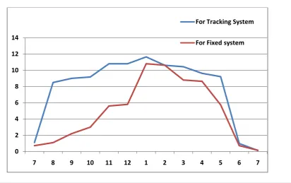
5. POWER OUTPUT COMPARISION BETWEEN FIXED AND TRACKING
SYSTEM ON 22 & 23 MARCH 2014
Scale: On X-axis:1cm=1hr, On Y-axis:1cm=2watt
0 2 4 6 8 10 12 14
7 8 9 10 11 12 1 2 3 4 5 6 7
For Tracking System
84 | P a g e M12-1-1-4-2014
From the above graph we can see that the tracking system gives maximum power output between 9 am to 5 pm. And other graph show the maximum output only 12 pm to 4 pm. So the we conclude that the tracking system is better energy efficient solar system than fixed panel system.
6. CONCLUSION
A solar tracking system is design to employ the new principle of self-adjusting features of solar cell as a light sensor as well as providing various indications of their relative angles to the sun rays by detecting the voltage output. By using this system we can increase the efficiency of the solar cell 30% more than the tracking system.
7. ACKNOWLEGEMENT
We would like to thank the Electrical Engineering faculty members at KJ College of Engineering & Management Research Pune who helped create this project Prof.N.M.Lokhande.
Finally, we thank Prof.Mohit Kumar Shakya for all his patience and everlasting help.
REFERENCES
[1] Fahrenburch, A. and Bube, R. 1983, Fundamentals of solar cells, Academic Press, New York. [2] Partain, L.D. 1995, Sollar Cells and their applications, John Wiley & Sons. New York.
[3] E Weise, R Klockner, R Kniel, Ma Sheng Hong, Qin Jian Ping, “Remote Power Supply Using Wind and Solar energy – a Sino-German Technical Cooperation Project”, Beijing International Conference on Wind Energy, Beijing, 1995
[4] Wichert B, Lawrance W, Friese T, First Experiences with a Novel Predictive Control Strategy for PV-Diesel Hybrid Energy Systems, Solar’99
[5] Duryea S, Syed I, Lawrence W, An Automated Battery Management System for Photovoltaic Systems, International Journal of Renewable Energy Engineering, Vol 1, No 2, Aug 1999
[6] Twidell J, Weir J, Renewable Energy Systems, Chapman and Hall, 1994
[7] Centre for Resources and Environmental Studies, ANU, Sustainable Energy Systems – Pathways for Australian Energy Reforms, Cambridge University Press, 1994