bcoulibaly28@yahoo.fr 2.National School of Engineers, Department of Industrial Engineering, Bamako, Mali.
sidibebernard@yahoo.fr 3.University of Technical and Technological Sciences, Faculty of Technical Sciences, Physical
Department, Bamako, Mali. berthemoni@yahoo.fr
Abstrat :The manipulator provides a gain in terms of production rate compared to conventional serial manipulators. The trajectory planning made it possible to optimize the performance of the parallel 3RRR manipulator in its workspace. This planning was done on the octave software, based on the modeling of the manipulator using the inverse geometry method. Which allowed to determine the workspace of the robot. The working space of a parallel robot therefore depends on the different independent kinematic chains that connect the base to the effector (mobile platform). Key words: 3RRR parallel manipulator, trajectory planning, modeling, independent kinematic chains, Works pace. I. Introduction
In recent years, parallel robots have received considerable attention for various research and applications. Parallel manipulators are closed-loop mechanisms in which separate serial chains (links and joints) are connected to both the fixed base and the mobile platform.
Figure 1: The geometric representation of the parallel robot 3RRR.
International Journal of Research Publications
Volume-41, Issue-1,November 2019
Accepted and Published Manuscript
Planning the trajectory of the 3RRR manipulator
Coulibaly Bourama, Marie Bernard Sidibé, Kya Abraham Berthé
PII : Coulibaly Bourama.100411112019828 DOI: 100411112019828
Web: http://ijrp.org/paper-detail/829
To appear in: International Journal of Research Publication (IJRP.ORG)
Received date: 29 Nov 2019 Accepted date: 04 Dec 2019 Published date: 05 Dec 2019
Please cite this article as: Coulibaly Bourama, Marie Bernard Sidibé, Kya Abraham Berthé , Planning the trajectory of the 3RRR manipulator , International Journal of Research Publication (Volume: 41, Issue: 1), http://ijrp.org/paper-detail/829
This is a PDF file of an unedited manuscript that has been accepted for publication. As a service to our customers we are providing this final version of the manuscript.
Planning the trajectory of the 3RRR manipulator
Bourama Coulibaly
1, Marie Bernard Sidibé
2, Kya Abraham Berthé 3
1. Research and Training Center for the Textile Industry (CERFITEX), Department of
Electricity, Electronics and Automation (EEA) Ségou, Mali. bcoulibaly28@yahoo.fr
2. National School of Engineers, Department of Industrial Engineering, Bamako, Mali.
sidibebernard@yahoo.fr
3. University of Technical and Technological Sciences, Faculty of Technical Sciences, Physical
Department, Bamako, Mali. berthemoni@yahoo.fr
Abstrat :The manipulator provides a gain in terms of production rate compared to conventional serial manipulators. The trajectory planning made it possible to optimize the performance of the parallel 3RRR manipulator in its workspace. This planning was done on the octave software, based on the modeling of the manipulator using the inverse geometry method. Which allowed to determine the workspace of the robot. The working space of a parallel robot therefore depends on the different independent kinematic chains that connect the base to the effector (mobile platform).
Key words: 3RRR parallel manipulator, trajectory planning, modeling, independent kinematic chains,
Works pace.
I. Introduction
In recent years, parallel robots have received considerable attention for various research and applications. Parallel manipulators are closed-loop mechanisms in which separate serial chains (links and joints) are connected to both the fixed base and the mobile platform.
Figure 1: The geometric representation of the parallel robot 3RRR.
Source: Nantes Institute for Research in Communications and Cybernetics / 2010
The angles αi and θi define the angular position of the segments of the leg i, i Є [1, 2,3], which depend
on the relative position of the anchor points Ai, Bi, and Ci, illustrated in figure1. In order to simplify the
resolution, one places oneself in the fixed landmark of origin O. The axis of this landmark is carried by the axis of rotation of the center pivot link Ai. The Cartesian coordinates of the points Ci are known because these points are related to the effector whose orientation is known, but is expressed in the reference (x, y, z) of the origin C1 illustrated in FIG. It is necessary to express the coordinates Ci in this
reference, which is obtained by a rotation of angle Φ around the axis x [3].
This article highlights the various possible movements of the manipulator in order to predict or plan its trajectory based on a modeling of the manipulator by the inverse geometry method.
II. Parallel 3RRR manipulator architecture
The minimal architecture for a parallel 3RRR robot requires three actuators to drive the three main rotations in the Cartesian space illustrated in Figure 2. Important data for a robot is the expression of the values that must be taken by the controlled actuators to reach the desired configuration. [2]
This information is called the Geometric Problem, it gives the link between the quantities controlled by the actuators called joint coordinates and the state variables of the robot that we want to control called Cartesian coordinates.
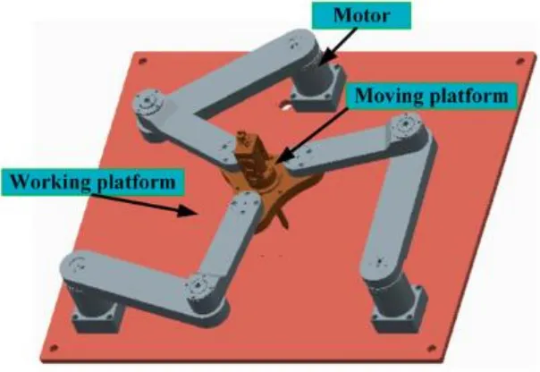
Figure 2: Architecture of a Parallel 3RRR Robot.
Source: Article by Lia chao Sheng and Wei Li (Optimization Design by Genetic Algorithm Controller for Trajectory Control of a 3-RRR Parallel Robot)
III. Modeling the parallel 3RRR robot by inverse geometry
This method is based on the Denavit and Hartenberg convention (DH 1955).
It allows the passage between adjacent joints of a robotic system. It concerns open kinematic chains where the joint has only one degree of freedom, and the adjacent surfaces remain in contact. For this aspect the use of hinges or slides is essential. The appropriate choice of reference points in the links
facilitates the calculation of the matrices and makes it possible to quickly express information from the terminal element to the base or vice versa. [4]
From Figure 1 we can write the following equation:
OAi + AiCi = OP + PCi (1)
For i = 1, 2 and 3, we can write the following two matrices of transformations:
The Cartesian coordinates P (PXF, PYF) correspond to the position of the effector in the fixed reference. In addition, the two matrices are equal, so the equation becomes:
With bxi = nicosγi and byi = nisinγi. By squaring the two lines of equation (4) we obtain easily after simplification the following equation:
L21i - 2PYp oyi - 2PXp oxi + b2Xi + b2yi + o2Xi + o2yi + P2Xp + P2Yp + 2L1i byi [sin (ɸ - Ѳi) -
cos (ɸ - Ѳi)] + 2cos ɸ (PXp bXi + PYp byi - bxi oxi - byi oyi) + 2sin (ɸ) (PYp bxi - PXp byi - byi oyi +
byi oxi) + 2l1i · cosѲi (oxi - PXp) + 2L1i • sin Ѳi (oyi - PYp) - L22i = 0 (5)
For the calculation of the inverse geometric model, equation 5 can be written in the form:
AisinѲi + Bicos Ѳi = Ci
With :
Bi=2L1i ( oxi
–
byi *sin(ɸ) –
bxi* cos(ɸ) +
PXp)
Ci=
–
[L21i
–
2PYp oyi
–
2PXp oxi + b2Xi + b2yi + o2xi + o2yi + P2Xp + P2Yp
–
L22i +
2*cos ɸ( Pxp bxi + PYp byi –
bxi oxi
–
byi oyi ) +2sin(ɸ)( PYp bxi –
PXp byi
–
byi oyi + byi
oxi ).
Ѳi=Atan2 (Ai, Bi) ±Atan2 ( ) (7)
Equation 7 presents two possible solutions for each arm so we have eight (8) possible solutions for the 3RRR robot.
The rotation of active and passive joints is obtained by theoretical equations above. So we can go to the simulation on the octave software.
VI. Simulation
This program includes several MATLAB scripts used for the simulation of 3-RRR parallel manipulators. The program consists of interactively defining the position and orientation of the mobile platform. At each change of pose, the inverse kinematic problem is solved and the new configuration is drawn. In addition, at each change of orientation of the mobile platform, the work space of constant orientation is calculated and plotted.
1. 3RRR Robot Settings
Arm length:
l1i = 7.2cm l2i = 9.6cm
For the calculation of triangle parameters, we used the sinus law [2]:
And the cosine law:
2. Origin coordinate
ox1 = 0cm, ox2 = 24.3cm, ox3 = 1.903510807cm; oy1 = 0cm, oy2 = 0 cm, oy3 = 24.09994339 cm,
3. Parameter of the triangle
n = 5.820652885cm, n = 5.820652885cm, n = 3.810511777 cm; γ1 = 220.8933947 degree, γ2 =
-40.933947 degree, γ3 = 90 degree; Φ = 0 degree;
4. The walk of the parallel 3RRR Manipulator
Thus, the course of the parallel 3RRR manipulator according to cartesian coordinates of the effector or the mobile platform is determined. The range of possible movements of the manipulator is between the two cartesian coordinates of the effector (departure threshold and arrival threshold) of the table below.
TableI: The possible movements of the manipulator.
In TableI above, which represents the set of possible paths of the mobile platform or the effector between the two Cartesian coordinates P1 (6, 5) and P2 (16,15). Between these two coordinates, there are several possible movements of the manipulator. For example, a simulation of the three movements of the mobile platform of the robot is shown below:
Cordonné of Departure
Cordonnee of arrival
(6 ,5)
(16,15)
5. The working space of each arm of the parallel robot
Using numerical simulations, the complete workspace is identified for each arm of the manipulator shown above.
6. The manipulator's working space
This is the total workspace obtained by intersecting three regions of the robot's legs
Thus, the workspace of the parallel 3RRR manipulator is summarized in the following figure:
V. Conclusion
The planning of the 3RRR parallel manipulator workspace depends on the working space of each arm of the manipulator. The analysis of the robot's work space led to a high performance and a better positioning of the platform in order to optimize the trajectory of the manipulator. A modeling of the manipulator by the inverse geometry method was presented to determine the inverse kinematics.
References
[1] Chen wenjia et al “A novel 4-DOF parallel manipulator and its kinematic modeling.” Proceedings
of the 2000 IEEE conference on robotics and automation.
[2] Xin-Jun Liu and Jongwon Kim “ A new three-degree-of-freedom of parallel manipulator.”
Proceedings of the 2002 IEEE conference on robotics and automation.
[3] X. J. Liu and J. Kim “A new three-degree-of-freedom parallel manipulator” Proceedings of the 2002 IEEE conference on robotics and automation.
[4] P.Ben Horin, S. Djerassi, M. Shoham and R. Ben Horin “Dynamics of six degrees-of-freedom
parallel robot actuated by three two wheel cart” Multibody syst Dyn (2006).
[5] Configuration de la prise d’origine,
[6].J-P. Merlet. Parallel Robots. Springer, 2006. (Cité pages 3 et 17.)