52
INTRODUCTION
In helical gears, the width of gear wheels ranges from 0.2 to 1.4 of the pitch diameter of a rack and it depends on the position of the gear wheels relative to supports and the hard-ness of the gear teeth. An increase in the width of the gears leads to an increase in the length of the contact line and the total tooth contact ratio, which results in a higher load-carrying capacity and durability of the gear. The over-lap ratio εβ depends on the width of the gear wheel and tooth inclination angle. To ensure constant load on the teeth during gear opera-tion, in practice the constant load on the teeth during gear operation, in practice the width of the gear wheel must be selected such that the minimum length of the contact line can be maintained constant. The literature [1–15] of the subject offers hardly any studies on this problem, particularly when it comes to gears with profile correction.
FORMULATION OF THE PROBLEM AND
ITS SOLUTION
The total tooth contact ratio of a helical gear is εγ = εα + εβ, where:
1 2
1
2
be e
r
α
+
ε =
π
,sin
W
b
m
β
β
ε =
π
, (1) Where εα is the end-face tooth contact ratio; εβ is the overlap ratio; 2 21 1s b1 w1
sin
we
=
r
−
r
−
r
α
is the length of tooth contact at the end of engage-ment;
e
2=
r
202−
r
b22−
r
w2sin
α
w is the length of tooth contact at the start of engagement; rw1, rw2 are the radii of the pitch circles of the pinion and gear, respectively; r1s= ra1 – r, r20 = ra2 – r; r = 0.2 m is the rounding radius of the top land of a gear tooth;r
b1=
r
1cos
α
tis the radius of the base circle in the pinion;r
b2=
r
2cos
α
tis the radius of the base circle in the gear;r mz
1=
1/ 2cos
β
is the radius of the pitch circle in the pinion;Computer Simulation of the Impact of Optimization of Width
in the Helical Cylindrical Gear on Bearing and Durability
Part 1. Height Correction of the Gear Profile
Myron Czerniec
1*1 Institute of Information Technology Systems, Lublin University of Technology, ul. Nadbystrzycka 36, 20-618
Lublin, Poland
* Corresponding author’s e-mail: [email protected]
ABSTRACT
Based on the elaborated calculation method he authors method for determining the wear and durability of gears was employed to measure the maximum contact pressures, linear wear of teeth and durability of the
gear with height correction of the profile. The optimal condition width in involute helical gears is indicated ensuring constant length of the line of contact between the meshing gears. As a result, it was possible to
de-termine variations in the parameters for the optimized gear describing the meshing gears at different values of the profile correction coefficients.
Keywords: block calculation method, helical cylindrical gear, height correction of engagement, optimal gear width, maximum contact pressures, tooth wear, gear durability
Volume 13, Issue 1, March 2019, pages 52–59
https://doi.org/10.12913/22998624/99037
Advances in Science and Technology
Research Journal
53
2 2
/ 2cos
r mz
=
β
is the radius of the pitch circle in the gear; ra1=r1+mis the addendum radius of the pinion;r
a2= +
r m
2 is the addendum radius of the gear; β is the inclination angle of the teeth; bW is the width of the pinion; m is the engagement modulus; z1, z2are the numbers of gear teeth; αt is the end-face pressure angle; αw is the pressure angle of the corrected profile.Hence, the length of the contact line during teeth engagement will be constant if εβ = const (1 or 2). Accordingly, using the above formula of εβ, the width of gear teeth is calculated as:
β π = sin m
bW when εβ = 1. (2)
The minimum length of contact between a pair of teeth is calculated using the formula [18]:
min
cos
W1
b
n n
b
l
α α βα β
ε
=
−
β
ε ε
whenn
α+
n
β≤
1
, (3) where nα,nβ are the fractional parts of the coef-ficients εα,εβ.What follows is the analysis of two helical cy-lindrical gears with profile correction described by two different widths of gear wheels: lmin = const when εβ = 1 and bW = 54.275 mm (according to (2)); lminlmin≠const when εβ <1 and bW = 30 mm. The gear with bW = 54.275 mm is described by triple-double-triple engagement while that with bW = 30 mm by double-single-double engagement.
The angles of transition from double engage-ment (
∆ϕ
1F2) to single and then, again, to double engagement (∆ϕ
1F1) are calculated in the follow-ing way:2 2 1 1
1F 10 1F
,
1F 10 1F,
∆ϕ = ϕ − ϕ
∆ϕ = ϕ + ϕ
(4) where:2 2 1 1
1F
tan
Ftan ,
w 1Ftan
Ftan ,
wϕ =
α −
α ϕ =
α −
α
where 1 2 1 2 b e e r + = ,
sin
Wb
m
=
, (1)
is the end-face tooth contact ratio; is the overlap ratio;
e
1=
r
12s−
r
b21−
r
w1sin
w is the length oftooth contact at the end of engagement; 2 2
2 20 b2 w2
sin
we
=
r
−
r
−
r
is the length of tooth contact at the start of engagement; rw1,rw2 are the radii of the pitch circles of the pinion and gear, respectively;,
1
1 r r
rs = a − r20=ra2−r ; r=0,2m is the rounding radius of the top land of a gear tooth; rb1=r1costis the radius of the base circle in the pinion; rb2 =r2costis the radius of the base circle in the gear;
1 1/ 2cos
r mz= is the radius of the pitch circle in the pinion; r mz2 = 2/ 2cos is the radius of the pitch circle in the gear; ra1=r1+mis the addendum radius of the pinion; ra2 = +r m2 is the addendum radius of the gear; is the inclination angle of the teeth; bW is the width of the pinion;
m
is the engagement modulus; z z1, 2are the numbers of gear teeth; tis the end-face pressure angle; wis the pressure angle of the corrected profile.Hence, the length of the contact line during teeth engagement will be constant if = const (1 or 2).
Accordingly, using the above formula of , the width of gear teeth is calculated as
=
sin m
bW when = 1. (2)
The minimum length of contact between a pair of teeth is calculated using the formula [18]:
min cosW 1
b
n n b
l
= −
when
n
+
n
1
, (3)where n,nare the fractional parts of the coefficients ,.
What follows is the analysis of two helical cylindrical gears with profile correction described by two different widths of gear wheels: lmin= const when = 1 and bW = 54.275 mm (according to (2)); lmin
const when 1 and bW = 30 mm. The gear with bW = 54.275 mm is described by triple-double-triple engagement while that with bW = 30 mm by double-single-double engagement.
The angles of transition from double engagement (
1F2) to single and then, again, to double engagement (
1F1) are calculated in the following way:2 2 1 1
1F 10 1F
,
1F 10 1F,
= −
= +
(4)where
=
1F2tan
−
F2tan ,
=
w 1F1tan
−
F1tan ,
w 10=tant10 −tanw;2 1
1 1 1 2
1 1
sin ( ) 0.5 sin ( ) 0.5
tan , tan ,
cos cos
w w b b w w b b
F F
r p e n p r p e n p
r r
− − + − − −
= =
cos / cos
b w
p = m is the tooth pitch; = 20O is the pressure angle.
The angle 1Edescribing the end of engagement is
1E 10 1E,
= + where =1E tan −E tan ,w E =arccos(rb1/r1s). In the case of triple-double-triple engagement
2 1
1 1 1 2
1 1
sin ( ) 0.5 ( 1) sin ( ) 0.5 ( 1)
tan , tan .
cos cos
w w b b w w b b
F F
r p e p r p e p
r r
− − + − − − − −
= =
After the height correction of engagement, the addendum radii:
1 1 (1 1) , 2 2 (1 2)
a a
r = + +r x m r = + +r x m (5) where x1 = −x2 are the coefficients of displacement (correction) of the profile.
;
2 1
1 1 1 2
1 1
sin
(
) 0.5
sin
(
) 0.5
tan
, tan
,
cos
cos
w w b b w w b b
F F
r
p e
n p
r
p e
n p
r
r
β βα −
−
+
α −
−
−
α =
α =
α
α
2 11 1 1 2
1 1
sin
(
) 0.5
sin
(
) 0.5
tan
, tan
,
cos
cos
w w b b w w b b
F F
r
p e
n p
r
p e
n p
r
r
β β
α −
−
+
α −
−
−
α =
α =
α
α
cos
/ cos
b w
p
= π
m
α
β
is the tooth pitch; α = 20O is the pressure angle.The angle
∆ϕ
1E describing the end of en-gagement is1E 10 1E
,
∆ϕ = ϕ + ϕ
where
ϕ =
1Etan
α −
Etan ,
α
w αE =arccos(rb1/r1s) In the case of triple-double-triple engagement2 1
1 1 1 2
1 1
sin
(
) 0.5 (
1)
sin
(
) 0.5 (
1)
tan
, tan
.
cos
cos
w w b b w w b b
F F
r
p e
p
r
p e
p
r
r
β βα −
−
+
ε −
α −
−
−
ε −
α =
α =
α
α
2 11 1 1 2
1 1
sin
(
) 0.5 (
1)
sin
(
) 0.5 (
1)
tan
, tan
.
cos
cos
w w b b w w b b
F F
r
p e
p
r
p e
p
r
r
β β
α −
−
+
ε −
α −
−
−
ε −
α =
α =
α
α
After the height correction of engagement, theaddendum radii:
r
a1= + +
r
1(1
x m r
1) ,
a2= + +
r
2(1
x m
2)
(5)where
x
1= −
x
2 are the coefficients of displace-ment (correction) of the profile.Other parameters of the gear are the same as those in the gear without profile correction.
The changes in the initial maximum contact pressures pfmax during one cycle of tooth engage-ment are determined using the method for deter-mining the wear and durability of toothed gears [16, 17], considering the profile correction and the type of engagement [18]. This is done using the Hertz formula:
max
0.418
/
j j
p
=
N E
′
ρ
, (6)where
N
′ =
N l w
/
min ,N T K r
=
nom g/ cos
w1α
w is the force acting in tooth engagement;1
9550 /
=
nomT
P n
is the rated torque on the drive shaft; P is the power on the drive shaft; n1 is the number of revolutions of the drive shaft; Kg is the dynamic coefficient; E is Young’s modulus of steel teeth; lmin is the minimum length of a line of contact; j = 0, 1, 2, …, s are the points of contact on the tooth profile; w is the number of engage-ment pairs which transmit power simultaneously; ρj is the reduced radius of curvature of the tooth profile in normal section; ρ1j, ρ2j are the radii of curvature of the side profiles of the teeth of the pinion and gear, respectively1 2 1 2 j j j j j
ρ ρ
ρ =
ρ + ρ
1 1jcos
t jb
ρ
ρ =
β
2 2j
cos
t jb
ρ
ρ =
β
, (7) where(
tan cos
)
,
arctan
tan
cos
b
arc
t t
α
β =
β
α
α =
Advances in Science and Technology Research Journal Vol. 13(1), 2019
54
1 1
tan
1t j
r
b t jρ =
α
,(
)
2 22 2 2
/
2cos
t j
r
wr r
j w wρ
=
−
α
,(
)
1
arctan tan
10t j t
j
α =
α + ∆ϕ
,(
)
(
)
2 210 20 2
tan 1 tan / cos
cos
t w w w
w
u
u r r
α = + α − − α
α
(
)
2 2
2j w 1j
2
w j1cos
w t j1r
=
a
+
r
−
a r
α − α
,1j w1
cos
w/ cos
t j1r
=
r
α
α
,(
1 2)
/ 2cos
W
a
=
z z m
+
β
,ϕ
∆ is the angle of revolution of the pinion teeth at the start of engagement (p. 0) at p.1, and so on; u is the gear ratio; aw is the distance between the axes; αt10 is the angle describing the position of the first point of engagement of the pinion teeth on the line of contact.
A simplified way to calculate the durability ∗
t of the gear when the teeth reach the maximum allowable wear
h
k∗, taking account of the initial contact pressuresp
jmax, is to use the formula:t
∗=
h h
k∗/
kj, k = 1; 2, (8) whereh
kj=
60
n h
k kj′
is the linear wear of teeth at selectedj
-th points of their profiles during one hour of operation of the gear; k = 1 – pinion, k = 2 – gear; n2 =n1/uis the number of revolutions of the gear;h
kj′
is the linear wear of the teeth at j-th point of their profile during single engagement; the minimum durability tmin of the gear will be observed at the point where the profile reaches the highest wear.According to [16, 18]:
(
)
(
)
max0.35
k k m j j jkj m
k m
v t fp
h
C
R
′
′ =
, (9)where vj= v is the sliding velocity at j-th points of the tooth profiles;
t
′
j= 2bj/v0 is the time of mesh-ing durmesh-ing the displacement of j-th point of tooth contact along their profile per the width of tooth contact area;v0 = ω1r1sin αt the velocity of shift of the contact point along the tooth profile; ω1 is the angular velocity of the pinion; f is the sliding fric-tion factor; Rm is the immediate tensile strength of the material; Ck, mk are the factors of frictional wear resistance of gear materials at limit friction determined in compliance with the methodologypresented in[16] based on the results of experi-mental tribological tests;
2
b
j=
3.044
N
′
ρ
j/
E
is the width of tooth contact area.The sliding velocity is determined in the fol-lowing way:
3
compliance with the methodology presented in [16]based on the results of experimental tribological tests;
2bj =3.044 Nj/E is the width of tooth contact area.
The sliding velocity is determined in the following way:
(
t j t j)
b
j
r
tg
tg
v
=
1 1
1−
2 . (10) where t2j =arccos
(
r2/r2j)
cos
.Due to the wear of the gear teeth, the curvature radii 1jh, 2jh of their profiles increase, which results in a change of the initial contact pressures
p
jmax to the pressures pjhmax, while the width of the contact areaj
b
2 of the teeth changes to 2bjh. Accordingly, based on the modified Hertz formulas
max 0.418 /
jh jh
p = N E , 2bjh =3.044 Njh/E , (11)
where 1 2
1 2 ρ ρ ρ ρ ρ jh jh jh jh jh =
+ is the change in reduced radius of tooth profile curvature due to tooth wear. Changes in the radii of tooth profile curvature can be measured after every revolution of the gear. This, however, leads to the extending of computational time. To avoid this, we applied a autors block method ([19] – Fig. 1), which consists in measuring changes in the process parameters (
h
1j,h
2j,ρ
1jh,2
ρ
jh,ρ
jh,p
jhmax,2
b
jh,t
jh) after a certain number of gear revolutions (engagement block B). Accordingly, a change in the radii of the curvatureρ
kjh is determined in the following way [16]:max
1
1 ρkjh ρkj kB kjB kjB
B
E D K−
= +
, k = 1; 2, (12)where 2
kjB kjB K
D = ; the size of block can be proportionate to the number of revolutions of the pinion -
B
== 1 revolution (accurate solution),B
=
n
1 (revolutions per hour),B
=
n
1 (revolutions per hour),1
n
B
=
(revolutions per 10, 20, ... hours); E1=3(h1* +h2*), ). ( 100 ), )( 98 ... 97( 1* 2* 1 2 1* 2*
2 h h E E h h
E + + = +
Changes in the profile curvature of the teeth due to their wear during every block of their engagement is determined in the following way:
2
8 B /
kjB kjn kj K =
h l . (13)The length of the chord replacing the involute between the points j– 1, j + 1 is calculated in the following way:
2
ρ sinε
const
kj kjh kjhl
=
=
, (14)Where
2 2
, 1
1 1 cosα
4 cosk α cos α
kj
tkj tk j mz
S
+
= −
; t j1, 1+ =arctan tan
(
+t10(
j+ 1)
)
;(
)
2 arccos 2/ 2 cos
t j r rw j w
= , t j2, 1+ =arccos
(
r rw2/ 2, 1j+)
cosw.The linear wear
h
kjn
of the teeth at every j-th point of their profileis calculated in this case after every block in the timet
jh of their engagement. Accordingly,(
)
(
)
max 0.35 k k m j jh jhkjn m
k m
v t fp
h
C R
= , (15)
where
t
jh=2 /
b
jhν
0.(10) where αt2j =arccos
[
(
r2/r2j)
cosα]
.Due to the wear of the gear teeth, the curvature radii ρ1jh , ρ2jh of their profiles increase, which
results in a change of the initial contact pressures
max
j
p
to the pressures pjhmax, while the width of the contact area 2bjof the teeth changes tojh
b
2 . Accordingly, based on the modified Hertz formulas
max
0.418
/
jh jh
p
=
N E
′
ρ
,2
b
jh=
3.044
N
′
ρ
jh/
E
, (11)where
3
compliance with the methodology presented in [16]based on the results of experimental tribological tests;
2bj =3.044 Nj/Eis the width of tooth contact area.
The sliding velocity is determined in the following way:
(
t j t j)
b
j
r
tg
tg
v
=
1 1
1−
2 . (10) where t2j =arccos
(
r2/r2j)
cos
.Due to the wear of the gear teeth, the curvature radii 1jh, 2jh of their profiles increase, which results in a change of the initial contact pressures
p
jmax to the pressures pjhmax, while the width of the contact areaj
b
2 of the teeth changes to 2bjh. Accordingly, based on the modified Hertz formulas
max 0.418 /
jh jh
p = N E , 2bjh =3.044 Njh/E , (11)
where 1 2
1 2 ρ ρ ρ ρ ρ jh jh jh jh jh =
+ is the change in reduced radius of tooth profile curvature due to tooth wear. Changes in the radii of tooth profile curvature can be measured after every revolution of the gear. This, however, leads to the extending of computational time. To avoid this, we applied a autors block method ([19] – Fig. 1), which consists in measuring changes in the process parameters (
h
1j,h
2j,ρ
1jh,2
ρ
jh,ρ
jh,p
jhmax,2
b
jh,t
jh) after a certain number of gear revolutions (engagement block B). Accordingly, a change in the radii of the curvatureρ
kjh is determined in the following way [16]:max
1
1 ρkjh ρkj kB kjB kjB
B
E D K−
= +
, k = 1; 2, (12)where 2
kjB kjB K
D = ; the size of block can be proportionate to the number of revolutions of the pinion -
B
== 1 revolution (accurate solution),B
=
n
1 (revolutions per hour),B
=
n
1 (revolutions per hour),1
n
B
=
(revolutions per 10, 20, ... hours); E1=3(h1*+h2*), ). ( 100 ), )( 98 ... 97( 1* 2* 1 2 1* 2*
2 h h E E h h
E + + = +
Changes in the profile curvature of the teeth due to their wear during every block of their engagement is determined in the following way:
2
8 B /
kjB kjn kj K =
h l . (13)The length of the chord replacing the involute between the points j– 1, j + 1 is calculated in the following way:
2
ρ sinε
const
kj kjh kjhl
=
=
, (14)Where
2 2
, 1
1 1 cosα
4 cosk α cos α
kj
tkj tk j mz
S
+
= −
; t j1, 1+ =arctan tan
(
+t10(
j+ 1)
)
;(
)
2 arccos 2/ 2 cos
t j r rw j w
= , t j2, 1+ =arccos
(
r rw2/ 2, 1j+)
cosw.The linear wear
h
kjn
of the teeth at every j-th point of their profile is calculated in this case after every block in the timet
jh of their engagement. Accordingly,(
)
(
)
max 0.35 k k m j jh jhkjn m
k m
v t fp
h
C R
= , (15)
where
t
jh=2 /
b
jhν
0.is the change in reduced radius of tooth profile curvature due to tooth wear.
Changes in the radii of tooth profile curva-ture can be measured after every revolution of the gear. This, however, leads to the extending of computational time. To avoid this, we applied a autors block method ([19] – Fig. 1), which con-sists in measuring changes in the process param-eters (h1j, h2j, ρ1jh, ρ2jh, ρjh, pjhmax, 2bjh,
t
′
jh) after a certain number of gear revolutions (engagement block B). Accordingly, a change in the radii of the curvature ρkjh is determined in the following way [16]:, k = 1; 2, (12)
where 2
kjB kjB
K
D
=
; the size of block can be pro-portionate to the number of revolutions of the pinion – B = 1 revolution (accurate solution),1
n
B
=
(revolutions per hour),B
=
n
1(revolu-tions per hour),
B
=
n
1 (revolutions per 10, 20, ... hours); E1=3(h1* +h2*),Changes in the profile curvature of the teeth due to their wear during every block of their en-gagement is determined in the following way:
K
kjB=
8
∑
Bh
kjn′
/
l
kj2. (13)max
1
1
ρ
ρ
B
kjh kj k kjB kjB B
E
D K
−55 Advances in Science and Technology Research Journal Vol. 13(1), 2019
The length of the chord replacing the involute between the points j – 1, j + 1 is calculated in the following way:
compliance with the methodology presented in [16]based on the results of experimental tribological tests;
2bj =3.044 Nj/Eis the width of tooth contact area.
The sliding velocity is determined in the following way:
(
t j t j)
b
j
r
tg
tg
v
=
1 1
1−
2 . (10) where t2j =arccos
(
r2/r2j)
cos
.Due to the wear of the gear teeth, the curvature radii 1jh, 2jh of their profiles increase, which results in a change of the initial contact pressures
p
jmax to the pressures pjhmax, while the width of the contact areaj
b
2 of the teeth changes to 2bjh. Accordingly, based on the modified Hertz formulas
max 0.418 /
jh jh
p = N E , 2bjh =3.044 Njh/E , (11)
where 1 2
1 2 ρ ρ ρ ρ ρ jh jh jh jh jh =
+ is the change in reduced radius of tooth profile curvature due to tooth wear. Changes in the radii of tooth profile curvature can be measured after every revolution of the gear. This, however, leads to the extending of computational time. To avoid this, we applied a autors block method ([19] – Fig. 1), which consists in measuring changes in the process parameters (
h
1j,h
2j,ρ
1jh,2
ρ
jh,ρ
jh,p
jhmax,2
b
jh,t
jh) after a certain number of gear revolutions (engagement block B). Accordingly, a change in the radii of the curvatureρ
kjh is determined in the following way [16]:max
1
1 ρkjh ρkj kB kjB kjB
B
E D K−
= +
, k = 1; 2, (12)where 2
kjB kjB K
D = ; the size of block can be proportionate to the number of revolutions of the pinion -
B
== 1 revolution (accurate solution),B
=
n
1 (revolutions per hour),B
=
n
1 (revolutions per hour),1
n
B
=
(revolutions per 10, 20, ... hours); E1=3(h1*+h2*), ). ( 100 ), )( 98 ... 97( 1* 2* 1 2 1* 2*
2 h h E E h h
E + + = +
Changes in the profile curvature of the teeth due to their wear during every block of their engagement is determined in the following way:
2
8 B /
kjB kjn kj K =
h l . (13)The length of the chord replacing the involute between the points j– 1, j + 1 is calculated in the following way:
2
ρ sinε
const
kj kjh kjhl
=
=
, (14)Where
2 2
, 1
1 1 cosα
4 cosk α cos α
kj
tkj tk j mz
S
+
= −
; t j1, 1+ =arctan tan
(
+t10(
j+ 1)
)
;(
)
2 arccos 2/ 2 cos
t j r rw j w
= , t j2, 1+ =arccos
(
r rw2/ 2, 1j+)
cosw.The linear wear
h
kjn
of the teeth at every j-th point of their profile is calculated in this case after every block in the timet
jh of their engagement. Accordingly,(
)
(
)
max 0.35 k k m j jh jhkjn m
k m
v t fp
h
C R
= , (15)
where
t
jh=2 /
b
jhν
0., (14) where:
compliance with the methodology presented in [16]based on the results of experimental tribological tests;
2bj =3.044 Nj/E is the width of tooth contact area.
The sliding velocity is determined in the following way:
(
t j t j)
b
j
r
tg
tg
v
=
1 1
1−
2 . (10) where t2j =arccos
(
r2/r2j)
cos
.Due to the wear of the gear teeth, the curvature radii 1jh, 2jh of their profiles increase, which results in a change of the initial contact pressures
p
jmax to the pressures pjhmax, while the width of the contact areaj
b
2 of the teeth changes to 2bjh. Accordingly, based on the modified Hertz formulas
max 0.418 /
jh jh
p = N E , 2bjh =3.044 Njh/E , (11)
where 1 2
1 2 ρ ρ ρ ρ ρ jh jh jh jh jh =
+ is the change in reduced radius of tooth profile curvature due to tooth wear.
Changes in the radii of tooth profile curvature can be measured after every revolution of the gear. This, however, leads to the extending of computational time. To avoid this, we applied a autors block method ([19] – Fig. 1), which consists in measuring changes in the process parameters (
h
1j,h
2j,ρ
1jh,2
ρ
jh,ρ
jh,p
jhmax,2
b
jh,t
jh) after a certain number of gear revolutions (engagement block B). Accordingly, a change in the radii of the curvatureρ
kjh is determined in the following way [16]:max
1
1
ρkjh ρkj kB kjB kjB
B
E D K−
= +
, k = 1; 2, (12)where 2
kjB kjB K
D = ; the size of block can be proportionate to the number of revolutions of the pinion -
B
== 1 revolution (accurate solution),B
=
n
1 (revolutions per hour),B
=
n
1 (revolutions per hour),1
n
B
=
(revolutions per 10, 20, ... hours); E1=3(h1* +h2*), ). ( 100 ), )( 98 ... 97( 1* 2* 1 2 1* 2*
2 h h E E h h
E + + = +
Changes in the profile curvature of the teeth due to their wear during every block of their engagement is determined in the following way:
2
8 B /
kjB kjn kj K =
h l . (13)The length of the chord replacing the involute between the points j– 1, j + 1 is calculated in the following way:
2
ρ sinε
const
kj kjh kjh
l
=
=
, (14)Where
2 2
, 1
1 1 cosα
4 cosk α cos α
kj
tkj tk j mz
S
+
= −
; t j1, 1+ =arctan tan
(
+t10(
j+ 1)
)
;(
)
2 arccos 2/ 2 cos
t j r rw j w
= , t j2, 1+ =arccos
(
r rw2/ 2, 1j+)
cosw.The linear wear
h
kjn
of the teeth at every j-th point of their profileis calculated in this case after every block in the timet
jh of their engagement. Accordingly,(
)
(
)
max 0.35 k k m j jh jhkjn m
k m
v t fp
h
C R
= , (15)
where
t
jh=2 /
b
jhν
0.,
(
)
(
)
1, 1
arctan tan
101
t j+ t
j
α
=
α +
+ ∆ϕ
,(
)
2 arccos 2/ 2 cos
t j r rw j w
α = α ,
(
)
2, 1 arccos 2/ 2, 1 cos
t j+ r rw j+ w
α = α .
The linear wear
h
kjn′
of the teeth at every j-th point of their profileis calculated in this case after everyblock in the timet
′
jh of their engagement. Accordingly,(
)
(
)
max0.35
k k m j jh jhkjn m
k m
v t
fp
h
C
R
′
′ =
, (15)where
t
′
jh = 2bjh/v0.The total wear
h
1jn andh
2jn of the gear teeth at the j-points j of their profiles for a selected number of pinion rotations n1s or gear rotations n2s is determined by the following formulas: 1 1 1 1 s n jn jBh
=
∑
h
, 2 2 21
s
n
jn jB
h
=
∑
h
, (16)where:
n
2s=
n u
1s/
;h
kjB=
∑
h
kj′
.Given the change in the type of engagement and in the initial maximum contact pressures
max
j
p
due to tooth wear, the gear durability tBmin for the revolutionsn
1s orn
2s of the gear wheels is calculated:
t
Bmin=
n
1s/ 60
n n
1=
2s/ 60
n
2. (17)NUMERICAL SOLUTION
The input data included: z1 = 20; z2 = 80; m = 3 mm; u = 4; n1 =700 rpm; P = 5 kW; f = 0.05; β = 10o; K
g = 1.6. The following materials were used: the pinion was made of 38HМJА steel af-ter nitriding with 58 HRC; Rm = 1040 MPa, C1= 3.5ּ·106, m
1 = 2; the gear was made of 40H steel after bulk heat treatment with 53 HRC, Rm = 981 MPa, C2= 0.17·106, m
2 = 2.5; E =2.1·105МPа.
Lubrication involved the use of an oil described by the kinematic viscosity
v
+50o≈
15 сSt;h
k*=
0.5 mm; ∆ϕ= 4o. The profile correction coeffi-cients were: x1= −x2= 0; 0.2; 0.4; 0.6; 0.8; aw= 152.314 mm, αt= 20.283o. Calculations were done using a block calculation method from the quantity of the interaction block B = 2100000.
The results of the numerical solution are given in the figures below. Figure 1a shows the maximum initial contact pressures
p
jmaxoccur-ring duoccur-ring triple-double-triple tooth engagement when the wheel width is
b
W = 54.275 mm, while Figure 1b illustrates the variations in their pjhmax caused by the tooth wearh
2*=
0.5 mm.The contact pressures
p
jmaxare the highestat the start of double tooth engagement with the exception of the case when x1= −x2= 0. During the gear operation, the highest tooth wear can be observed at the start of triple engagement,which leads to a decrease in the pressures
p
jmax even by two times(x1= −x2= 0). With increasing the pro-file correction coefficients, the difference betweenmax
j
p
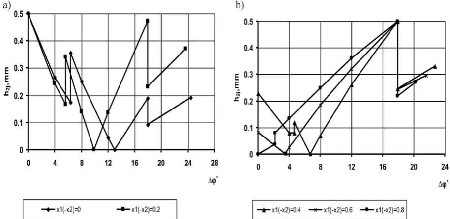
and pjhmax decreases or is maintained to the minimum (x1= −x2= 0.8).Figures 2 and 3 illustrate the linear wear of the gear
h
2j and the pinionh
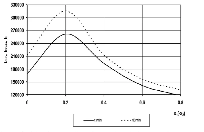
1j.The gear teeth are the first to reach the maxi-mum allowable wear at different characteristic points of tooth contact depending on the coeffi-cient of profile correction at the start of triple en-gagement or at the end of the double enen-gagement. Similar observations with respect to the points marking maximum wear can be made about the pinion teeth. Figure 4 illustrates the relationship between minimum gear durability and profile correction.
The maximum durability is exhibited by the gear with profile correction when x1= −x2 = 0.2 – its durability is higher by 1.55 times than that of the gear without profile correction.
To determine the effect of gear wheel width on the type of engagement and the above contact and tribological parameters, two types of heli-cal gear were tested: one described by the gear wheel width
b
W = 30 mm and double-single-double engagement, and the other described byW
b
= 54.275 mm and triple-double-triple engage-ment. Accordingly, Figure 5 shows the results of the maximum contact pressurep
jmaxfor the two tested width of gear wheels.de-Advances in Science and Technology Research Journal Vol. 13(1), 2019
56
Fig. 1. Variations in the initial contact pressures pjmax during the meshing of teeth due to wear a)
b)
Fig. 2. Linear wear of the gear teeth along their profile
57 crease (by 1.92 ÷ 1.8 times) in the initial
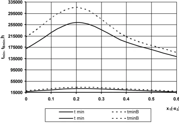
con-tact pressures at the start of the engagement zone and by 1.95 times at the place where the type of engagement changes. The minimum du-rability of the gear is significantly more affect-ed by the width of the gear wheels and the type of engagement, which is illustrated in Figure 6. In the case of the gear without profile correc-tion, the minimum gear durability increases by over 10 times, and when the optimal values of the correction coefficients are applied x1= −x2 = 0.2 – by 9.6 times.
CONCLUSIONS
1. We determined the optimal gear width in helical cylindrical gears which ensures that the length of the contact line is maintained constant. 2. Using a new method for the determination of
wear and durability of helical gears, depend-ing on the profile correction and the type of en-gagement, a numerical solution block method was proposed to the problem of determining the maximum contact pressures, linear wear of the teeth and durability of the gear.
Fig. 3. Linear wear of the pinion teeth along their profile
a) b)
Advances in Science and Technology Research Journal Vol. 13(1), 2019
58
Fig. 5. Maximum contact pressures (a) and their variations (b) due to tooth wear: bW = 30 mm (top), W
b = 54.275 mm (down)
Fig. 6. Profile correction versus minimum gear durability when
W
b = 54.275 mm (top), bW= 30 mm (down) a)
59 3. The study was performed on a helical gear
with optimized gear width ensuring a constant meshing force and on a helical gear with de-creased wheel width.
4. It has been found that the increase in the gear width in the range between 30 and 54.275 mm results in an almost proportionate decrease in the maximum contact pressures.
5. The increase in the gear width by 1.81 times leads to a significant increase in the mini-mum gear durability – by 10.24÷8 times, de-pending on the applied coefficients of profile correction.
REFERENCES
1. Drozdov Yu. To the development of calculation methods on friction wear and modeling. Wear
re-sistance. Science, Moscow, 1975.
2. Pronikov A. Reliability of machines. Mashi-nostroenie, Moscow, 1978.
3. Grib V. Solution of tribotechnical tasks with nu -merous methods. Science, Moscow, 1982.
4. Brauer J., Andersson S. Simulation of wear in gears with flank interference – a mixed FE and analytical
approach. Wear, (254), 2003, 1216-1232.
5. Flodin A., Andersson S. Simulation of mild wear in
spur gears. Wear, 1-2, (207), 1997, 16-23.
6. Flodin A., Andersson S. Wear simulation of spur gears. Tribotest J, 3 (5), 1999, 225-250.
7. Flodin A., Andersson S. Simulation of mild wear in
helical gears. Wear, 2 (241), 2000, 123-128. 8. Flodin A., Andersson S. A simplified model for
wear prediction in helical gears. Wear, 3–4 (249), 2001, 285-292.
9. Ulaga S. M., Ulbin M., Flasker J. Contact problems of gears using Overhauser splines. Int. J. Mech.
Sci, (42), 1999, 85-95.
10. Kahraman A., Bajpai P., Anderson N.Е. Influence of tooth profile deviations on helical gear wear. J.
Mech. Des., 4 (127), 2005, 656-663.
11. Pasta A., Mariotti Virzi G. Finite element method
analysis of a spur gear with a corrected profile. J. Strain Analysis, (42), 2007, 281-292.
12. Mekhalfa A., Bonaricha A., Kallouche A., Hadjadj
E. Teeth’s Gear Correction. J. Rev. of Mech. Ing.,
3, 2009, 271-274.
13. 13. Kolivand M., Kahraman A. An ease-off based
method for loaded tooth contact analysis of hypoid
gears having local and global surface deviations. J.
Mech. Des., 7 (132), 2010.
14. Zwolak J., Martyna М. Analiza naprężeń kontak
-towych i naprężeń zginających występujących w przekładniach zębatych power shift. Tribologia, 3 (42), 2011, 155-165.
15. Zwolak J., Wittek M. Optymalizacja parametrów
geometrycznych kół zębatych w aspekcie mini
-malizacji naprężeń kontaktowych. Tribologia, 6
(45), 2011, 283-291.
16. Chernets M.V., Yarema R.Ya., Chernets Yu.M. A
method for the evaluation of the influence of cor -rection and wear of the teeth of a cylindrical gear
on its durability and strength. Part 1. Service live and wear. Materials Science, 3, 2012, 289-300.
17. Chernets M.V., Yarema R.Ya., Chernets Yu.M.
A method for the evaluation of the influence of
correction and wear of the teeth of a cylindrical gear on its durability and strength. Part 2. Contact
strength. Materials Science, 6, 2012, 752-756. 18. Chernets M., Kiełbiński J., Chernets Yu. A study on
the impact of teeth meshing conditions and profile
correction on the cappying capacity, wear and life of a cylindrical gear. Tribologia, 2, 2016, 25-43. 19. Czerniec M. The accuracy of an accelerated
meth-od for the evaluation of life of cylindrical gears
with profile correction. Applied Computer Science,