361
Fuzzy Controlled Shunt Active Used For Minimization of Total
Harmonic Distortion of Transmission Line
Pankaj Agnihotri1, Manish Awasthi2, A.B.Sarkar3
Electrical and Electronics Engineering1, 2, 3 1, 2 Jawaharlal Nehru College of Technology, Rewa
3Govt. Engineering College Rewa
1pankajk.agnihotri@gmail.com, 2manishawa08@gmail.com, 3ab.sarkar@gmail.com
Abstract:- When using nonlinear loads, affects the
quality of supply power ,which leads to a number of issues like harmonics, voltage sag, voltage swell, flicker, voltage imbalance etc. These issues affect the performance and the lifetime of the utilities. In order to overcome issues arises due to nonlinear loads power filters were developed. This work proposed an active filter which is controlled by PI controller and Fuzzy logic controller to reduce the THD (total harmonic distortion). Here we compared the results of active filter results, without controller and with PI and Fuzzy controller. Results show that performance of fuzzy controller is better than PI controller.
Keywords: - Harmonic reduction, Active filter, PI
controller, Fuzzy logic controller.
I. INTRODUCTION
In recent years, the increasing use of power electronics in the commercial and industry processes results in harmonics injection and lower power factor to the electric power system [16]. Conventionally, in order to overcome these problems, passive R-L-C filters have been used. The use of this kind of filters has several disadvantages. Recently, due to the evolution in modern
power electronics, new device called “shunt active power filter (SAPF)” was investigated and recognized as
a viable alternative to the passive filters. The principle operation of the SAPF is the generation of the appropriate current harmonics required by the non-linear load. In fact active filters do not present all the typical drawbacks of passive systems such as the detuning of single tuned filters due to changes of system operative conditions and surrounding environment or the generation of resonance at particular frequencies, between the network and filter reactance, that amplifies unwanted harmonics. Active power filters are more and more capturing the interest of researchers and industries owing to the decreasing quality of power supplied by the electrical distribution companies and the difficulties in fulfilling the constraints imposed by national and international standards only by using
362
proportional plus integral (PI) controller for the generation of a reference current template. In recent times, fuzzy logic controller has generated a great deal of interest in various applications and has been introduced in the power electronics field [8]-[10]. The advantages of fuzzy logic controllers over the conventional PI controller are that they do not need an accurate mathematical model; they can work with imprecise inputs, can handle nonlinearity, and may be more robust than the conventional PI controller. Use of fuzzy logic for minimization of harmonics and improvement of power quality is not a new issue rather various authors have introduced some innovative methodologies using these tools [11]. The most important observation from the work reported by various researchers for power quality improvement is the design of active power filter under
‘fixed load’ conditions or for loads with slow and small
variation [12]. In this chapter a fuzzy logic controlled SAPF for current harmonics elimination is presented. The control scheme is based on two FLCs, the first one controls the dc bus voltage and the second one controls the output current of the inverter.
II. The Active Power Filter
When linear loads are connected to the supply the waveforms are linear. Whereas non linear loads are connected harmonic appears on electric voltage or current. The harmonics are integer multiples of system frequency. This leads to various power quality problems like heating of the devices, mis-triggering of the drives, pulsating output in the motors, etc., a harmonic filter are used to eliminate the harmonics. There are three basic types of harmonics filters given below.
2.1 Passive power filters
It is a type of filter, which consists of only passive components. It consists of linear elements like resistors, capacitors and inductors. They are also called as LC filters, which produce series resonance or parallel resonance that forms a major drawback of this type of filter. Another drawback of PPF is the cost which increases as the voltage rating of the inductor and capacitor increases.
2.2 Active Power Filter
APF is a type of filter that uses either current or voltage source as its major component. They compensate voltage or current harmonics by injecting the negative of the harmonic signal measured injected signals fed are of same magnitude but in phase opposition with the measured harmonic signals [12]. It is controlled to
draw/supply a compensated current from/to the utility, such that it eliminates reactive and harmonic currents of the non-linear load. Thus, the resulting total current drawn from the ac mains is sinusoidal. Ideally, the APF needs to generate just enough reactive and harmonic current to compensate the non-linear loads in the line.
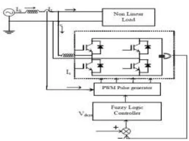
Figure1 Active power filter connected with transmission line
III. Active Filter Control Scheme
3. 1 PI Control Scheme
Figure 2 shows the active power filter compensation system with PI control scheme. In order to implement the control algorithm of a shunt active power filter, the DC capacitor voltage (Vdc ) is sensed and compared with
the reference value (Vdcref ). The Input of PI controller is
the value of Error, e = Vdcref− Vdc , and its output, after a
limit, is considered as the magnitude of peak reference current max I . The switching signal for the PWM converter are obtained from comparing the actual source currents ( isa , isb ,isc ) with the reference current templates ( Isa Isb Isc ) in a hysteresis current controller. The output pulses are applied to the switching devices of the PWM converter [14]. Since coefficients of PI controller, Kp and Ki, are fixed in this model, the
performance of active power filter under random load
variation conditions is not as well as ‘fixed load’
condition. To overcome this problem and make a robust controller, a fuzzy logic controller is designed to tune Kp and Ki on the base of load current value.
3.2 Fuzzy Logic Controller (FLC)
363
expert knowledge. FLC has a fixed set of control rules,
usually derived from expert’s knowledge. The
membership function (MF) of the associated input and output linguistic variables is generally predefined on a common universe of discourse. For the successful design
of FLC’s proper selection of input and output scaling
factors (gains) or tuning of the other controller parameters are crucial jobs, which in many cases are done through trial and error to achieve the best possible control performance.
Fig. 2 a) Active filter system b) Active filter system using PI controller
3.2.1 Structure of Fuzzy Controller
The basic structure of fuzzy controller is shown in fig 3,
Fig 3 Blocks of a fuzzy controller
A fuzzification interface, the fuzzy control initially converts the crisp error and its rate of change in displacement into fuzzy variables; then they are mapped into linguistic labels. Membership functions are defined within the normalized range (-1, 1), and associated with each label.
IV. SIMULINK MODEL FOR ACTIVE POWER FILTER USING FUZZY CONTROLLER
Fig. 4 shows the block diagram of PI/Fuzzy controller used for the controlling of active power filter. The simulation is done using MATLAB for the fuzzy logic controlled voltage source PWM rectifier. The complete rectifier system is composed of mainly (1) three phase source, (2) voltage source PWM rectifier, (3) fuzzy controller, and (4) hysteresis controller.
Fig. 4 Block Diagram of Fuzzy controlled improved power quality converter
Fig. 5. Simulated power circuit without controlled improved power quality converter
Fig. 6. Simulated power circuit for PI controlled improved power quality converter
364 V. SIMULATION RESULTS
The current and voltage waveform of the conventional three phase rectifier without controller is shown in fig 7. The current waveform for one cycle and its harmonica spectrum is shown in fig 8 (a) & (b). The current is non sinusoidal and total harmonica distortion (THD) is very high (88.84%). To make the current sinusoidal and THD within permissible limit current controller is used.
Fig. 8 Waveform without controller
Fig. 9 Harmonics spectrum without controller
Fig. 10 Harmonics spectrum with PI controller
Fig. 11 Harmonics spectrum with Fuzzy controller Table 1: Comparative Analysis of THD by Using Various
Controllers
VI. CONCLUSION
Based on the simulation results, it can be concluded that, fuzzy logic controlled PWM rectifier perform satisfactory for the compensation of line current. After compensation, line current become sinusoidal, balanced and in phase with the respective source voltage and reduces the THD of the source current below 5% limit. It is clear from simulation result that the transient performance of the source current and DC side capacitor voltage is better for the fuzzy controller compared to the PI controller in term of the setting time and % rise/fall in DC link voltage. The steady state performance of the fuzzy controller is comparable with that of PI controller.
REFERENCES
[1]. G.K. Singh, A.K. Singh, R. Mitra., “a simple fuzzy logic
based robust active power filter for harmonics minimization under random load variation” Electr.
Power Syst. Res., 2006.
[2]. B. S., Malesani L., Mattavelli P., IEEE Trans. on Ind. Electron. Vol. 45,722-729, 1998.
[3]. W. M. Grady, M. J. Samotyj, and A. H. Noyola, “Survey
of active power line conditioning methodologies,”
IEEE Trans. Power Del., vol. 5,no. 3, PP. 1536-1542, Jul. 1990.
[4]. V. E. Wagner, J.c. Balda, D. C. Griffith, A. McEachern, T. M. Barnes, D.P. Hartmann, D.J. Philleggi, A.E. Emannuel, W.F. Hortion, W.E. Reid, R.J. Ferraro, W.T.
0 0.05 0.1 0.15 0.2 0.25 0.3
-20 0 20
Selected signal: 15 cycles. FFT window (in red): 2 cycles
Time (s)
0 10 20 30 40 50
0 0.05 0.1 0.15 0.2 0.25 0.3
Harmonic order Fundamental (50Hz) = 29.66 , THD= 1.60%
M
ag
(
%
o
f
F
un
da
m
en
ta
365
Jewell, Effects of harmonics on equipment’s, IEEE Trans. Power Deliv. 8 (2) (1993) 672-680.
[5]. B. Singh, A. Chandra, and K. Al-Haddad, “Computer -aided modeling and simulation of active power
filters,” Elect. Mach. Power Syst., vol. 27, pp. 1227 -1241, 1999.
[6]. K. Chatterjee, B. G. Fernandes, and G. K. dubey, “An
instantaneous reactive volt-ampere compensator and
harmonic suppressor system,” IEEE Trans. Power
Electron. vol. 14, no. 2, pp. 381-392, Mar. 1999.
[7]. S. Jain, P. Agarwal, and H. O. Gupta, “Design
simulation and experimental investigations on a shunt active power filter for harmonics and reactive
power compensation,” Elect. Power Compon. Syst.,
vol.32, no. 7, pp. 671-692, Jul. 2003.
[8]. B. K. Bose, Expert Systems, Fuzzy Logic and Neural Network Application in Power Electronics and Motion Control. Piscataway, NJ: IEEE Press, 1999. [9]. V. S. C. Raviraj and P. C. Sen, “Comparative study of
proportional integral, sliding mode, and fuzzy logic controllers for power converters, ”IEEE Trans. Ind. Appl., vol. 33, no. 2, pp. 518-524, Mar./Apr. 1997. [10]. Dell’ Aquila, A. Lecci, and V. G. Monopoli, “Fuzzy
controlled active filter driven by an innovative
current reference for cost reduction,” in proc. IEEE Int. symp. Ind. Electron. vol. 3, May 26-29, 2002. [11].J. A. Momoh, X.W. Ma, K. Tomsovic, Overview and
Literature survey of fuzzy set theory in power systems, IEEE Trans. Power Syst. 10, 1995.
[12]. G.K. Singh, A.K. Singh, R. Mitra., “a simple fuzzy logic
based robust active power filter for harmonics
minimization under random load variation” Electr.
Power Syst. Res. (2006).
[13].Recommended Practices and Requirements for Harmonic Control in Electronic Power Systems, IEEE Standard 519-1992, New York, 1993.
[14].C. N. Bhende, S. Mishra, and S. K. Jain, “TS -Fuzzy-Controlled Active Power Filter for Load
Compensation”, IEEE Transactions on Power
Delivery, Vol. 21, No. 3, July. 2006.
[15].A. Elmitwally, S. Abdelkader, M. Elkateb
“Performance evaluation of fuzzy controlled three
and four wireshunt active power conditioners” IEEE
Power Engineering Society Winter Meeting, Volume 3, Issue, 23-27 Jan 2000 PP. 1650 – 1655 2000.