U-slot Loaded Rectangular Patch Antenna for Dual Band Operation
Amel Boufrioua
Electronics Department, Technological Sciences Faculty University Constantine 1, Ain El Bey Road, 25000 Constantine, Algeria
boufrioua_amel@yahoo.fr
ABSTRACT: In this paper, a dual frequency resonance antenna is analysed by introducing U-shaped slot in a rectangular
patch, the results in terms of return loss and radiation pattern are given. It is observed that various antenna parameters are obtained as a function of frequency for different value of slot length and width; it is easy to adjust the upper and the lower band by varying these different antenna parameters. In the present work variation of substrate permittivity is also studied. All the theoretical results using Matlab are compared with the simulated results obtained from Ansoft HFSS which are in close agreement.
Keywords: U-shaped, Slot, Rectangular, Patch, Antenna, Dual Band
Received: 10 September 2013, Revised 17 October 2013, Accepted 23 October 2013
© 2013 DLINE. All rights reserved 1. Introduction
Today, the state of the art antenna technology allows the use of different types and models of antennas,depending on the area of application considered. Microstrip antennas are now extensively used in various communication systems due to their compactness, economical efficiency, light weight, low profile and conformability to any structure. However, microstrip patch antenna is limited by its inherent narrow bandwidth. Therefore, this problem has been addressed by researchers and many configurations have been proposed for bandwidth enhancement [1-3]. Several patch designs with single feed, dual frequency operation have been proposed recently [4-7]. When a microstrip patch antenna is loaded with reactive elements such as slots, stubs or shorting pin, it gives tunable or dual frequency antenna characteristics [5]. A rigorous solution to the problem of a rectangular microstrip antenna which is the most widely used configuration because its shape readily allows theoretical analysis [8]. Also it is found that the substrate permittivity is a very important factor to be determined in microstrip antenna designs [9]. In this paper, a rectangular microstrip patch antenna with U-shaped slot is presented. The proposed antenna can completely cover two bands. The proposed antenna provides a significant size reduction. Dual frequency is tuned by changing the dimensions of the slot. In this paper the simulation resultants and the performance analyses using Matlab, and Ansoft HFSS software of the proposed rectangular microstrip patch antenna with U–shaped slot is presented, different parametric studies have allows and the effect of the various antenna parameters on the return loss and the radiation of the proposed antenna are given.
2. Antenna design
Figure 1. Geometry of U-shaped slot loaded rectangular patch antenna
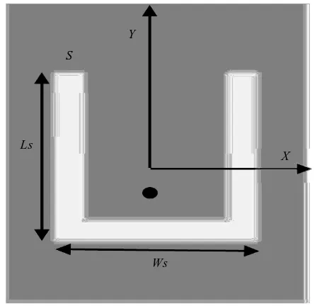
Figure 2. Dimensions of U-shaped slot in a rectangular patch 3. Results and Discussion
In this study we simulated U-shaped slot loaded rectangular patch antenna using the Ansoft HFSS software and Matlab code. Table 1 shows the different parameters of this proposed rectangular microstrip patch antenna with U–shaped slot with εr = 2. The folowing figures show the variation of return loss S11 with frequency and the effect of the different physical parameters on the return loss S11, the resonant frequencies and the band widths of the proposed U-shaped slod loaded rectangular patch antenna.
Radiating conductor
Y
X
Z L
W
Ground plane
h
Ws Ls
S
Y
X
the dielectric material is assumed to be nonmagnetic with permeability µ0. The patch is fed by a probe coaxial (50Ω).
The U-shaped slot with dimension (Ls, Ws ) is embedded in the rectangular patch, (see Figure 2). Feeding is accomplished with a probe coaxial located on the axial of symmetry of the antenna in the point of coordinates x0 and y0.
Figure 3. Variation of return loss S11 with frequency obtained from Matlab code
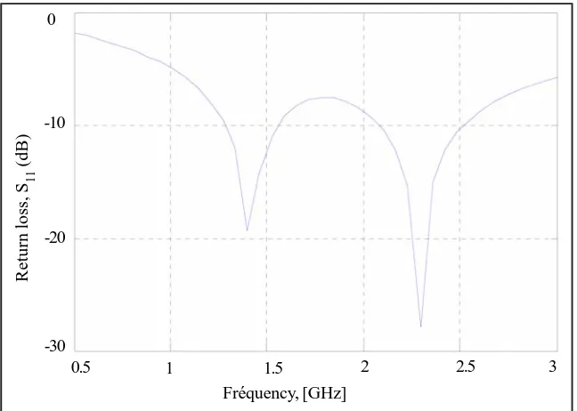
Figure 4. Variation of return loss S11 with frequency obtained from Ansoft HFSS software
Parameters W d1 h S Ls Wn Wb Ws Value (mm) 70 50 15 1 32 15 (0,−14.95) 5 40
Table 1. Design parameters of the U-shaped slot in a rectangular patch antenna
From Figure 3 given by Matlab it is clear that the antenna resonate at two frequencies (Fr1=1.4GHz and Fr2 = 2.285GHz) with two band widths. The −0dB bandwidth of lower and upper resonance frequency is respectively 21,42 % and 17,5 %. From Figure 4 given by Ansoft HFSS, the antenna resonate at two frequencies (Fr1 =1.32GHz and Fr2 = 2.31GHz) with two band widths. The −10dB bandwidth of lower and upper resonance frequency is respectively 7,57 % and 17,3 %.
0
-10
-20
-30
0.5 1 1.5 2 2.5 3
Return Loss Patch_Antenna_ADKv1 0.00
−5.00
−10.00
−15.00
−20.00
−25.00
1.00 1.25 1.50 1.75 2.00 2.25 2.50 2.75 3.00
−30.00
1,
Return loss, S
11
(dB)
Fréquency, [GHz]
dB (St (1,1))
Fréq [GHz]
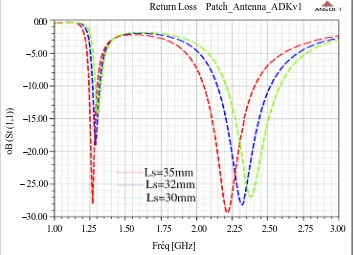
Figure 5. Variation of return loss S11 with frequency obtained from Matlab code for different value of slot length Ls
Figure 6. Variation of return loss S11 with frequency obtained from Ansoft HFSS software for different value of slot length Ls The variation of return loss S11 according to Ls is shown by Figure 5 obtained from Matlab code, it is observed that the increase of the Ls, decreases both the lower and the upper resonance frequencies. In Figure 6 obtained from Ansoft HFSS software. It is found that the variation of the upper resonance frequencies is more significant than the lower resonance.
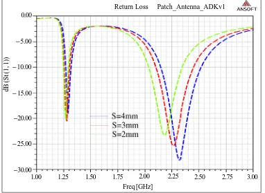
For the variation of S11 according to slot width S shown by Figure 7 (obtained from Matlab code) and Figure 8 (obtained from Ansoft HFSS softaware), it is observed that the upper gap of the resonance frequencies increase with increasing value of the slot width. It can be seen clearly that the slot width S has a stronger effect on the upper resonance frequencies than the lower resonant frequencies.
Return loss, S
11
(dB)
0
−10
−20
−30
0.5 1 1.5 2 2.5 3
Return Loss Patch_Antenna_ADKv1
oB (St (1,1))
0.00
−5.00
−10.00
−15.00
−20.00
− 25.00
−30.00
1.25 1.50 1.75 2.00 2.25 2.50 2.75 3.00
1.00
Fréquencey, [GHz] Ls = 35mm
Ls = 30mm Ls = 32mm
Figure 7.Variation of return loss S11 with frequency obtained from Matlab code for different value of slot width S
Figure 8. Variation of return loss S11 with frequency obtained from software for different value of slot width S
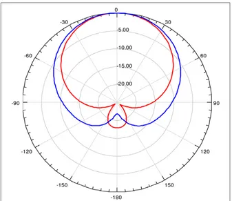
All theoretical results using Matlab are found to be approximately in good agreement with the simulated results obtained with Ansoft HFSS software and with [4]. Radiation pattern of the antenna is shown in Figure 9 and 10 for both upper and lower resonance in both principal planes E and H.
Return loss, S
11
(dB)
0
−10
−20
−30
0.5 1 1.5 2 2.5 3
Return Loss Patch_Antenna_ADKv1 0.00
− 5.00
− 10.00
− 15.00
−20.00
− 25.00
−30.00
1.00 1.25 1.50 1.75 2.00 2.25 2.50 2.75 3.00
dB (St (1, 1))
Figure 9. Radiation pattern of U-shaped slot loaded rectangular patch antenna for both upper resonant frequency (red line) and lower resonant frequency (blue line) at H plane
4. Conclusion
The U-shaped slot loaded rectangular patch has been treated in this paper, it is found that this structure can operate at two resonance frequencies and consequently this antenna can be used for dual band operation, also the effects of different physical parameters on the characteristics of this structure are investigated, also the variation of substrate permittivity is presented.
Numerical results indicate that both the upper and lower resonant frequencies and the band widths depend on the size of the slot dimensions. Also the radiation pattern of both upper and lower resonant frequency of the proposed antenna is presented in the principal planes E and H.
References
[1] Alexopoulos N. G, Jackson D. R. (1987). Fundamental superstrate (cover) effects on printed circuit antennas. IEEE Trans. Antennas Propagat, 32, p. 807–815.
[2] Meshram, M. K., Vishvakarma, B. R. (2001). Gap-coupled microstrip array antenna for wide-band operation. International Journal of Electronics, 88, p. 1161-1175.
[3] Row, J-S, Wong, K. L. (1993). Resonance in a superstrate-loaded rectangular microstrip structure. IEEE Trans. Antennas Propagat, 29, p. 1349–1355.
[4] Ansari, J A., Dubey, S. K., Singh, P., Khan, R. U., Vishvakarma, B. R. (2008). Analysis of Uslot loaded patch for dualband operation. International Journal of Microwave and Optical Technology, 3, p. 80-84.
[5] Ansari, J. A., Mishra, A. (2011). Half U-slot loaded semicircular disk patch antenna for GSM mobile phone and optical communications. Progress In: Electromagnetics Research C, 18, p. 31-45.
[6] Srivastava, D. K., Saini, J. P., Chauhan, D. S. (2009). Broadband stacked H-shaped patch antenna. International Journal of Recent Trends in Engineering, 2, p. 385-389.
[7] Wang, E., Zheng, J. (2009). A novel dual-band patch antenna for WLAN communication. Progress In Electromagnetics Research C, 6, p. 93-102.
[8] Boufrioua, A., Benghalia, A. (2006). Effects of the resistive patch and the uniaxial anisotropic substrate on the resonant frequency and the scattering radar cross section of a rectangular microstrip antenna. AST Aerospace Science and Technology, 10, p. 217-221.
[9] Boufrioua, A. (2009). Resistive rectangular patch antenna with uniaxial substrate. Chapter 6 in Antennas: Parameters, Models and Applications. Editor: Albert I. Ferrero, Nova Publishers, Inc. New York, p. 163-190.