Abstract— Shear walls are the structural members which are known to resist the lateral loads such as wind and earthquake etc. The main function of shear wall is to improve the lateral resistant of structure. This journal presents analysis results of twenty storeyed square-shaped RC building situated in seismic zone-4. Structural members are designed according to ACI code 318-99. The proposed building is analyzed by using ETABS software. Dead loads, superimposed dead loads, live loads, wind loads and earthquake loads are considered based on UBC-97. The present study deals with the structural performance of RC building with shear walls at different locations. The building is analyzed with considerations with five different locations of shear walls. Shear walls are placed at opposite corner, at opposite core, at center of periphery, at center of building along y-direction, and at core (Flange Type section). The objective of this study is to investigate the effectiveness of shear wall locations. The analysis is compared for its parameters such as storey drift, maximum displacement, storey shear and storey moment. Lateral stiffness of the proposed building without shear wall are compared to those with six different locations of shear walls. Structural stability checking such as overturning moment, drift limits, torsional irregularity and P-∆ effect are carried out.
Index Terms—, Storey drift, Storey moment, Storey shear, Shear wall.
1) INTRODUCTION
An earthquake is the sudden release of energy, caused due to collision of tectonic plates, eruption of molten magma from the earth’s crust and it may also occur due to the continuous vibrations generated by the heavy machinery equipment. Earthquake leads to the dislocation of the earth’s layer. Earthquakes have become a frequent eventall over the world. It is not easy to predict the intensity, location, and time of occurrence of earthquake. Looking at the past records of earthquake, there is increased in the demand of earthquake resisting building which can be fulfilled by providing the shear wall systems in the building.
Manuscript received October, 2018.
Thae Su Mon, Department of Civil Engineering, Pyay Technological University, Ministry of Education, Pyay, Myanmar, Phone/ +959794477998 (e-mail: [email protected]).
Min Zaw, Department of Civil Engineering, Technological
University(Magway), Ministry of Education, Magway, Myanmar, Phone/ +959795576311 (e-mail: [email protected]).
Myanmar is situated in a secondary seismic belt which is in the junction of two major belts called Alps-Himalaya and Circurm Pacific belts. Consequently, buildings areneededto withstand seismic effects and the structural design with safety and economy.
The decision regarding provision of shear wall to resist lateral forces play most important role in choosing the appropriate structural system for given project. Generally structures are subjected to two types of loads i.e. Static and Dynamic. Static loads are constant while dynamic loads are varying with time. This concept extended to concrete frames. The various aspects such as size and shape of building, location of shear wall and bracing in building, distribution of mass, distribution of stiffness greatly affect the behaviors of structures.
In majority civil structures, only static loads are considered while dynamic loads are not calculated because the calculations are more complicated. This may cause disaster particularly during Earthquake due to seismic waves. By providing shear wall in multi-storied building shown in figure (1), it can be resisted seismic wave of earthquake. The loads are calculated by E-TABS software by providing shear walls at different parts of building. In this study, twenty-storeyed RC building is analyzed.
Figure (1). Components of RC building with shear wall
2) METHODOLOGY A. Numerical Analysis
(a) Data Preparations of RC building RC building consists of 20 stories. Shape of structure : Square Plan dimensions : 78ʹ-8′ʹ x 78ʹ-8′ʹ Span length : 19ʹ-8′ʹ
Type of occupancy : Residential (6 Units/Floor) Typical story height : 10 ft
Bottom story height : 12 ft Overall height : 202 ft
Comparative Study on Seismic Analysis of
20-Storeyed RC Building with Different Shear
Wall Locations
Thae Su Mon, Min Zaw
Slab thickness : 6-inches Wall thickness : 4.5-inches Location of structure : Seismic Zone 4 (b) Material Properties
The strength of a structure depends on the strength of the materials from which it is made.
Analysis property data,
Modulus of elasticity for concrete, Ec = 3372 ksi Poisson’s ratio, Ʋ = 0.2
Coefficient of thermal expansion = 5.5x10⁻⁶ in/in per degree F Design property data,
Concrete cylinder strength, fc′ = 3.5 ksi Bending reinforcement yield stress, Fy = 50 ksi (c) Loading Consideration
Earthquake and wind loads are used according to UBC-97[6].
(i) Dead Load,
4.5” thick brick wall = 50 psf Superimposed dead load = 25 psf Unit weight of concrete = 150 pcf (ii) Live Load,
Live load on roof = 20 psf Live load on bed room = 40 psf Live load on stair case = 100 psf Live load on landing area = 100 psf Live load on lift = 2 tons (iii) Wind Load,
Basic Wind velocity = 80 mph Exposure type = Type B Total height of building = 202 ft
Method used = Normal Force Method Windward coefficient = 0.8
Leeward coefficient = 0.5 Importance factor = 1.0 (iv) Earthquake Load,
Seismic zone = 4 Zone Factor, Z = 0.4 Soil Type = SD Seismic Source Type = B Near Source Factor, Na = 1.0 Near Source Factor, Nv = 1.0 Seismic Response Coefficient, Ca = 0.44 Na Seismic Response Coefficient, Cv = 0.64 Nv
Framing System = SMRF (Special Moment Resisting Frame System)
Response Modification Factor, R = 8.5 Importance Factor, I = 1.0 Building Period Coefficient, Ct = 0.03
(d) Member Sizes of Structure Beam size: 14 x 24 inches (Main) 10 x 12 inches (Secondary)
Table I: Column Sizes
Story Level Interior Columns Exterior Columns 16F to 20F 20 inches x20 inches 16 inches x 16 inches
11F to 15F 26 inches x26 inches 20 inches x 20 inches 6F to 10F 32 inches x32 inches 26 inches x 26 inches 1F to 5F 36 inches x36 inches 30 inches x 30inches
Table II: Thickness of Shear Wall Story Level Thickness (inches)
16F to 20F 10
11F to 15F 12
6F to 10F 14
1F to 5F 16
B. Methods for Seismic Analysis of Buildings
(a) Equivalent Static Analysis (Linear static): It is the study of forces on building which represents the effect of earthquake motion at the ground level. In this method it is considered that the building has its own fundamental mode of response when the vibrations due to earthquake are generated.
(b) Response Spectrum Analysis (Dynamic Analysis): This method provides multiple modes of response of building during earthquake. The response of structure can be in any shape for each and every mode, responses read from the design spectrum based on the modal frequency and modal mass which in turn are combined to evaluate the total response of structure.
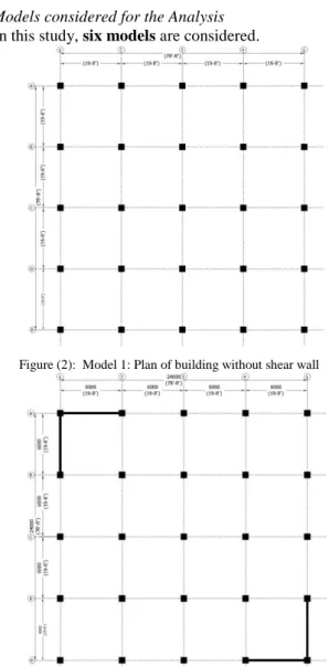
C. Models considered for the Analysis In this study, six models are considered.
Figure (2): Model 1: Plan of building without shear wall
Figure (3): Model 2: Plan of building with shear wall located at Opposite Corner (L-Shape or Flanged Shear Wall Type
Figure (4): Model 3: Plan of building with shear wall located at Opposite Core ( Plane Shear Wall Type)
Figure (5): Model 4: Plan of building with shear wall located at Center of Periphery ( Plane Shear Wall Type)
Figure (6): Model 5: Plan of building with shear wall located at the Center of building along the Y-Direction ( Plane Shear Wall Type)
Figure 2 to figure 7 show the plan of the proposed building without shear wall and with different locations of shear wall
Figure (7): Model 6: Plan of building with shear wall located at the Core (Flanged Type Section)
3) COMPARISONS FOR ANALYSIS RESULTS A. Comparison of Storey Drift in X-Direction
Comparison of storey drift in x-direction is shown in figure (8).
Figure (8): Storey Drift in X-Direction for Dynamic Analysis (inches)
It is found that the storey drifts in x-direction for Models 2, 3, 4, 5 and 6 can be reduced 67.71%, 85.42%, 77.08%, 25.52% and 79.17% respectively than the model without shear wall.
B. Comparison of Storey Drift in Y-Direction
Comparison of storey drift in y-direction is shown in figure (9).
It is found that the storey drifts in y-direction for Models 2, 3, 4, 5 and 6 can be reduced 50.77%, 63.85%, 86.15% and 78.46% respectively than the model without shear wall. On the other hand, it is found that Model 3 can be prominently increased 7.67% than Model 1 because of its shear wall location.
Figure (9): Storey Drift in Y-Direction for Dynamic Analysis (inches)
C. Comparison of Lateral Displacement in X-Direction Comparison of lateral displacement in x-direction is shown in figure (10).
It can be seen that the lateral displacement in x-direction for Models 2, 3, 4 and 6 can be reduced 41.15%, 72.05%, 57.48% and 62.36% respectively than the model without shear wall. On the other hand, it is found that those for Models 5 may be prominently increased 5.37% than Model 1 because of their shear wall locations.
Figure (10): Lateral Displacement in X-Direction for Dynamic Analysis (inches)
D. Comparison of Lateral Displacement in Y-Direction Comparison of lateral displacement in y-direction is shown in figure (11).
Figure (11): Lateral Displacement in Y-Direction for Dynamic Analysis (inches)
It can be seen that the lateral displacement in y-direction for Models 2, 4, 5 and 6 can be reduced 37.48%, 49.46%, 87.41% and 75.67% respectively than the model without shear wall. On the other hand, it is found that those for Model 3 may be prominently increased 11.15% than Model 1 because of its shear wall location.
E.Comparison of Storey Shear in Both Directions
Comparison of storey shear in both x and y-directions is shown in figure (12).
From the analysis results, it is found that the maximum storey shear for each models can be at the base level. The storey shear in both x and y-directions for Models 2, 3, 4, 5 and 6 can be respectively increased 18.55%, 15.59%, 98.82%, 15.6% and 64.08% than Model 1
.
Figure (12): Storey Shear in Both Directions for Dynamic Analysis (kips)
E. Comparison of Storey Moment in Both Directions Comparison of storey moment in both x and y-directions is shown in figure (13).
Figure (13): Storey Moment in Both Directions for Dynamic Analysis (k-ft)
From the analysis results, it is found that the maximum storey moment for each models can be at the base level. The storey moment in both x and y-directions for Models 2, 3, 4, 5 and 6 can be respectively increased 18.52%, 15.57%, 98.73%, 15.59% and 64.02% than Model 1.
F. Comparison of Lateral Stiffness in X-Direction
Lateral stiffness of each floor level can be calculated from the following relation.
F = kd equation (1) Where, F = lateral force
k = lateral stiffness d = lateral displacement
Comparison of lateral stiffness in x- direction is shown in figure (14).
Maximum lateral stiffness in X-direction for Model 1, 2, 3, 4, 5 and 6 are 6903.92 k,19638.6 k, 47873 k, 54880.67 k, 7980.25 k and 45295.33 k respectively.
Figure (14): Lateral Stiffness in X-Direction for Dynamic Analysis (k/in)
G. Comparison of Lateral Stiffness in Y-Direction
Comparison of lateral stiffness in y-direction is shown in figure (15).
Figure (15): Lateral Stiffness in Y-Direction for Dynamic Analysis (k/in)
Maximum lateral stiffness in Y-direction for Model 1, 2, 3, 4, 5 and 6 are 6903.92 k, 19638.6 k, 7978.83 k, 54880.67 k, 47881.5 k and 45295.33 k respectively.
4) DISCUSSISONS
Storey Drift in x-direction for Models with shear wall in different locations can be prominently reduced as compared to without shear wall model except from Model 3. It is found that storey drift in x-direction of Model 6 can be reduced 35.48%, 9.09%, 72.03% and 33.33% respectively than those for Model 2, Model 4 and Model 5. Besides, these for Model
4 can be reduced 29.03% and 69.23% respectively than those for Model 2 and Model 5. According to the above results, Model 6 is the most effectiveness than the other models. And also, Model 4 has second more effective than the other models for comparing the storey drift in x-direction.
Storey Drift in y-direction for Models with shear wall in different locations can be prominently reduced as compared to Model 1. It is found that storey drift in y-direction of Model 6 can be reduced 56.25%, 80% and 40.43% respectively than those for Model 2, Model 3 and Model 4. Besides, these for Model 4 can be reduced 26.56% and 66.43% respectively than those for Model 2 and Model 3. According to the above results, Model 6 is the most effectiveness than the other models. And also, Model 4 has second more effective than the other models for comparing the storey drift in y-direction.
Lateral displacement in x-direction for Models with shear wall in different locations can be prominently reduced as compared to without shear wall model except from Model 3. It is found that lateral displacement in x-direction of Model 6 can be reduced 36.04%, 11.48% and 64.28% respectively than those for Model 2, Model 4 and Model 5. Besides, these for Model 4 can be reduced 27.75% and 59.65% respectively than those for Model 2 and Model 5. According to the above results, Model 6 is the most effectiveness than the other models except from Model 3. And also, Model 4 has second more effective than the other models for comparing the lateral displacement in x-direction.
Lateral displacement in y-direction for Models with shear wall in different locations can be prominently reduced as compared to Model 1. It is found that lateral displacement in y-direction of Model 6 can be reduced 61.09%, 78.11% and 51.87% respectively than those for Model 2, Model 3 and Model 4. Besides, these for Model 4 can be reduced 19.16% and 54.53% respectively than those for Model 2 and Model 3. In this case, the other Model 5 is more effective than Model 4. According to the above results, Model 6 is the most effectiveness than the other models except from Model 5 for comparing the lateral displacement in y-direction.
Storey Shear in both directions for Models 2, 3, 4, 5, 6 and 7 can be prominently increased in compared with Model 1. It is found that storey shear in both directions of Model 4 can be increased 67.71%, 72.01%, 71.98% and 21.17% respectively than those for Model 2, Model 3, Model 5 and Model 6. Besides, these for Model 6 can be increased 38.41%, 41.96% and 41.93% respectively than those for Models 2, 3 and 5. According to the above results, Model 4 is the most effectiveness than the other models. And also, Model 6 has second more effective than the other models for comparing the storey shear in both directions.
Storey moment in both directions for Models 2, 3, 4, 5 and 6 can be prominently increased in compared with Model 1. It is found that storey moment in both directions of Model 4 can be increased 67.67%, 71.96%, 71.93%, 21.16% and 62.11% respectively than those for Model 2, Model 3, Model 5 and Model 6. Besides, these for Model 6 can be increased 38.39%, 41.92% and 41.9% respectively than those for Models2, 3 and 5. According to the above results, Model 4 is the most effectiveness than the other models. And also, Model 6 has second more effective than the other models for comparing the storey moment in both directions.
Lateral Stiffness in X-direction for Models 2, 3, 4 and 6 can be prominently increased in compared with Model 1. Among them, Models 4 and 6 have more effective than the other Models. It is found that the lateral stiffness in X-direction for Model 4 may be lightly greater than those for Model 6. On the other hand, these for Model 5 are similarly equal to those for Model 1 because of their shear wall locations.
Lateral Stiffness in x-direction for Models 2, 4, 5 and 6 can be prominently increased in compared with Model 1. Among them, Model 6 has more effective than the other Models except from Model 5. On the other hand, these for Model 3 are similarly equal to those for Model 1 because of its shear wall location.
5) CONCLUSION
In this study, 20-storeyed RC building is considered to analyze the structural behaviors of proposed building without and with shear wall at different locations. In this study, total Six Models are analyzed.
Necessary checking such as overturning moment, storey drift, torsional irregularity and P-∆ effect are carried out for the stability of the superstructure. Results for all stability checking are satisfied.
The proposed building is analyzed with Dynamic Analysis. In this study, (i) storey drift, (ii) lateral displacement, (iii) storey shear, (iv)storey moment and (v) lateral stiffness of the proposed building without and with shear walls at different locations are compared.
The maximum storey displacement for all six Models is occurred at the top roof floor level of the building.
The maximum lateral stiffness for all six Models is occurred at the first storey level of the building.
The building with shear wall experienced more storey shear and storey moment than those of the without shear wall building.
By placing the shear wall in the proposed building, it is observed that storey drift and storey displacement can be prominently reduced.
By placing the shear wall in the proposed building, it is observed that the lateral stiffness can be prominently increased.
In this study, it can be observed that the structural performances for placing the equilibrium shear wall in both X and Y-directions are good and sufficient for seismic response perimeters. On the other hand, the structural behaviors for placing the shear wall in one direction only are similarly equal to those for without shear wall building or structure. Therefore, placing shear wall in one direction only gives no good structural performances for differential criterion.
In this study, Model 6 (Building with shear wall located at the Core such as Flanged Type Section) has more effective than the other Models for comparing storey drift, lateral displacement and lateral stiffness.
In this study, Model 4 (Building with shear wall located at the Center of Periphery) has more effective than the other Models for comparing storey shear and storey moment.
Finally, according to the analysis results and structural performances, it is found that Model 6 is the most effectiveness than the other Five Models in this study.
ACKNOWLEDGMENT
The author would like to thank Dr. Nyunt Soe, Rector of Pyay Technological University for his motivation, supports and guidance. The author would deeply like to acknowledge her supervisor, Dr. Min Zaw, Professor and Head, Civil Engineering Department, Technological University (Magway), for his valuable suggestions, encouragement, supervision, and findings. The author is particularly grateful to her teacher, Daw Phyu Phyu Lwin, Lecturer and Head, Civil Engineering Department, Pyay Technological University, for her advice and permission.
REFERENCES
[1] Arthur H. Nilson, David Darwin and Charles W. Dolan, “Design of Concrete Structures”, Fourteenth Edition.
[2] U Nyi Hla Nge, “REINFORCED CONCRETE DESIGN”
[3] Ray W. Clough, Professor of Civil Engineering, University of California, and Joseph Penzien , International Civil Engineering Consultants, Inc, “DYNAMICS OF STRUCTURES”, Third Edition [4] Anil K. Chopra, “DYNAMIC OF STRUCTURES”, Fourth Edition. [5] Anil Baral, “Seismic Analysis of RC Framed Building”, Vol. 4, Issue
5, May 2015, pp. 2347-6710. [6] Uniform Building Code 1997
[7] Building Code Requirements for Structural Concrete (ACI 318-99) and Commentary
[8] “ETABS version (9.7.1)”, Computer & Structure Inc.
Thae Su Mon holds her BE (Civil) Degree from Technological University (Hinthada), Hinthada, Myanmar in 2006. After that, she worked at the Department of Civil Engineering, Technological University (Hpa-an) from 2007 to 2009. She has been currently working as a Lecturer at the Department of Civil Engineering, Pyay Technological University from 2010 to until now. She is also now attending to Master Degree at Pyay Technological University. Her research field is in the Structural Engineering. Min Zaw holds his BE (Civil) Degree from Mandalay Technological University, Mandalay, Myanmar in 2003. He also holds his ME (Civil) Degree from Yangon Technological University, Yangon, Myanmar in 2004. He also finished his Ph.D (Civil) Degree from Mandalay Technological University, Mandalay, Myanmar in 2008. After that, he worked at the Department of Civil Engineering, Technological University (Mawlamyaing). He also worked at the Department of Civil Engineering, Technological University (Hmawbi) from 2010 to 2017. He has been currently working as a Professor at the Department of Civil Engineering, Technological University (Magway). His research field is in the Structural Engineering.