Radboud Honours Academy 2011-12
May 29, 2012
Wilke Castelijns
Maria van Rooijen
David Venhoek
Patrick Uiterwijk
Quantum Cryptography
Preface
In this report we discuss the results of our project for the Radboud Honours Academy, concerning Quantum Key Distribution (QKD). We originally started this project with a much larger research subject in mind, namely quantum cryptography and quantum computers. At the beginning of this year, none of us had even heard of quantum cryp-tography. It was professor Klaas Landsman who introduced this as a research subject for the first year of the Honours programme. But after a short time, we felt that narrowing this subject was necessary: we decided to to forget about quantum computers and focus on currently commercially available systems implementing QKD protocols. In particular, our goal was to investigate the business versus the hacking culture. By exploring both the suppliers of quantum cryptographic devices and the people who want to hack these sys-tems, we wanted to get a complete and realistic a picture of the physical implementations of quantum cryptography that are nowadays possible.
The first part of our work consisted of theoretical research. We had to lay a mathe-matical foundation for our project and get a proper understanding of quantum mechanics and QKD protocols. We visited Serge Fehr at the CWI1 and Barbara Terhal at RWTH
(Aachen University). They answered our theoretical questions and helped us finding the right people for the remaining and most important part of our project, namely the phys-ical implementations of QKD and their weaknesses. During our trip to Z¨urich, we visited Normand Beaudry at the Eidgen¨ossische Technische Hochschule (ETH) Z¨urich, who al-ready told us a lot about QKD protocols used by the company ID Quantique and their physical implementations. The day after, we went to Geneva, where we visited ID Quan-tique and GAP-OpQuan-tique. At ID QuanQuan-tique, one of the few companies in the world that produce quantum cryptographic devices, Damien Stucki showed us their quantum key distribution products and explained how they work. At GAP-Optique, the Group of Ap-plied Physics at the University of Geneva, Nino Walenta showed us their lab and explained more about QKD protocols. To discover the weaknesses of the ID Quantique devices and learn more about possible attacks, we made a trip to Germany. In M¨unchen we visited the Ludwig-Maximilians-Universit¨at, where Sebastian Nauerth and his colleagues told us about free-space QKD and showed us many quantum cryptography related experiments. In Erlangen we visited Nitin Jain at the Max Planck Institute, who told us a lot about attacks on commercially available QKD systems. Finally, we contacted the famous ‘quan-tum hacker’ Vadim Makarov, who was very helpful in answering questions concerning the future of QKD. Unfortunately, we were not able to visit him (as we originally intended), since he recently moved from Trondheim to Waterloo in Canada.
After all these visits and extensive literature study, we think we are able to give a realistic overview of commercially available QKD systems and possible attacks exploiting their practical weaknesses, which we tried to do in this report.
In what follows we will first give a brief description of cryptography and quantum-cryptography. Also, we will give a short overview of the quantum-mechanic theory required for quantum cryptography. Subsequently we focus on commercially available proudct that implement quantum cryptography. In particular, we explore the gap be-tween their theoretical security and their practical vulnerability.
We would like to thank all the people we visited for giving us so much of their time and being almost as enthusiastic about our project as we were ourselves. We also want to thank the Radboud Honours Academy for giving us the opportinity to make our trips to Switzerland and Germany. Finally, we want to express our thanks to professor Klaas Landsman, who has been a great and involved supervisor throughout this year.
Contents
1 Introduction to cryptography 5 1.1 What is cryptography? . . . 5 1.2 Why cryptography? . . . 5 1.3 Types of cryptography . . . 5 1.4 Methods of cryptography . . . 6 1.4.1 Example: RSA . . . 71.5 The problem with classical cryptography . . . 7
2 A very brief introduction to quantum mechanics 9 2.1 States . . . 9
2.2 Superposition . . . 10
2.3 Measurements . . . 10
2.4 Combinations of systems . . . 11
2.5 Transformations . . . 12
3 Quantum key distribution protocols 13 3.1 Qubit based . . . 13
3.1.1 BB84 . . . 14
3.1.2 Ekert 91 . . . 14
3.1.3 SARG04 . . . 15
3.2 Continuum based . . . 15
3.2.1 Coherent one way . . . 15
4 Post-processing 17 4.1 Error correction . . . 17
4.2 Privacy amplification . . . 17
5 Proving security 19 5.1 Model . . . 19
5.2 Security of QKD in the model . . . 19
6 Commercially available products 21 6.1 ID Quantique SA . . . 21
6.2 Specifications of Clavis2 . . . . 22
6.2.2 Physical implementation . . . 24 7 Weaknesses of QKD devices 27 7.1 Preparation . . . 27 7.2 Channels . . . 28 7.3 Detection . . . 29 7.3.1 Avalanche photo-diodes . . . 29
7.3.2 Superconducting nanowire single photon detectors . . . 29
7.3.3 Faked states . . . 30
8 Possible attacks 31 8.1 Intercept-resend attacks . . . 31
8.1.1 Faked states attack . . . 31
8.1.2 Phase-remapping attack . . . 32
8.2 Photon number splitting attack . . . 33
8.3 Time-shift attack . . . 33
8.4 Quantum blinding . . . 35
8.4.1 Continuous-wave blinding . . . 35
8.4.2 Thermal blinding . . . 35
9 Summary and conclusion 37
10 Looking forward 39
Appendix A. Internal structure of Clavis2 41
Appendix B. Components of the physical implementation 43
Chapter 1
Introduction to cryptography
1.1
What is cryptography?
“Cryptography” is a word that comes from the contraction of the Greek wordsκρυπτ oς
(krypt´os) for “hidden”, andγραϕǫιυ´ (gr´afo) for “writing”. Literally translated, it says “hidden writing”, which describes the purpose of cryptography quite well: “writing”, or encoding, a piece of data or a text such that only the intended recipient can read the “clear text”, and anyone else gaining a copy of the “cipher text” has no clue of what it says, unless they have the required key to decrypt it.
1.2
Why cryptography?
There are many reasons why one would use cryptography. For example, in the case of submarines: communication between the submarine and the coast would have to be secured from the ears of the enemy, because otherwise the enemy would know exactly when and where a submarine would strike, and so they could intercept them.
Another, current, example is banking on the internet. If anyone would be able to eavesdrop on all data sent between you and your bank, they could empty your bank account.
1.3
Types of cryptography
Currently there are two main types of cryptography.
The first type of cryptography is symmetrical, or shared-key cryptography, where both parties have the same key that is used to both encrypt and decrypt the data. An example of this is the substitution cipher where you just rotate all letters by 13 positions in the alphabet. This means that if you use the same procedure twice on a text, you recover the original text.
The other, much more recent, type is asymmetrical-, or private-key cryptography, where each participant has a personal key pair consisting of a public and private key. The idea is that one can publish one’s public key, which everyone can subsequently use
to encrypt a message sent to him. But one would need the corresponding private key to decrypt the message, which only the key holder should possess.
The most popular type is symmetrical cryptography, since this requires only one key for both parties, instead of two public and two private keys. However, with symmetrical cryptography, one has the problem of key exchange. The problem is that one will need to share a big key with the other participant with whom one would like to communicate, but will need to agree on the used key securely, because if an eavesdropper learns the key, the participants still lose all secrecy of their messages. Currently, the standard solution for this is that one party generates the key, encrypts it asymmetrically with the public key of the other participant, and finally sends it to him. However, this also means that when the asymmetrical algorithm that has been used for the key exchange is broken, the shared key again becomes “public”.
1.4
Methods of cryptography
There are various ways to encrypt data, that each have their own advantages and disad-vantages. A scheme to encrypt data is called a “cipher”.
One of the first known and used ciphers is the “substitution cipher”, where one replaces each letter of the alphabet in the plaintext by a specific other letter to produce the ciphertext. Stipulating which letter is replaced by which provides the key for this cipher. An example could be to replace each letter by the next letter in the alphabet, so one would replacea by b, b byc, and so on. To decrypt, the receiver would have to replace each letter in the received text by the letter preceding it in the alphabet. This is a very simple cipher, and it can easily be broken if one just tries out all the possibilities (brute-forcing) of the substitution, or if one performs frequency analysis of letters in the ciphertext.
Since the previous procedure is a very easy method of encrypting data, it is also easy to break, and hence some adaptations have been invented that were a bit more secure. One such example is the Enigma cipher used by the Nazi’s, where each letter is still replaced by another letter in the alphabet, but the letter by which it gets replaced is not constant. This could be done because the Enigma used three or four rings which guide the electric signal produced by a press on a key on its keyboard to a specific letter in the end result, after which the rings turn a bit like a clock. This would be very hard to crack without having such a device, because one would need to know the configuration of the rings, as well as the initial position when the encryption started: frequency analysis would be impossible, because the letter that replaces another letter is not fixed. But brute-forcing combined with educated guesses is still an option, if one has enough ciphertext-examples, and this is indeed the way the Enigma cipher was broken during WWII.
A third way of “encrypting” data is called “steganography”, where one hides the data one wants to send inside other data, for example a movie or a picture. One way to do this is by just replacing the last bit of each byte in a picture by the next bit in the source document. If one would just look at a picture where steganography is used to hide a document, one would not notice too much difference, because those low bytes are only used for detailed color data. However, if one knows that the picture contains hidden data, one could retrieve it by extracting the last bits of each byte in the received picture.
One of the most basic digital ciphers is the one-time pad cipher, which works by executing the bit-wise XOR between the message you are trying to send and the key
stream. If you do not repeat the key-stream, this cipher is unbreakable for anyone not having the key.
But currently, we use ciphering schemes that are more complex, based on a mathe-matical function which takes the plaintext as argument, and gives the ciphertext as its result but which is practically impossible to invert. Some of the most often used such schemes are RSA, Rijndael (AES) and Diffie-Hellmann.
1.4.1
Example: RSA
We will give an example of a contemporary asymetrical encryption cipher, in the form of the RSA1 cipher, and explain what part of it is the most crucial.
In this example, Alice will create a key pair (Kpublic, Kprivate).
First, Alice randomly chooses two big prime numbers p and q. Then she needs to computen=p×q, which is one part of the public and private keys. Then she computes
φ(n) = (p−1)(q−1). Next, she needs a number e that has the following properties: 1 < e < φ(n) and gcd(e, φ(n)) = 1. Thise is very often a fixed number, for example, most software implementations just use e = 65.537, because it is harmless if a lot of people use the same value. Next, she calculatesd=e−1 modφ(n).
Now the public key of Alice is (n, e). This means that for someone to encrypt messages for Alice, one needs to know bothnande. Alice’s private key consists of (n, d). This is whyeis often called the encryption key, whereasdis called the decryption key, but both keys also needn, which is public.
Now, to encrypt a messagemfor Alice, Bob would calculate the ciphertextcwith the following formula: c=me modn.
Alice could decryptcto distill the original messagemby using the following formula:
m=cd modn.
As you can see from this example, the only secret part of the key isd, which is required for decrypting any messages sent. But to calculate the value ofd, one needs to have access toφ(n), or topandq(because from those two, you can calculated).
1.5
The problem with classical cryptography
The problem with all currently used algorithms, such as RSA, is that their security is based on the fact that reversing the process or brute-forcing it is “computationally hard”. This means that the sole reason they are deemed secure is that it requires very much calculation to retrieve the private key from the public key, or to retrieve the shared key from the eavesdropped communication.
In the case of RSA this lies in the fact that finding the prime factors of the public modulusnis deemed very hard since there are no known algorithms to efficiently factorize a big number.
The problem with this assumption is that, over time, computers get faster and faster, and as such also those computations do. This means that with a modern computer, it would cost (on average) over a thousand years to compute a 2048-bit private RSA key from a public key, but with a computer one can buy in two years, it may cost “just”
one hundred years. And when so-called quantum computers will be produced, those keys could perhaps be cracked in a few minutes.
This is where quantum cryptography comes in: quantum cryptography should be secure independently of this assumption. Almost paradoxically, then, quantum cryptog-raphy is a safeguard against possible future quantum computers!
So far, quantum cryptography mainly consists of Quantum Key Distribution (QKD), which exploits the laws of quantum mechanics to allow secure key exchange between two parties.
In principle, quantum key distribution is unconditionally secure, so that for the se-curity of the system it should be irrelevant to which devices and computing power any attacker has access. But here also comes the catch: in theory, quantum cryptography would guarantee perfect secrecy. But getting the devices as perfect as is needed for this purpose is very hard in practice. We have investigated whether or not they actually do guarantee this perfect secrecy, and if not: what is still wrong with them?
Chapter 2
A very brief introduction to
quantum mechanics
Quantum mechanics is the revolutionary theory that arose at the beginning of the 20th century to resolve fundamental problems of the physics of really small objects. For a more detailed description one can refer to any introductory textbook on quantum mechanics, such as the book by D.J. Griffiths.[11]
2.1
States
The basic element of quantum mechanics is a state. A state can be seen as a complete description of the system under consideration. For example, when looking at a photon in the case where we are only interested in its polarization, the state is specified by the direction of polarization. The collection of all possible states of the system under consideration is called its state space.
In quantum mechanics, the state space is embedded in a so-called Hilbert space, that is, in a complex vector space equipped with an inner product. In all cases that will be looked at in this report, this vector space turns out to be finite-dimensional. In the context of quantum mechanics, vectors are usually denoted by so-called kets|Ai, where
Ais some label. The inner product of such vectors|Aiand |Biis written as hA|Bi. A vector |Ai has unit length (i.e., is a unit vector), if hA|Ai = 1. Such vectors are very important in quantum mechanics, because states are mathematically described by unit vectors. However, it turns out that two states|Ciand |Diare physically equivalent, in that they represent the same physical situation, if and only if there is a complex numberγ
of absolute value|γ|= 1, such that|Ci=γ|Di. So, more precisely, quantum-mechanical states are unit vectors (in some Hilbert space), up to equivalence in the above sense. In particular, the overall phaseγ in a unit vector γ|Ai is physically irrelevant in so far as
2.2
Superposition
States may, of course, also be defined in classical mechanics (think, for example, of the position and momentum or velocity of a projectile). There is a very fundamental difference between classical and quantum-mechanical states, though. In classical physics there is no real way to combine two states into a new state (except probabilistically, as in statistical physics). In quantum mechanics, however, two states|Aiand|Bimay be combined (even in many different ways) into a new state called a superposition: this is a (complex) linear combination
α|Ai+β|Bi,
whereαandβare complex numbers that are arbitrary, except for the fact thatα|Ai+β|Bi
again needs to be a unit vector. For example, if|Aiand|Biare orthogonal, in the sense thathA|Bi= 0 (and, of course,hA|Ai=hB|Bi= 1), then
|α|2+|β|2= 1.
A simple example is α= cosφ andβ = sinφ, for some angleφ (between zero and 2π), giving a superposition
cosφ|Ai+ sinφ|Bi.
Another example, still assuminghA|Bi= 0, is (|Ai+δ|Bi)√2,
whereδis a single complex number of absolute value|δ|= 1. Parametrizingδ= exp(iφ) = cosφ+isinφ, the angle φis then called the relative phase between|Aiand |Bi. More generally, it follows from our earlier remark on the equivalence between|Aiandγ|Aithat, in a superpositionα|Ai+β|Bi, what matters physically is the relative phase between|Ai
and|Bi.
2.3
Measurements
All the above is just formalism: we also need to know how the concept of a state relates to what we can see in the real world. Here another (but closely related) difference between classical and quantum physics shows up. Classically, performing a measurement comes down to asking the system in which state it is, and getting the exact answer. If performed well, process is assumed to not alter the system under consideration.
Life is not so simple in quantum mechanics. During a measurement of a quantum state you take a collection of orthogonal states, which together span the entire state space (that is, an orthonormal base), and ask the system in which of these states it is. The result will always be exactly one of the states in that collection, and afterwards, if one measures again, one will always get the same result. This means that after the measurement, the system is in one of the states in the collection used to measure it, rather than in its original state. This remarkable fact is especially true if the system was originally in a superposition of several states in the collection defining the measurement, implying that a measurement on a quantum system disturbs that system. This fundamental property of
quantum mechanics is one of the cornerstones that make the amazing results of quantum cryptography possible.
We would also like to make predictions on the outcomes of a measurements. Remark-ably, the result of a measurement is to some extent random. We can, however, calculate the probability of each possible outcome. Suppose |Ai is the state of the system and
|Biis an element of the collection of states used for the measurement. The probability
P(B|A) that we get outcome|Bi in state|Aiis then given, through the inner product, by
P(B|A) =|hA|Bi|2.
To illustrate this formula, let us take a look at a photon, with degrees of freedom restricted to just polarization (hence forgetting its motion). This system has two orthogonal base states, which together generate the entire state space through superpositions. We have considerable freedom in choosing these base states. First, we may choose to use the base consisting of horizontal (linear) polarization (|Hi) and vertical (linear) polarization (|Vi). We can define relative angles for these by stating that the polarization angle of the horizontal state is zero by convention, angles increasing clockwise. The state of a photon with linear polarization angleφthen becomes
|φi= cosφ|Hi+ sinφ|Vi.
When we measure whether its polarization is horizontal (H) or vertical (V) in this state, according to the above formula the probability of each outcome is:
P(H|φ) = cos2φ;
P(V|φ) = sin2φ.
Another example is given by base states of circular polarization. Here a base is formed by states|0i′ and |πi′, which may be expressed in the previous base by
|0i′ = (|Hi+i|Vi)/√2;
|πi′ = (|Hi −i|Vi)/√2,
respectively. The state of a photon with phase angleϕthen becomes
|ϕi′= cos(φ/2)|0i′+ sin(φ/2)|πi′,
withφbetween 0 andπ. In that case, we obtain analogous formulae for the probabilities of the outcomes of the measurement with respect to the original set of states, like
P(H|ϕ′) = 1 2(cos 2(φ/2) + sin2(φ/2)) = 1 2; P(V|ϕ′) = 1 2(cos 2(φ/2) + sin2(φ/2)) = 1 2.
2.4
Combinations of systems
So far, we talked about single systems. However, in many cases we have a system that can be seen as the combination of multiple subsystems. It will be important for us to
translate the concepts introduced so far to combinations of systems. Suppose we have two systems, system 1 being in state|Ai and system 2 being in state |Bi. We say the combination of the two systems is in state
|Ai ⊗ |Bi,
called the tensor product of the two. The⊗operator is bilinear, meaning that (|Ai+|A′i)⊗ |Bi = (|Ai ⊗ |Bi) + (|A′i ⊗ |Bi) ;
|Ai ⊗(|Bi+|B′i) = (|Ai ⊗ |Bi) + (|Ai ⊗ |B′i).
The combination of the two systems can also be in states other than those that can be written as |Ai ⊗ |Bi. The theory also allows sums of those states, so that the system described above can also be in a state
(|A1i ⊗ |B1i) + (|A2i ⊗ |B2i),
up to normalisation (as a unit vector). In such a state it is not always possible to find two states|Aiand|Biof the subsystems such that the system is described as|Ai ⊗ |Bi. When this is impossible we call the two subsystems entangled.
2.5
Transformations
The last thing we need to look at is dynamics in quantum systems. We might want to perform some operations to the systems we are working with in quantum key distribu-tion, aside from measuring them. This is possible, but there are some limitations to the transformations we can apply in quantum theory.
First, they must be bijective, meaning that we must be able to undo the transforma-tion, given only the state after it has been applied. Second, the transformation must be linear: if it transforms|Aito |A′iand|Bito |B′i, then it transforms α|Ai+β|Biinto
α|A′i+β|B′i. The last condition is that it must preserve the inner product, in other
words,
hA|Bi=hA′|B′i.
The properties of the admissible transformations are jointly called unitarity.
Unitarity leads to a very important property of quantum mechanics, called the no-cloning theorem. Roughly speaking, this theorem states that it is impossible to clone, or duplicate, unknown quantum states. More precisely, there exists no unitary transfor-mation and no state |Bi of some (single) system such that, for arbitrary|Ai, the state
|Ai ⊗ |Biof the combined system consisting of two copies of the given system, is trans-formed to the new state|Ai ⊗ |Ai. Note that for some fixed state|Aione can certainly find a suitable state |Bi and a suitable unitary transformation that accomplishes the cloning|Ai ⊗ |Bi 7→ |Ai ⊗ |Ai; the point is that this is impossible for arbitrary|Ai(which is typically unknown).
Chapter 3
Quantum key distribution
protocols
In the rest of this paper we will focus on quantum key distribution. This is the secure exchange of secret keys over a public channel between two parties, potentially over long distances. First, we will discuss various protocols. This is then followed by an overview of how security proofs are structured and work.
In order to discuss its possible weaknesses we first need an understanding of how QKD works. For our research there are two important approaches to do this. One is based on the exchange of qubits. Algorithms in this class have usually been proven theoretically secure. The other approach is using so-called coherent states, and then using interference between pairs of pulses to detect eavesdropping. This approach has not yet been proven secure.
Any quantum key distribution protocol consists of two steps, which depending on the protocol and implementation are done either at the same time or one after the other. The first step consists of exchanging some random bits across a quantum channel. The second step consists of checking for errors in the exchanged sequence, correcting them and then shrinking the bit stream to compensate for all the information leaked to any potential adversaries. Here we will mainly discuss exchanging the bits across a quantum channel and the error detection, the other steps will be treated later on.
For all protocols discussed here there is a necessity for two channels. First and fore-most a quantum channel between the two parties, and then a classical and authenticated channel (meaning that Bob and Alice have a way of communicating knowing that the messages they get really come from the other party).
3.1
Qubit based
One of the approaches to QKD is using so-called qubits. These are systems with a state space spanned by two orthogonal states, conventionally called|0iand|1i. These states are normalized and orthogonal by definition. The communication is then done by exchanging a number of qubits between Alice and Bob.
Examples of physical systems which behave according to the model we have for qubits are photons, whose polarizations can be used as a qubit.
3.1.1
BB84
The first QKD protocol, based on qubits, was published by Charles Bennet and Gilles Brassard in 1984. The exchange is done by Alice preparing qubits in a specific state and Bob measuring them.
During the protocol Alice and Bob use two bases. The first is the base formed by
|0iand|1i. This is what we will call the computational base. The other is the so-called Hadamard base, which consists of|+i=√1
2(|0i+|1i) and|−i= 1
√
2(|0i − |1i). |+iwill
be interpreted as meaning 1 and|−iwill be interpreted as meaning 0.
First Alice preparesnqubits as follows. For each qubit she randomly chooses whether it will represent a 1 or a 0. For each qubit she then randomly chooses a base in which she will encode it. She then sends the qubits to Bob.
Bob chooses for each qubit a random base in which he will measure. He notes the outcome and base of each measurement. After he has done this he communicates with Alice over a public authenticated channel which qubits were measured in which base. Both parties then throw away all bits for which they did not use the same base.
A random subset of the remaining bits is then exchanged between Alice and Bob to determine the amount of bits eavesdropped. This works because if an eavesdropper measures in a different base than Bob does, she has a 50% chance of introducing an error in Bob’s result. This effectively means that for 25% of the bits eavesdropped Bob will get a different result from Alice, even though he measured in the same base.[2]
3.1.2
Ekert 91
An improvement on the BB84 protocol was published in 1991 by Artur Ekert. Instead of using two independent bases, it uses three bases for Alice, and three bases for Bob, with only a partial overlap between the set of bases used by Alice and that used by Bob. They usually are indicated by angles, where a base of angleθmeans the base consisting of sin(θ)|0i+ cos(θ)|1i and cos(θ)|0i −sin(θ)|1i. Alice then uses the bases 0◦, 45◦ and
90◦, whereas Bob uses 45◦, 90◦ and 135◦.
During the quantum bit exchange phase either Alice, Bob or a third party that is untrusted, produces so-called EPR-pairs. These are pairs of photons in the state
1
√
2(|0i|0i+|1i|1i). These have the special property that if Alice and Bob measure in
the same base, then no matter what that base is, their results will always be perfectly correlated.
One member of each pair is sent to Bob and the other to Alice. Both now choose a random base to measure their qubit in. After the qubit exchange phase they exchange the bases used. The bits they measured in the same base now provide the bits for the key, whilst those that have not been measured in the same base are used to calculate the divergence from the so-called Bell inequalities, which is in turn used to calculate the number of bits eavesdropped. The advantage of this is that it is not necessary to use bits that could also have been used for the key to calculate the number of bits eavesdropped. In this way, the amount of data available for a key is potentially raised.[5]
3.1.3
SARG04
SARG04 is another improvement over plain BB84. It uses the same states as used for BB84, but Alice, instead of sharing the base she used for the measurement, indicates that she prepared one of the four non-orthogonal pairs of states and Bob only says whether his measurement result was conclusive. Bob’s measurement was conclusive if it was orthogonal to one of the two states given by Alice. If this is the case, Bob knows that Alice cannot have sent that state, and since she sent one of two states, Bob knows she must have sent him the other. This leads to Alice and Bob now sharing a common peace of information, which can be used to construct a key.
The advantage given by this approach is that in practical implementations, it allows the implementation to still function over connections with higher losses than those tol-erable for BB84. In practice, this means that the maximum distance over which a key exchange is possible increases.[26]
3.2
Continuum based
The other approach to QKD uses coherent states. These are the quantum states that come out of a laser when it gives a single pulse. The energy put into the laser determines the average number of photons in such a pulse. However, the actual number of photons in the pulse when measured, is a random variable. This gives some interesting effects. Two pulses from such a laser can be made to interfere in an interferometer as long as the number of photons in each pulse is not measured, even when the average number of photons is smaller than zero, and a majority of the pulses is empty when measured. This can be used to exchange a key, whilst still having checks against eavesdropping. However, most of these schemes have not yet been proven theoretically secure.
3.2.1
Coherent one way
In the Coherent One Way (COW) protocol Alice sends a continuous stream of pulses. The stream is split into frames and in each frame the pulse can be either at the start, encoding a zero, or at the end, encoding a one. At the receiving end of the setup Bob splits the stream using a beam splitter, sending one part to a photon detector and the other to an interferometer. The photon detector registers the times at which it detects pulses. Bob then checks in which frame he saw a pulse at the first position and in which he saw one at the second position, discarding all frames in which he measured nothing.
The interferometer is set up such that the pulse at the beginning of frameiinterferes with the pulse at the beginning of framei−1. It is configured such that when the values represented by the frames are equal (both zero or both one), there will not be a click in the detector attached to the interferometer. If an eavesdropper measured some of the pulses, some percentage of the time she will measure nothing in a frame. In this case she can only guess at what Alice originally sent to Bob and no matter what she sends on, the result will be either an error in the sequence of bits registered by Bob, or a click in the interferometer where there should not have been one. Bob and Alice exchange some of the measurements of the interferometer and photon detector and use this to figure out how many errors there are in the stream and how many bits have been eavesdropped.[30]
Chapter 4
Post-processing
After exchanging a string of bits via the quantum channel through one of the protocols described in chapter 3, there needs to be done some post-processing. The combination of noise and possible eavesdropping has created errors in the exchanged string and leaked information about it to an eavesdropper. When the amount of information lost this way is not too great, there are algorithms to correct for their effects.
4.1
Error correction
The first problem is that, because of transmission errors, the strings posessed by Alice and Bob might not be equal. This is corrected for during a process aptly called error correction. During this process Alice and Bob exchange bits of information about their respective views of the key and correct them based on the differences between this infor-mation. However, as all classical communications are supposed to be readable for any eavesdropper, they want to do this whilst revealing a minimal amount of information about the key.
This requirement excludes the exchange of the entire secret key over the channel. So instead, Alice and Bob calculate so-called check-bits over substrings of their respective key strings. By comparing these they can decide where corrections must be made, whilst not revealing the entire key to an adversary.
For more information, see reference [3].
4.2
Privacy amplification
Both the errors caused during the quantum communication step and the information exchange for error correction have leaked information on the key to an adversary. This information can be rendered useless with high probability in a process called privacy amplification.
The idea is that both Alice and Bob apply a transformation on their key string, pro-ducing a new, shorter string of bits independent (with high probability) of the information
which the eavesdropper has on the key. However, Alice and Bob do not know what in-formation the eavesdropper actually has about their shared key. So, the possibility exists that the information Eve has is exactly the result of the transformation done by Alice and Bob.
This is only problematic if an eavesdropper knows up front which transformation is going to be used, because she can then use this information to carefully only extract the information she needs. This can be circumvented by Alice and Bob selecting a random transformation after the error correction phase. It can then be shown that an eavesdropper has significant information on the key only with a probability that can be made arbitrarily small.[6, 4]
Chapter 5
Proving security
We will now present an outline of the important ideas behind the security proofs for quantum key distribution protocols. This will be limited to qubit based protocols, and will not be very detailed. It will, however, be suitable for identifying the assumptions in the model, which are needed later on in understanding how practical implementations differ from this model and how this allows attacks. For a more formal proof of security we refer to [6] and [25].
5.1
Model
First of all, we need a model for the quantum communications during a key exchange. We will model them as follows. Alice sends a quantum state ofnqubits to the eavesdropper, whom from now on we will call Eve. Eve, having n qubits of her own, then applies a transformation to the combined systems of thenqubits and her ownmqubits. Eve then sends the resultingn qubits on to Bob, who will apply a measurement on the nqubits. Eve is allowed to wait with measuring her private state until the entire protocol between Alice and Bob is finished. In this model we assume that Alice produces perfect qubits, in other words, she produces a system that is really a qubit and not an approximation. We also assume that Bob’s measurement device is perfect, such that it is not possible to make it measure something other than a qubit and that it does not leak information.
5.2
Security of QKD in the model
The no-cloning theorem now states that eve cannot make an exact replica from then
qubits she got from Alice in hernprivate qubits. This suggests that, when she extracts k bits worth of information from the state received from Alice, she must also leak k bits of information on her initial internal state. Since these cannot be correlated, this must introduce some amount of errors, which will be proportional to the number of bits of information she extracted from the communicated state.
Since Alice and Bob can estimate the amount of errors based on the measurements done by Bob, they can also make an estimation of the amount of information gained by the eavesdropper on their shared key. They can then use this information during error correction and privacy amplification to get a secure shared key.
Chapter 6
Commercially available
products
In our search for companies that produce systems that implement quantum cryptographic applications we found only two firms. These companies includeID Quantique and Mag-iqTech. Of these, ID Quantique is the company we visited and MagiqTech has facilities in Boston and New-York. It is hardly surprising that there are only a few providers, since the market for quantum cryptographic applications, such as QKD equipment, is very small. The most important group of customers consists of universities, which buy these products mainly to do research on. Furthermore, we came to know that the government of Switzerland had bought a system from ID Quantique, which is used for elections. In what follows, this product will be discussed.[29]
6.1
ID Quantique SA
To see the devices that are commercially available at the moment, we visited ID Quan-tique. This company is situated in Geneva, Switzerland. The company is a commercial spin-off of GAP-Optique, the Group of Applied Physics of the University of Geneva. The company originated about twenty years ago and ten years ago it doubled its personnel. The research at ID Quantique is done in cooperation with GAP-Optique. Of the practical part, only the final step in the production process, namely the combination of the various parts, is actually done at ID Quantique. Also testing of the final systems is done at the company.[29]
In fact, the main products sold by ID Quantique are not key distribution systems, but quantum random number generators. Indeed, for this type of applications the market is a lot bigger. The device they sell is called Quantis. It exploits an elementary quantum optics process. The randomness depends on a semi-transparent mirror. Photons are sent one by one onto this mirror, and whether the photon is reflected or let through shows the value of the bits, zero or one. Being deterministic, computers are not really capable of generating random numbers. However, random numbers are required for many applications. So a quantum random number generator is a useful device. For instance,
they are used by casinos on a large scale.
The company also sells scientific instrumentation, notably single photon detectors and lasers. These products are also necessary components in the quantum cryptographic key distribution systems. We now come to the most important device for our research, the QKD system, which is called Clavis2. (The full name is id3100/id3110 Clavis2 Quantum
Key Distribution System.) Actually, this is the only QKD device that is commercially available. It has its name due to the Latin meaning of the word “clavis”, which is “key”. This system costs about 100.000 euros and reflects a growing interest in the scientific community, so this product is the one on which ID Quantique puts its chances. This is also the system actually in use at the Swiss government. According to the brochure of ID Quantique, the system makes it possible to securely exchange keys over distances of tens of kilometers. And, also according to their brochure, “it is the most flexible product of its kind on the market”. And on top of that, “it guarantees perfect secrecy”. However, it was mentioned that this is unfortunately just marketing.[22]
6.2
Specifications of Clavis
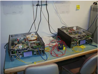
2Figure 6.1: The boxes Alice and Bob of the Clavis2 system of ID Quantique.
One Clavis2 system consists of two stations or two boxes, which can be seen in figure
6.1. As usual, one of the boxes is called Alice (QKDS-A) and the other one is called Bob (QKDS-B). One of the two is an id3100 Clavis2 and the other one is an id3110 Clavis2
system. The difference between the two numbers concerns the length of the delay line. The id3100 station has a delay line of twelve kilometers, whereas id3110 has a delay line of 24 kilometers. The boxes are controlled by an external computer, which must run on a the Ubuntu version of the Linux operating system.
There are two possible configurations of the system, a single- or double-computer con-figuration. In the single-computer configuration, one computer is used to control both the QKDS-A and QKDS-B stations. To control both boxes, two instances of the control programme must be ran on the same computer. Because there is just one computer that shows the key, this configuration does not allow key exchange over a distance to different locations. This configuration, though, is useful for testing and calibration purposes. Only the set-up with two computers can be used for key exchange to two different locations. In this configuration each device is controlled by a different computer, whilst a manage-ment (classical) channel is required for synchronization of the system and key distillation. This channel is implemented over a TCP/IP connection in a local area network, like the internet or a dedicated optical fibre. The computers can be linked to external encryption devices or other applications, for which the computers can provide the cryptographic key material.[22]
6.2.1
Software
The process of key distillation is called post-processing, which is fully implemented and automated in the systems. Post-processing of the raw key material consists of four main steps:
1. Sifting implemented both for BB84 and SARG04 2. Distillation of the key which consists of two steps:
• Key reconciliation, which is performed by the Cascade algorithm[3]
• Privacy amplification, which is performed by Wegman-Carter Strongly Uni-versal Hashing[14]
3. Authentication, which is performed by universal-hashing with One-Time Pad encryp-tion[4]
4. Key material storage and management
The software suite consists of five different applications. First, the QKD Menu Appli-cation, second a QKD Sequence AppliAppli-cation, third a QKD Log Analyzer Tool, fourth a QKD Device Access Library and finally a QKD Secure Chat Tool. A short explanation of these applications is as follows. First, the QKD Menu Application is a tool by which the id3100/id3110 Clavis2system can be controlled and operated. Access to all the hardware
parameters is provided by this application. Second, the QKD Sequence Application is a fully automated programme that controls the Clavis2 system. It sequentially performs
the tasks required for quantum key distribution. This application also stores the crypto-graphic key material that is produced in a key storage. This key storage can be accessed by other applications and external devices. Third, the QKD Log Analyzer Tool is a pro-gramme by which the log files produced by Clavis2 can be read. It can also be used to
graphically display key parameters and variables in order to analyze their temporal evolu-tion. Fourth, the QKD Device Access Library is a library of more than fifty functions that can be used to programme the system. It allows users to write customized programmes accessing the system to perform the tasks required by quantum key distribution. Finally,
the QKD Secure Chat Tool is a messaging application allowing the exchange of encrypted messages between computers connected to the stations of the Clavis2 system. For more specifications of the Clavis2 system see the brochure of ID Quantique.[22]
Now that we have seen the whole software suite of the system, implementing the quantum key distillation, we shall take a look at the physical implementation of the system.
6.2.2
Physical implementation
Figure 6.2: Quantum key distribution between Alice and Bob with Clavis2.
The schemes of both the devices are shown in appendix 10 (page 41). We will now explain the devices on the base of these schemes. The main text will not explain all of the components, for a detailed explanation of all the components see appendix 10 (page 43). Furthermore, the laser and the detector are explained in section 7.3. The id3100/id3110 Clavis2 system is based on an auto-compensating interferometric set-up. Hereafter, we
will explain what this means.
Roughly speaking, what happens inside the device is that a light pulse is sent from Bob to Alice. Alice attenuates the light beam to a single-photon-level amplitude and modulates the relative phase of the photon. A Faraday mirror reflects the photon back to Bob. The photon that goes back to Bob is detected in one of the two detectors. This set-up is called auto-compensating or, the so-called plug-and-play design. This QKD system is based on a interferometer. A schematic illustration is shown in figure 6.3.
There are a couple things that have to be kept in mind before we go through the system process. First, the measurements are based on the relative phase of the photons, so this phase carries the quantum information. There are two measurement bases, 0 and
π
2. In the first base the phases 0 andπrepresent the bits 0 and 1. In the second base,
π
Figure 6.3: The interferometric set-up of Clavis2. Alice can choose between the four
states: 0, π
2, πen 3π
2. Bob can choose between the two bases, 0 and π.
and 3π
2 represent the bits 0 and 1. Second, the polarization of the photons is only used
to make sure that all photons travel over the same distance, rather than for any quantum state measurements. Third, the laser sends a beam of photons. However, it is intended that just one photon eventually reaches Alice. This is the reason why the light intensity is reduced during the process. It is reduced in such a way that from every pulse of light eventually on average one third of a photon remains.[29]
Figure 6.2 gives a view on the inside of the boxes of Clavis2. We will now explain, step
by step, the path of the photons through these boxes. First, Bob’s laser sends a beam of photons, which is then separated by the 50/50 coupler after passing the circulator. The phase modulator, which the photons then pass, has no effect on this light beam yet. Then the photons pass the polarizing beam splitter, which splits the photons in two beams according to the polarization of the photons. Then, one of these two light beams is lost. The upper light beam in the scheme is then split by a 10/90 coupler to reduce the amount of photons in the direction of the Faraday mirror. The bottom light beam is attenuated and the photons are measured by three different detectors. These detectors are used for calibration processes and also to verify the light intensity en frequency to perform a first check on whether there is an eavesdropper active.
The upper light beam is also attenuated and subsequently the bandpass filter only selects photons of a frequency of about 200 Gigahertz. Then the delay line and the phase modulator, which again has no effect yet, are passed. At this time, there is only one photon left, which is in a superposition. This means that this one photon took both paths at the beginning, so it kind of “splits”. Then the photon is reflected with
orthogonal polarization, by the Faraday mirror. A little further, it becomes clear why this is important. On its way back, both “superpositions” of the photon first pass Alice’s phase modulator. Alice then chooses a phase shift for this photon, which is done by a random number generator. She can choose the rotations 0, π
2, π and 3π
2, but she only
rotates the phase of one of the two “superpositions”, the other one is the reference signal. The phase difference that is generated is then the quantum state of the photon.
Then the photon returns its way back to Bob and passes the polarizing beam splitter again. Because of the orthogonal polarization, the photon will now take the other path than it did before. However, the photon took both paths the first time, so the “super-positions” will take both paths again, but conversely, relative to the first time. Now the reference signal takes the upper path and passes the second phase modulator, which is Bob’s. Bob now chooses the base in which he will measure. The random number gener-ator decides if this base will be 0 or π
2, which causes the phase of the reference signal to
change. Then both “superpositions” reach the 50/50 coupler exactly at the same time, because they both traveled over the same distance. At this point interference between both “superpositions” takes place. Due to particular properties of the 50/50 coupler, it can translate the quantum information, which is encoded in the relative phase of the “superpositions”, into the classical bits 0 and 1. When there is no phase difference, the photon will be transmitted and detected. On the other hand, when there is a phase difference ofπ, the photon will be reflected and detected by the other detector. These two possibilities represent the classical bits 0 and 1. In case the base chosen by Bob is not equivalent to that chosen by Alice, the phase difference will be π
2, and whether the
photon will be reflected or transmitted is completely random. This determines that only the qubits measured by Bob, in the same base that Alice chose, are useful for the eventual key.[29]
Chapter 7
Weaknesses of QKD devices
As we already mentioned, QKD protocols guarantee perfect security based on the laws of quantum physics. However, security proofs of these protocols necessarily assume an idealized model of equipment. Unfortunately, there is a big gap between this idealized model and currently commercially available quantum cryptographic devices. Loopholes caused by the discrepancies between the model and the actual devices can be used by eavesdroppers. Challenges of the physical implementations of QKD protocols can roughly be divided into three categories. There can be problems at both the preparation and the measurement. Then, the source and the detector must also be connected in some way. In this chapter, we will describe these technological challenges. In the next chapter we will discuss various possible attacks on quantum cryptographic devices, which utilize weaknesses in the practical implementation.
7.1
Preparation
In the protocols BB84 and SARG04 (see also sections 3.1.1 and 3.1.3), Alice is assumed to use a single photon source for the preparation of her states. But perfect single pho-ton sources do not exist in reality. Therefore, in practical implementations faint laser pulses are used to approximate single photon number states. In these faint laser pulses the photon number distribution obeys Poisson statistics. Of course, there is the small probability of generating more than one photon at the same time when using such a source. This multi-photon component is the main problem with these practical sources, since even small fractions of multi-photons can have big consequences for the security of the key for large losses in the quantum channel.[9]The security loophole caused by these
multi-photons is exploited in the photon-number-splitting attack, which we will discuss later.[28]
Since the probability of findingnphotons in a coherent state produced by a practical source follows Poisson statistics:
P(n, µ) = µ
n
n!e
−µ
the probability that a nonempty weak coherent pulse contains more than one photon is P(n >1|n >0, µ) = 1−P(0, µ)−P(1, µ) 1−P(0, µ) = 1−e−µ(1 +µ) 1−e−µ ∼= µ 2. (7.2) Hence, this probability can be made arbitrarily small by decreasing the mean photon numberµ. However, whenµis really small, which is necessary for minimizing the effects of multi-photon states, most pulses are empty, for
P(n= 0)≈1−µ.
It is possible to compensate for the decrease in bit rate caused by these empty pulses, thanks to high modulation rates of the lasers. But a high modulation rate results in more dark counts. A dark count means that a detector gives a click, even though no photon is arriving. Therefore, really low mean photon numbers cannot be used. In most experiments the value µ= 0.1 is used,[1] by which approximately 5% of the nonempty
pulses contains more than one photon. There exists an optimal value forµ, depending on the transmission losses.[16]So, despite of these high modulation rates, using faint laser
pulses still results in a relatively low speed of QKD.
Of course, an ideal single photon source, which emits exactly one photon whenever Alice wants it to, would solve the multi-photon problems. Due to their low quantum efficiencies, these sources, so-called photon guns, currently do not offer an advantage over faint laser pulses with a very low mean photon number.[9] However, in the future there
might be some improvements in this field.
7.2
Channels
When Alice and Bob want to use QKD, they need to connect the source and the detector by a communication channel that can transmit quantum information, a so-called quantum channel. Since in practical implementations photons are used as qubits, light must be transmitted from Alice to Bob in some way. This could be accomplished either through an optical fibre or through free space.
Free-space QKD can be used when no optical fibre is available or in satellite communi-cation, but since this is not yet commercially available, it is beyond the scope of our text and we will only discuss it briefly here. However, we will mention the possible future for free-space quantum cryptography in the discussion at the end of this review. Since with free-space QKD the signals are not transmitted in a fibre, the transmitted energy spreads out, which leads to higher transmission losses. Moreover, light from outside can lead to a higher error rate. Even at night moonlight and city light could cause errors. Also the weather could influence free-space QKD. Finally, the performance of free-space systems depends highly on atmospheric conditions and is not possible in for example fog.[9, 23]
QKD through optical fibre is not influenced by the weather or by diffused light, but it does have its own difficulties. First of all, Alice has to avoid any correlation between the polarization of the photons and their frequency, for an eavesdropper could use such a correlation to gain information about the polarization of the qubits. Another challenge is that the bases that Alice and Bob use must be related by a stable transformation. For instance, the systems can be aligned by defining the vertical en diagonal directions.
When Alice and Bob know this transformation, they can compensate for the difference in their bases. In this way, they can obtain the required correlation between preparation and measurement. A big problem with quantum channels is that the transmission losses depend exponentially on the length of the fibre.[27]And since lost photons are correlated
to the signal, they must be counted as information gained by Eve. Therefore, the length of the optical fibre used for QKD is bounded, which means Alice and Bob cannot be too far apart.[27]
7.3
Detection
The last technological challenge we discuss here consists of the problems at the level of detection. The detector is the Achilles’ heel of most practical implementation of QKD, as most possible attacks aim at the detectors. An ideal single photon detector must have a high detection efficiency for a large range of frequencies. Also, the probability of giving a signal without a photon arriving (a dark count) must be as small as possible. Besides, the dead time of the detector, which is the time it takes to reset the detector after a click, must be short, since to date high data rates are only possible if the detector recovers quickly. Unfortunately, no real single photon detector completely meets these conditions. We will discuss two kinds of single photon detectors and their possible weaknesses here: threshold detectors with avalanche photodiodes and superconducting single photon detectors.[28]
7.3.1
Avalanche photo-diodes
An avalanche photo diode (APD) detects single photons by measuring the breakdown of a photo diode. A voltage is applied over the photo diode opposite of the direction of conductivity of the diode. It is slightly beneath the breakdown voltage, such that a single photon can trigger the breakdown of the diode. When a breakdown happens the diode rapidly starts to conduct current, which in turn leads to a decrease in voltage over the diode. This drop in voltage is then measured and used as the output of the avalanche photo-diode.
The drop in voltage also causes the diode to stop conducting, and the voltage can then slowly rise to slightly above the breakdown voltage, after which the detector is again ready to detect the next photon. During drop and rise of voltage the detector can effectively not measure another photon when it arrives, which limits the amount of photons the detector can handle.
These detectors typically operate at temperatures relatively close to room temper-ature, which makes them easier to handle, but is also the reason for their significant amount of dark counts.
7.3.2
Superconducting nanowire single photon detectors
Superconducting nanowire single photon detectors (SNSPD) consists of a thin wire which is cooled to superconducting temperatures. A current is then run through it, close to its critical current (the current at which it stops superconducting). When a photon then hits the wire, it will heat it slightly at its point of impact, locally reducing the critical current, which causes the wire to cease being a superconductor. This jump in resistance
is measurable and causes the click. The rise in resistance also reduces the current through the wire, causing it to cool down and become superconductive again.
SNSPD’s have the advantage that, because of their low temperature, their dark counts are rather low. Also, the process of cooling the wire is relatively fast, resulting in higher count rates being achievable.
7.3.3
Faked states
A problem with detectors is that faked states can be generated. Faked states are light pulses generated by Eve, which can force a detector to produce outcomes resembling those corresponding to the detection of single photons. Faked states can be used for intercept-resend attacks that we will discuss further in this text. Another difficulty is that photon detectors can be manipulated so as to change their timing behavior. In this way, Eve can make the detection time partly correlated with the detection outcome. This can be used for time-shift attacks, which we will also explain later. Another attack that aims at the photon detectors is called quantum blinding.
Chapter 8
Possible attacks
Since in practical implementations of QKD the devices are not perfect, Eve can do a hacking attack, which is related to the weakness of a specific implementation. Here we will discuss several possible attacks: intercept-resend attacks, the photon-number-splitting (PNS) attack, the time-shift attack and quantum blinding attacks.
8.1
Intercept-resend attacks
The simplest type of possible attack is the intercept-resend attack. Eve intercepts the photons sent by Alice and measures them in randomly chosen bases. Then she sends replacement states to Bob, prepared in the base she used for measurement. In QKD this will lead to errors in the key. Eve has a 50% probability to measure the photons in the right base, and when she uses the wrong base, she gets a random result which still has a 50% probability to be the right outcome. Therefore, the probability an intercepted photon generates an error in the key string is 50%·50% = 25%. When Alice and Bob are done transmitting the photons, she and Bob comparenof their key bits, using a public channel. If Eve has eavesdropped all bits, the probability they find disagreement and thus identify the presence of Eve, isPd= 1−(34)n. Therefore, if Alice and Bob compare
n= 72 key bits, there is a probabilityPd= 0.999999999 to detect Eve. So thanks to the
laws of quantum physics, this attack does not really work well theoretically, since it is easy for Alice and Bob to detect an eavesdropper with high probability.
8.1.1
Faked states attack
But, fortunately for Eve, there are more possibilities for intercept-resend attacks due to weaknesses in the practical implementation of QKD systems. An example of such an attack is the faked states attack, which we will discuss now. In a faked states attack on a QKD system, Eve does not try to reconstruct the original states sent by Alice, but generates light pulses, called faked states, that are detected by Bob in a way controlled by Eve. A successful faked states attack would give Eve full knowledge of the key. Faked states attacks can be run against several systems, even against systems with active base choice on Bob’s side.[20] In these attacks Eve forces Bob to measure the states in a base
chosen by Eve, instead of a randomly chosen base. Eve breaks into the channel between Alice and Bob and connects the fibre running from Alice to an equivalent of Bob’s set-up. She detects every state sent by Alice and notes the detection base she uses and the bit value she measured. After that, she sends a faked state towards Bob for every state she detected, using her own detection base to send the faked state. Bob detects these states in the base Eve forces him to. Alice and Bob will not notice Eve’s presence, because after the key sifting process all the key bits have been detected by Eve in the proper base. Therefore, when Alice and Bob compare their key bits, they will not find an increase in the quantum bit error rate. Eve can then watch the classical public communication between Alice and Bob and perform the same sifting, error correction and privacy amplification as Bob to obtain the same key.[8, 20]
The faked states attack contains a few challenges for Eve. First of all, she has to break into the channel between Alice and Bob. Eve needs two switches for this, one for splitting off photons from the line and another one for sending pulses down the line to Bob. The easiest possibility for this would be installing a tap before installation of the quantum link. If Eve knows about installation plans in advance, she could install the equipment onto the fibre and wait until Alice and Bob begin to use it for QKD. If this is not the case, she could install a tap when the channel is not in operation, for instance during maintenance. If the channel is constantly running, Eve would need a method that does not interrupt the channel. This is of course the most difficult option for her. When Eve has broken into the channel, she still needs a way to control the bases in which Bob measures. Eve can do this by making use of the weaknesses of Bob’s detector. There are several known ways to force the desired response from Bob’s device. For instance, base choice via polarization,[20]time-shift attacks and quantum blinding. We will discuss the
last two kinds of attacks later in this review. Faked states attacks are difficult for Eve and most of the time they are not very likely to succeed. But the fact that it is hard for Eve does not mean it guarantees perfect secrecy for the quantum cryptosystem.
8.1.2
Phase-remapping attack
Another intercept-resend attack is the phase-remapping attack. This is a so-called Trojan horse attack, which is an attack in which Eve sends signals that enter Alice’s and Bob’s devices through the quantum channel. One key assumption of QKD protocols is that Alice can prepare the required quantum states without errors. Even though this might seem like a simple assumption, it may be violated in practical QKD systems. Phase-remapping attacks exploit this loophole.[33]
In a plug-and-play QKD system, like the ID Quantique system discussed in chapter 6, Bob sends two laser pulses to Alice, a signal pulse and a reference pulse. The actual information is encoded in the relative phase between both pulses. Alice uses the reference pulse to determine when she should activate her phase modulator. Then Alice only modulates the phase of the signal pulse, attenuates the pulses to single photons and sends them to Bob. Since Alice allows signals to go in and out of her device to do this QKD, Eve gets the chance to do the phase-remapping attack. Eve can time-shift the single pulse so that is arrives at the phase modulator earlier or later than it should. Then the signal will be partially modulated and the relative phase between the signal pulse and the reference pulse will be smaller than it is supposed to be. In this way, Eve can even
remap the phase information from{0, π/2, π,3π/2} to{0, δ,2δ,3δ}.[7]
Since Eve can change the phase differenceδbetween the states sent by Alice, she can launch an intercept-resend attack that is optimized for this particular phase difference. If she used a simple intercept-resend attack as described earlier without phase-remapping, it would result in a quantum bit error rate of 25%. Bob and Alice would then discard their key and start over. So, Eve needs an attack that leads to situations in which Alice and Bob believe that they can generate a secret key. It has been shown that it is possible to get a quantum bit error rate of 19,7% (this might even be improved in the future),[33]
while an error of 20% is tolerable in the BB84 protocol without any Trojan Horse attacks (and 19,9% in the SARG04 protocol),[7] meaning that a secret key can be distilled. If
Alice and Bob are not aware of phase-remapping attacks, they would distill a key that they assume to be secret and Eve will get information about the key. Consequently, Alice and Bob will need a lower tolerable error percentage for secret key distillation.
8.2
Photon number splitting attack
As we already mentioned in the paragraph about photon sources, perfect single photon sources do not exist (yet). And since the photon number distribution obeys Poisson statistics, there is a small probability of generating more than one photon at the same time. When this happens, Eve can split off one of the photons and transmit the remaining photon to Bob. Eve can store the obtained photons until Bob detects the matching photons and Alice reveals the bases she used. Eve can then measure her photons in the same base en in this way obtain information on the key, without being noticed by Alice and Bob. This is called the photon number splitting (PNS) attack. Even with the possibility of a PNS attack, Alice and Bob can still generate a secure key. However, this significantly reduces the secure key rate.[10]
A solution to PNS attacks is the use of decoy states. Alice prepares a set of states in addition to the standard states she wants to send to Bob, called decoy states. These states are only used for the purpose of detecting eavesdropping, rather than for key generation. For decoy states, Alice randomly uses different low mean photon numbers for her photon source. For example, she could send the first pulse withµ= 0.1, the second pulse withµ= 0.4, the third pulse withµ= 0.05 etcetera. Each different mean photon number has its own probability of producing more than one photon in a pulse. These mean photon numbers are the only difference between the decoy states and the standard states. Therefore, Eve cannot distinguish a decoy state from a signal state and the only information she gets is the number of photons in a signal. Thus, decoy states can be implemented to secure against PNS attacks, while allowing high key rates.[15]
8.3
Time-shift attack
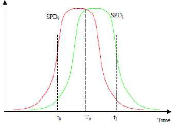
Another attack that aims at the detectionstage, is the time-shift attack. It makes use of the detection efficiency loophole. Most QKD systems have two or more single photon detectors. In an ideal situation, those detectors are identical. But in practice it is hard to build two identical detectors. Therefore, an efficiency mismatch could exist in the time domain.[13] When a signal is sent from Alice to Bob, one of Bob’s detectors should give
Figure 8.1: Time difference in times of maximum detection efficiency between 2 detectors.
a click. To minimize the dark count rate, APD’s usually work in “gated mode”: they are activated by a gate signal for a narrow window only when a signal is expected to arrive. Outside that window, the detectors do not respond to the incoming signals. At the moment the signal arrives, the efficiency of the detector should be as high as possible, to detect the signal with a high probability. Moreover, every detector should have a high efficiency at the same time. Then both detectors have the same probability to give a click. In practical implementations however, this is not always the case. When Alice and Bob calibrate their devices, such a mismatch is sometimes observed. There is a shifting between the efficiency curves. (see fig. 8.1)[21] This mismatch can be used for time-shift
attacks.
Eve can delay or advance pulses from Alice to Bob by using high speed optical switches to re-route Alice’s signal through either a long or short optical path. When there is an efficiency mismatch in the time domain, one of the detectors will have a higher probability to click when the signal is time-shifted back- or forward. But to use this, Eve needs to know in which direction the shifting is. She wants the shift to be large enough to perfectly distinguish the detectors. This is a limitation of the time-shift attack, since the mismatch is only large enough in merely 4% of all attempts.[35] Now Eve can randomly time-shift
signals back or forward and with a higher probability she knows which detector will click. But, with only a time-shift attack, Eve will not be able to get the full information on the sifted key. Then it might be still possible for Alice and Bob to create a secret key. To avoid this, Eve can use a faked states attack. Compared to the intercepted measurements, she prepares the opposite bit value in the opposite base and sends it. She can send it with such a timing that the detection of the opposite bit value is suppressed, because of the low detection efficiency. In this way, she acquires information on the key without Alice and Bob noticing.[13]
the mismatch is not too high by measuring other parameters. Another way to