Physics Procedia 25 ( 2012 ) 1816 – 1822
1875-3892 © 2012 Published by Elsevier B.V. Selection and/or peer-review under responsibility of Garry Lee doi: 10.1016/j.phpro.2012.03.316
2012 International Conference on Solid State Devices and Materials Science
Reliability Analysis of Aircraft Equipment Based on FMECA
Method
Li Jun, Xu Huibin
Department of Aviation Control and Engineering Aviation University of Air Force Changchun, Jilin Province, China
Abstract
It is well known that reliability of aircraft equipment is very important to aircraft during the flight because performance of aircraft product can affect flight safe directly. In order to make the equipment work normally, FMECA is applied in an aircraft equipment to analyze its reliability and improve operational reliability of the product. Through its reliability mathematical model, average of operational time is predicted based on calculating failure probability of all electrical components. According to the process of reliability theory FMECA, all kinds of the failure mode, reasons, effects and criticality of the products can be determined completely. By comparing these criticality data as shown, the paper analyses adopted method by that the contents, accents and operating process of maintenance may be instituted finally. FMECA-based method for reliability analysis of the equipment and the equipment maintenance performs well. The results indicate that application of FMECA method can analyze reliability in detail and improve operational reliability of the equipment. Therefore this will supply theoretical bases and concrete measures of maintenance of the products to improve operational reliability of products. FMECA can be feasible and effective for improving operational reliability of all aircraft equipments.
© 2011 Published by Elsevier Ltd. Selection and/or peer-review under responsibility of [name organizer]
Keywords:Reliability Analysis, Aircraft Equipment, FMECA
1. Introduction
With the development of electronic technology, the performance of the aircraft equipments tends to be growing better. In order to ensure their working order, enhance their performance, the operational reliability of the aircraft equipments should be guaranteed. Low failure probability and long time running are required of plane-carried products [1]. Thus, it is necessary to analyze the reliability of products and do a good maintenance to the aircraft equipments under the guidance of proper theories. Failure Mode Effect and Criticality Analysis (hereafter called FMECA) is one of the methods for reliability analysis and valuation [2]. FMECA is designed to analyze all sorts of the potential failure in each component, and by analyzing and computing criticality, FMECA may tell the incoming failure and its effect, that is,
© 2012 Published by Elsevier B.V. Selection and/or peer-review under responsibility of Garry Lee Open access under CC BY-NC-ND license.
FMECA can tell the staff the exact service job [3]. According to what has been produced by FMECA, a well-scheduled job list may be done to enhance the reliability of the plane-carried equipments.
Aiming at the plane-carried equipment of a certain type of aircraft and applying FMECA, we conducted its reliability modeling and prediction of average of operational time [4], pointed out the issues which should be paid attention to in maintenance while using the equipment, thus ensure and improve the operational reliability of the plane-carried equipment. In the following part, this equipment is used as an example to introduce the process and effect of using FMECA method.
2. The modeling of the aircraft equipment reliability
The reliability modeling of the aircraft equipments is conducted by dividing the whole working process into different functional system and sub-system, each of which fulfills its respective function and finally the systematic functional diagram is designed. Based on this systematic functional diagram, the reliability model with one-to-one clear administrative levels is built, that is the reliability diagram of the aircraft equipment [5].
2.1 The Main Structure and Functions of the Equipment
According to the design and application characteristics of the equipment, the systematic functional diagram is formed. Based on this, this equipment can be divided into eight functional modules: microcomputer system, pulse width regulating D/A converter, volt-control vibes system, digital trigonometric function generator system, D/A transition network system, numerical control gaining system, power magnification system, and display system [6]. The main function can be further divided into the sub-systems which fulfill the most basic functions. For example, D/A transition network system, used to realize the production and output of the analog quantity, consists of R/2R transition network and operational amplifier unit. Each sub-system can also be divided into parts and components and other apparatus. This kind of division is in accordance with units of the equipment while designing and manufacturing.
2.2 The Reliability Diagram of the Equipment
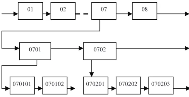
Based on the systematic functional diagram, those parts and components which have the same function are used to form a sub-system, and many sub-systems form the reliability system of the equipment. The reliability modeling is conducted according to the function each part fulfills and then the whole system is divided into many sub-systems, and the sub-system is further divided into individual part and component. The reliability diagram is drawn according to this. The reliability diagram should be in accordance with the schematic diagram of the whole equipment and with all the functional part. Then, the encoding process is conducted according to the hierarchy relation of system and sub-system. The eight functional modules are seen as eight systems and are encoded as microcomputer system (01), pulse width regulating D/A transmitter (02), Volt-control vibes system (03), digital trigonometric function generator system (04), D/A transition network system (05), numerical control gaining system (06), power magnification system (07), and display system (08). The sub-systems, parts and units in each system are also encoded. For example, RAM (010310), etc. The reliability diagram is shown in Figure 1.
y ( )
Fig. 1 Reliability diagram of the aircraft equipment 2.3 The Reliability Mathematical Model of the Equipment
The reliability mathematical model of the tester while working is shown in formula (1) and (2).
¦
i sO
O
. (1) s sMTBF
1
O
. (2)Ȝs——failure probability of the equipment.
Ȝi——failure probability of Unit i.
MTBFs——average of interval between failures of the equipment.
3. The prediction of the reliability
The prediction of the reliability of this equipment starts with the parts and components and ends with the whole equipment [7]. The data are from the GJB/Z299-91. We also refer to the external field data of some other similar products [8]. For example, the resistance R in the numerical control gaining system,
n=30, the working failure probability model of the resistance is: Ȝp=Ȝb×E×Q×R. Since S=0.3,
according to Chart 2.4.1—5, Ȝb=0.056×10⁻⁶/h. according to Chart 2.4.1—1, 2.4.1—2, and 2.4.1—3,
E=1, Q=0.3, R=1.0. thus, Ȝp=0.056×10-6×1×0.3×1.0=0.0168×10⁻⁶/h, the failure rate of all the
resistance Ȝ=Ȝi (i=1,2,•••,30) Ȝ=0.504×10⁻⁶/h. By using this method, we can get the failure rate (Ȝs) of
the equipment:
Ȝs=Ȝi=(1.45+2*0.01188+8*0.01133+•••)=985.7×10⁻⁶/h
MTBFs=1/Ȝs=1/(985.7×10-6)=1014.5(h)
4. The FMECA analysis of the equipment
4.1 The Working of FMEA
FMEA is a bottom-up failure analysis method.According to the FMECA working program of the reliability theory, conduct the FMEA analysis of the aircraft equipment [9].
1) List the Equipment Failure Model Checklist: According to the national military standard GJB299,
the reliability estimation handbook of electronic equipments and working experience of maintenance, list the typical failures of this equipment.
2) Reasons Analysis: Analyze the reasons causing the failures. Careful analysis should be conducted to judge every possible failure or problem, such as the reason of joins and quality.
01 08
0701 0702
070101 070201
02 07
3) Possible Effect: Analyze the possible effect of each problem to the part or component itself, to the
upper level and to the whole equipment.
4) Measures: Propose some possible preventive measures according to each kind of problem model,
reasons and effect.
5) Degree of the Seriousness of the Failures: The degree of seriousness can be classified into the following four types: Type I (disastrous), Type II (fatal), Type III (critical) and Type V (slight).
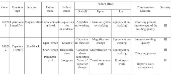
Take D/A transition network system for example, FMEA analyzing table of some parts and components is shown in Table I.
TABLE I D/A Transition Network System Fmea Code Function sign Function Failure mode Failure cause Failure effect Compensation Measure Severity
Oneself Upper Last
05020 1
Operationa l amplifier
MagnificationLoose contact or break Disqualifica-tion or solder-off Amplifier no-working Transition system no-working Equipment no-working Choosing product improvement of the welding quality ċ 05020 2 Capacitor (100PF) Feed-back Open-circuit Short-circuit Parameter-drift Solder-off Disqualific-ation Long-use Capacitor no-function Capacitor short-connection Value of capacitor change Magnification change Magnification =1 Transition system work Equipment no-working Equipment no-working Equipment work Improve welding quality Choosing product Improve daily maintenance ċ ċ Č
4.2 The CA Analysis of the Equipment
Under a specific degree of seriousness, the criticality value of a certain failure model in those failure
models is Cmj. As for a given degree of seriousness and a given phase of mission, the Cmj of the number j
of the product can be calculated by using the following formula: Cmj=Ȝp*Įj*ȕj*t. In this formula, Įj shows
the percentage of failure displayed as model j. If all the failure models of a product are listed, the totality
of Įj would be 1. ȕj, a number got by the analyzing faculty from their working experience, is the
conditional probability of the lose of the systematic mission when the product breaks down as model j. The working time t can be calculated from the definition of the system. Generally, it is shown by the hours used to finish each mission or by the times of the working circle. The Cr (the destructive degree of a product) refers to the estimated failing numbers of a certain type of product caused by this failure model
of the product. As for a given degree of seriousness and a given phase of mission, Cr is the totality of Cmj
under this degree of seriousness. Cr can be calculated according to the following formula:
C
C
j jt
n j p n j mj r¦
¦
O
D
E
1 15. the application of FMECA
5.1 Work Out the Content of Maintenance of the Equipment
According to the working of FMEA, the failure models of product in each system which form the product are seen as the daily maintenance content of the equipment. The failure models of Type III and Type IV totaled 45 items, all of which have been written in the maintenance and using manual attached to the equipment.
5.2 Determine the Key Maintenance Point of the Equipment
Based on the FMEA and CA reliability analysis, the key and important parts of the equipment are CPU, crystal, LED, program and data memorizer, AD652, 74HC573, 74LS393,
D/A transition system adjust resistance, and 74LS273 etc. In the work of maintenance, they are regarded as key target.
Effective measures should be taken to ensure the normal working of the equipment by considering the relative failure models.
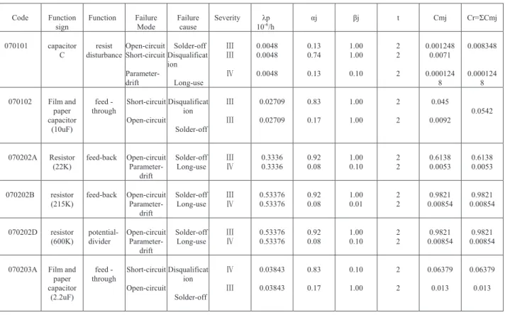
TABLE II Power Amplifier System Criticality Analysis (CA)
Code Function sign Function Failure Mode Failure cause Severity Ȝp 10-6/h Įj ȕj t Cmj Cr=ȈCmj 070101 capacitor C resist disturbance Open-circuit Short-circuit Parameter-drift Solder-off Disqualificat ion Long-use ċ ċ Č 0.0048 0.0048 0.0048 0.13 0.74 0.13 1.00 1.00 0.10 2 2 2 0.001248 0.0071 0.000124 8 0.008348 0.000124 8 070102 Film and paper capacitor (10uF) feed -through Short-circuit Open-circuit Disqualificat ion Solder-off ċ ċ 0.02709 0.02709 0.83 0.17 1.00 1.00 2 2 0.045 0.0092 0.0542 070202A Resistor (22K) feed-back Open-circuit Parameter-drift Solder-off Long-use ċČ 0.3336 0.3336 0.92 0.08 1.00 0.10 2 2 0.6138 0.0053 0.6138 0.0053 070202B resistor (215K) feed-back Open-circuit Parameter-drift Solder-off Long-use ċČ 0.53376 0.53376 0.92 0.08 1.00 0.01 2 2 0.9821 0.00854 0.9821 0.00854 070202D resistor (600K) potential-divider Open-circuit Parameter-drift Solder-off Long-use ċ Č 0.53376 0.53376 0.92 0.08 1.00 0.10 2 2 0.9821 0.00854 0.9821 0.00854 070203A Film and
paper capacitor (2.2uF) feed -through Short-circuit Open-circuit Disqualificat ion Solder-off Č ċ 0.03843 0.03843 0.83 0.17 0.10 1.00 2 2 0.06379 0.013 0.06379 0.013
5.3 Work Out the Reasonable Maintenance Working Method
Calculate the criticality of product according to the failure models of the product in all the systems. Under the principle of maintaining those parts which have high degree of destruction first, work out reasonable maintenance working order based on the order of the criticality data. Considering the destructive degrees of those failures belonging to Type III and Type IV, the maintenance working order is given.
6. The application effect
After investigating the same type of aircraft equipments used in two airports A and B, we collected the mean lifespan data of the equipments in the two places and they are given in Table III and Table IV. In airport A, the maintenance of the equipments is not conducted according to the FMECA analysis, and in airport B, the maintenance of the equipments is conducted according to the FMECA analysis.
From the two tables above, we can find: the MTBF of airport A is 869 hours which is shorter than the estimated MTBF (1014.5 hours); while in airport B, the MTBF is 1009 hours, which is very close to the estimated MEBF. From the comparison, we can also find that, for those equipments which have been maintained according to the analysis of FMECA, their MTBF is much longer than that of other equipments, the operational time of the product is longer than before and the operational reliability is also improved.
TABLE III The Mean Lifespan Data Ofairport A (Unit: Hour)
Number 1 2 3 4 5 6 7
Interval time 810 840 1080 790 968 730
87 0 MTBF 869
TABLE IV The Mean Lifespan Data Ofairport B (Unit: Hour)
Number 1 2 3 4 5 6 7
Interval time 1010 990 1070 998 1050 1000 950
MTBF 1009
7. Conclusion
This paper conducts the reliability modeling of an aircraft equipment and predicts its MTBF. In order to analyze and improve its reliability, reliability technique FMECA method is used to analyze its failure models and destructive degree, thus propose content, key point and method which should be paid attention to while using and maintaining the equipment. The result shows that reliability analysis and the application of FMECA method prolong the lifespan of this equipment and improves the operational reliability greatly, thus proves that it is correct to apply this method to reliability analysis and improvement of operational reliability of a product. In the meantime, it may help to improve the reliability of other aviation products.
Acknowledgment
References
[1] Liu Lu-ning, “Reliability analysis of electric element in ground tester,” Aircraft Design, no.2, pp. 50-53, June 1998. [2] Chao Mao-guo and Qian Jin-shan, “Reliability analysis technology on aviation engine,” Aviation Engine, no.4, pp. 32-39, December 1995.
[3] Gong De-quan, “Application of FMECA method to improve design reliability,” Shanghai Space, no.3, pp. 25-29, September 1995.
[4] Establish Of Reliability Model and Reliability Prediction Manual, GJB813-90, National Science and Technology Committee, 1990.
[5] Ding Ding-hao, “Reliability and Maintenance Engineering,” Electronic Industry Press, pp. 362-367, October 1986. [6] He Li-min, “Design of Processor System,” Bei-jing University of Aeronautics and Aetronautics Press, pp. 106-128, 1990. [7] Chen Bing-sheng, “Electronic Reliability Engineering,” National Industry Press, pp. 71, May 1987.
[8] Reliability Prediction of Electronic Equipment Manual, GJB/Z299-91, National Science and Technology Committee, 1991.
[9] Lu Ting-xiao and Zheng Peng-zhou, “Design and Analysis of Reliability,” National Industry Press, pp. 140-149, September 1995.