DYNAMICS AND CHATTER STABILITY OF MULTI DELAY MACHINING SYSTEMS
by
Alptunç ÇOMAK
Submitted to the Graduate School of Engineering and Natural Sciences in partial fulfillment of the requirements for the degree of
Master of Science
Sabancı University July, 2013
DYNAMICS AND CHATTER STABILITY OF MULTI DELAY MACHINING SYSTEMS
Approved By:
Prof. Dr. Erhan BUDAK (Thesis Advisor)
Assoc. Prof. Bahattin KOÇ
Assoc. Prof. Bülent ÇATAY
Assoc. Prof. Ali KOŞAR
Assoc. Prof. Ayhan BOZKURT
© Alptunç ÇOMAK, 2013 All rights reserved
to my family,
i
DYNAMICS AND CHATTER STABILITY OF MULTI DELAY MACHINING SYSTEMS
Alptunç ÇOMAK
Industrial Engineering, MSc. Thesis, 2013 Thesis Supervisor: Prof. Dr. Erhan Budak
Keywords: Chatter Stability, Special Milling Tools, Parallel Milling, Parallel Turning
Abstract
Machining is an industrial process in which parts are shaped by removal of unwanted material in the forms of chips. Manufacturing industry today demands shorter production times and high quality parts at competitive cost. Increased MRR (material removal rate) in milling and turning may provide high productivity but elevated forces and vibrations are still major obstacles to fulfill these requirements. Chatter vibrations may limit the full potential of machining productivity. In this thesis, chatter stability of multi delay systems is investigated. As examples of multi delay systems, variable tooth spacing tools such as variable pitch and helix milling cutters and parallel milling operations are investigated. Although there are few studies about the chatter stability of variable tooth spacing tools, no work has been reported on optimum design for a given cutting condition. Optimization studies are carried out to determine the optimum variable tool geometry and a new design methodology is presented. Moreover, for parallel milling operations, an analytical solution methodology which is based on frequency domain analysis is proposed to solve the chatter stability for the first time in the literature. Optimum cutting conditions are identified and effects of process parameters and workpiece dynamics on the chatter stability of parallel milling are shown. Since the operation contains single time delay, optimization studies are carried out to determine the optimum cutter dynamic properties in parallel turning. Simulated conditions are verified by time domain and experimental tests.
ii
ÇOK FAZLI TALAŞLI İMALAT SİSTEMLERİNİN DİNAMİĞİ VE TIRLAMA KARARLILIĞI
Alptunç ÇOMAK
Endüstri Mühendisliği, Yüksek Lisans Tezi, 2013 Tez Danışmanı: Prof. Dr. Erhan Budak
Anahtar Kelimeler: Tırlama Kararlılığı, Özel Freze Takımları, Eş zamanlı Frezeleme, Eş zamanlı Tornalama
Özet
Talaşlı imalat, üretilecek parçaların talaş kaldırma yoluyla şekil verildiği endüstriyel bir üretim yöntemidir. Günümüzde imalat endüstrisi kısa üretim süreleri, yüksek ürün kalitesi ve rekabetçi fiyatlar talep etmektedir. Frezeleme ve tornalama operasyonlarında yüksek talaş kaldırma oranları üretim verimliliğini artırıcı yönde uygulanabilir olmasına karşın yüksek kesme kuvvetleri ve titreşim değerleri buna engel olmaktadır. Tırlama titreşimleri de talaşlı imalat verimliliğini kısıtlayan sebeplerden birisidir. Bu tezde çok fazlı talaşlı imalat yöntemlerinin tırlama titreşim kararlılığı araştırılmıştır. Çok fazlı talaşlı imalat sistemlerine örnek olarak, değişken adım ve helis aralıklı gibi özel freze takımları ve eş zamanlı frezeleme operasyonları incelenmiştir. Özel freze takımlarının tırlama kararlılığını modelleyen birçok çalışma olmasına karşın, literatürde verilen bir kesme koşulu için bu takımları dizaynına yönelik bir çalışmaya rastlanmamaktadır. Optimum takım geometrisini belirlemek için eniyileme çalışmaları yapılmış ve yeni bir tasarım metodu geliştirilmiştir. Bununla birlikte literatürde ilk kez eş zamanlı frezeleme operasyonlarının tırlama kararlılığının çözümü için frekans kümesinde bir analitik çözüm metodu geliştirilmiştir. En iyi kesme koşulları belirlenmiş, kesme parametreleri ve iş parçası dinamiğinin kararlılık limitine olan etkileri gösterilmiştir. Son olarak, her ne kadar sistem tek fazlı olsa da, eş zamanlı tornalama operasyonlarında en iyi takım dinamik özelliklerinin belirlenmesi yönünde çalışmalar yapılmıştır. Benzetimi yapılan tüm koşullar zaman kümesi modeli ve deneysel çalışmalar yardımı ile doğrulanmıştır.
iii
Acknowledgement
First, I would like to thank Prof. Dr. Erhan Budak who is the supervisor of this Master thesis. I owe my deepest gratitude for his intellectual input, guidance, encouragement and inspiration throughout my graduate studies. He has guided the thesis in such a way that the outcome of thesis is significant for both academy and industry. Other than guiding my academic career, he has also had considerable positive effect on my personal development.
Prof. Dr. Yusuf Altintas, who becomes my life mentor throughout my undergraduate and graduate education, is the paramount factor to apply to Sabancı University and work with Erhan Budak. Without his valuable advices and guidance, it would be too hard to see what is best for me and my future.
I greatly appreciate the support of my family throughout my education life. During my Master study period, I always felt their presence, immeasurable and durable support. I thank my mother Bengi Çomak, my father Zafer Çomak, my sister Muazzez Çomak, my grandmother Muazzez Bahadır and my uncle for being in my life. I dedicate this thesis to them for being my driving force for all my life.
S. Burçe Özler has been the source of joy, motivation and support in my life. Her presence has been essential particularly at the difficult times of my Master study. I thank her for her support and contributions to my life.
It is a pleasure to thank every member of Manufacturing Research Laboratory (MRL) who made this thesis possible both by providing academically and technically supports. Every former and present members of 1021 Office and my lab mates made my Master study enjoyable and memorable. Their support and friendship was unforgettable during two and a half years.
Lastly, I would like to thank TÜBİTAK (The Scientific and Technological Research Council of Turkey) for supporting me financially by granting a scholarship at the second year of my Master study.
iv
TABLE OF CONTENTS
Abstract ... i
Özet ... ii
Acknowledgement ... iii
LIST OF FIGURES ... vii
LIST OF TABLES ... xi
CHAPTER 1. INTRODUCTION ... 1
1.1. Organization of the Thesis ... 6
1.2. Literature Survey ... 7
CHAPTER 2. CHATTER STABILITY OF VARIABLE PITCH/HELIX TOOLS AND DESIGN OF OPTIMUM VARIABLE TOOL GEOMETRY FOR INCREASED STABILITY ... 10
2.1. Description of Variable Geometry Milling Tools ... 11
2.2. Chatter Stability of Variable Helix and Pitch Milling Tools ... 13
2.2.1. Semi-Discretization Method ... 13
2.2.2. Single Frequency Averaging Method ... 15
2.3. Optimization of Variable Helix and Pitch Milling Tools ... 17
2.3.1. Chatter Stability Simulations ... 18
2.3.1.1. Optimization of Variable Helix Alternate Tool ... 19
2.3.1.2. Optimization of Variable Helix Linear Variation Tool ... 21
2.3.1.3. Optimization of Variable Pitch Alternate Variation Tool ... 24
2.3.1.4. Optimization of Variable Pitch Linear Variation Tool ... 26
2.3.2. Experimental Verifications ... 29
2.3.3. Effect of Radial Depth of Cut on Optimum Solution ... 32
2.3.4. Design Methodology of Optimum Variable Tool Geometry... 33
Summary ... 39
CHAPTER 3. DYNAMICS AND CHATTER STABILITY OF SIMULTANEOUS MILLING OPERATIONS ... 41
v
3.1. Dynamics of Parallel Milling Operations ... 42
3.1.1. Dynamic Responses and Chip Thickness Definition ... 43
3.1.2. General Force Formulation of Parallel Milling ... 44
3.1.2.1. Delay Matrix and Transfer Functions Matrix ... 45
3.1.2.2. Relative Angular Position Offset ... 46
3.2. Chatter Stability of Parallel Milling Operations ... 47
3.3. Simulations and Experimental Results ... 49
3.3.1. First Case ... 49
3.3.1.1. Workpiece Design and Modal Testing ... 50
3.3.1.2. Effect of Workpiece Flexibility on Process Stability ... 52
3.3.1.3. Effects of Cutting Parameters on Process Stability ... 53
3.3.1.3.1. Effect of Different Number of Teeth on Stability ... 53
3.3.1.3.2. Effect of Working Mode of Cutting Tools ... 54
3.3.1.3.3. Effect of Radial Immersion on Stability ... 56
3.3.2. Second Case ... 56
3.3.3. Third Case ... 59
3.3.3.1. Time Domain Verification of Analytical Frequency Method ... 62
3.3.3.2. Effects of Workpiece Dynamics on Stability of the Process ... 64
Summary ... 69
CHAPTER 4. CHATTER STABILITY AND HIGH PERFORMANCE CUTTING CONDITIONS OF PARALLEL TURNING OPERATIONS ... 70
4.1. Formulation of Dynamics and Chatter Stability of Parallel Turning ... 71
4.2. Optimization of Parallel Turning Operations ... 73
4.2.1. First Method: Mass Change at Cutters ... 74
4.2.2. Second Case: Length Change of Cutters ... 83
Summary ... 89
CHAPTER 5. CONCLUSION ... 90
vi
vii
LIST OF FIGURES
Figure 1.1. Machined parts (a) blisk, (b) camshaft and machine tool (c) NTX2000
Multi-purpose Machine Tool. ... 1
Figure 1.2. Delay between the vibration marks of the tooth j and tooth j+1. ... 2
Figure 1.3. Stability diagram and surface photo and variation of cutting forces at stable and unstable conditions. ... 3
Figure 1.4. Sample demonstration of parallel milling operation. ... 4
Figure 1.5. Demonstration of parallel turning operation. ... 5
Figure 2.1. Tool geometry of variable pitch tool. ... 11
Figure 2.2. Tool geometry of variable helix tool. ... 12
Figure 2.3. Unfolded tool geometry and variable flute parameters. ... 13
Figure 2.4. Dynamic chip thickness and two orthogonal degrees of freedom. ... 14
Figure 2.5. Flowchart of the iterative solution methodology. ... 17
Figure 2.6. Stability diagrams vs. variation in the helix angle for a alternating helix milling tool. ... 20
Figure 2.7. Stability diagrams for regular and variable helix tool with optimal variation. ... 20
Figure 2.8. Variation of chatter frequency with helix angle alteration. ... 21
Figure 2.9. Stability diagrams vs. linear variation in the helix angle. ... 22
Figure 2.10. Cross-sections of the 3D stability diagram. ... 22
Figure 2.11. Comparison of regular and optimum variable helix with linear variation tool. ... 23
Figure 2.12. Variation of Chatter Frequency with linear helix angle variation measure. ... 23
Figure 2.13. Variation of the stable depth of cut with spindle speed and alternating pitch angle. ... 24
Figure 2.14. Comparison of regular and optimum alternatingly variable pitch tool. ... 25
Figure 2.15. Variation of stable depth of cut with pitch variation amount ... 25
Figure 2.16. Variation of chatter frequency with alternatingly pitch angle variation amount. ... 26
Figure 2.17. Variation of the stable depth of cut with spindle speed and linear pitch angle. ... 26
viii
Figure 2.18. Comparison of optimum variable linearly varying pitch tool and regular
tool. ... 27
Figure 2.19. Comparison of alternate and linear variations for variable pitch tool. ... 28
Figure 2.20. Comparison of optimum variable helix, pitch and regular end mill tools. . 29
Figure 2.21. Test setup. ... 30
Figure 2.22. Stability diagram and test results for tool 1. ... 30
Figure 2.23. Sound FFT and surface photo of point A. ... 31
Figure 2.24. Sound FFT and surface photo of point B. ... 31
Figure 2.25. Stability diagram and test results for tool 2. ... 32
Figure 2.26. Equivalent wave length corresponds optimum pitch variation. ... 34
Figure 2.27. Phase difference between present and previous waves. ... 35
Figure 2.28. Flowchart of the optimum pitch variations analysis. ... 35
Figure 2.29. One full vibration wave on the cutting surface. ... 36
Figure 2.30. Flowchart of the iteration method for calculation of the optimal pitch variation. ... 39
Figure 3.1. Illustration of dynamic couplings a) workpiece compliance b) machine tool compliance. ... 42
Figure 3.2. Geometry of simultaneous milling. ... 43
Figure 3.3. Angular offset between two milling tools. ... 46
Figure 3.4. Modal analysis of the workpiece in Abaqus© software. ... 50
Figure 3.5. Technical drawing of the workpiece. ... 50
Figure 3.6. Designed workpiece. ... 51
Figure 3.7. Modal testing of (a) workpiece and (b) tools. ... 51
Figure 3.8. Frequency Response Function of workpiece and tools. ... 52
Figure 3.9. Effect of workpiece flexibility on stable depth of cuts. ... 53
Figure 3.10. Effect of number of teeth on stability of the process. ... 54
Figure 3.11. Variation of absolute stability value with number of tooth. ... 54
Figure 3.12. Illustration of a) upmilling and b) downmilling operation in parallel milling. ... 55
Figure 3.13. Effect of working modes to process stability. ... 55
Figure 3.14. Effect of different radial depth of cut values on the stability diagram. ... 56
Figure 3.15. Workpiece and the test components for Case 2. ... 57
Figure 3.16. Test set up for modal (hammer) test. ... 57
ix
Figure 3.18. Predicted stability diagram and the experimental results. ... 59
Figure 3.19. Designed workpiece. ... 60
Figure 3.20. First three modes of the workpiece. (a) Bending mode (b) Torsional mode (c) Bending mode in z direction. ... 60
Figure 3.21. 3D stability diagram. ... 61
Figure 3.22. Variation of Stability limit with spindle speed of second tool. ... 62
Figure 3.23. Stability diagram at spindle speed of 4000 rpm of the second tool. ... 62
Figure 3.24. Cutting forces in y direction (a) a1=2.5 mm (b) a1=3.5 mm ... 63
Figure 3.25. Effect of phase angle on stability limit, tool 1. ... 64
Figure 3.26. Cutting forces in y direction on the tools. ... 64
Figure 3.27. Workpiece and the experimental setup. ... 65
Figure 3.28. ANSYS example for the fourth zone. ... 66
Figure 3.29. Stability diagrams for each zone. ... 67
Figure 3.30. Experimental verifications. ... 68
Figure 3.31. Accelerometer data and surfaces of stable and chatter zones. ... 68
Figure 4.1. Parallel turning operation on the same surface. ... 71
Figure 4.2. Stability diagram with two limits (a2 = 1.5 mm). ... 73
Figure 4.3. Stability diagram for the case of r = 1.11 and time domain verification. ... 76
Figure 4.4. Stability diagram for the case r = 1. ... 78
Figure 4.5. Stability diagram for the case of r = 0.91. ... 78
Figure 4.6. 3D stability diagram for the r < 1 case. ... 79
Figure 4.7. 3D stability diagram for the r >1 case. ... 79
Figure 4.8. Variation of upper and lower limits of the first tool with different “r” ratios for a constant value of the ... 80
Figure 4.9. Variations of dynamic chip thickness and cutting forces at points A, B and C. ... 81
Figure 4.10. FRFs of the cutters when r=1. ... 82
Figure 4.11. FRFs of the cutters where . ... 82
Figure 4.12. Variation of FRF amplitude with the r ratio. ... 83
Figure 4.13. Variation of length of the cutter with its natural frequency. ... 84
Figure 4.14. Variation of a2 with the lower and upper limits of a1 for L > 1... 85
Figure 4.15. 3D stability diagram for the L < 1 case. ... 86
Figure 4.16. 3D stability diagram for the L > 1 case. ... 86
x
Figure 4.18. Variation of upper and lower limits of the first tool with different “L” ratios for a constant value of the . ... 87 Figure 4.19. Variation of resultant FRF magnitude with length ratios. ... 88 Figure A.1. “Euler Bernoulli” beam model. ... 92
xi
LIST OF TABLES
Table 2.1. Modal parameters of the variable tooth spacing milling tools. ... 18
Table 2.2. Cutting flute parameters for custom made variable tools. ... 19
Table 2.3. Comparison of and values for different radial immersions. ... 36
Table 3.1. Modal parameters of tools. ... 52
Table 3.2. Modal parameters of workpiece in different directions. ... 52
Table 3.3. Important modal parameters of workpiece and tools. ... 57
Table 3.4. Comparison of modal parameters of workpiece with modal test results and ANSYS© software... 60
Table 3.5. Variation of modal parameters in each cutting zone. ... 67
Table 4.1. Modal parameters of the second tool (fixed tool). ... 74
Table 4.2. Modal parameters of the first tool with respect to the adding mass. ... 75
1 CHAPTER 1
INTRODUCTION
Machining is the industrial process in which the parts are shaped by removal of unwanted materials in the forms of chips. Machining technology continues to develop in parallel with the improvements in material, machine tool and control technologies. Manufacturing industry today demands shorter production times and high quality parts with competitive costs.
Figure 1.1. Machined parts (a) blisk, (b) camshaft and machine tool (c) NTX2000 Multi-purpose Machine Tool.
Increased MRR (material removal rate) in milling and turning may provide high productivity but elevated forces and vibrations are still being major obstacles to fulfill these requirements. Chatter vibrations may limit the full potential for productivity of the machining operations. The regenerative chatter results from the self-excitement mechanism in chip formation during the machining. Machine tool and workpiece system are excited by cutting forces and wavy surface finish is left on the surface. This wavy surface finish left in the previous revolution in turning or by a previous tooth in milling, is removed in the succeeding revolution or by the tooth which again leaves a wavy surface [1]. The phase difference between these two modulations on the surface may grow exponentially (See Figure 1.2). By virtue of growing vibrations, cutting
2
forces are increased and damage the machine tool and manufactured part, cause excessive part and tool deflection or tool breakages and reduced the productivity substantially. Hence, dynamics of chatter vibrations should be analyzed and investigated carefully.
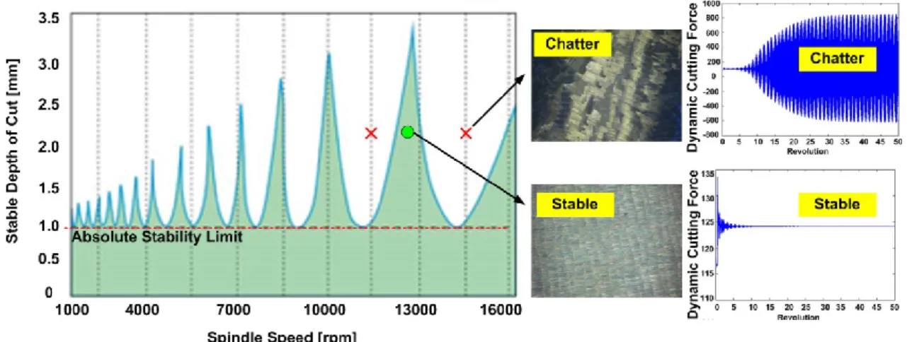
Figure 1.2. Delay between the vibration marks of the tooth j and tooth j+1. If the milling or turning cutting parameters are selected properly, chatter free material removal rate may be increased. In order to determine optimal cutting parameters, process models and simulations can be used to predict cutting forces and machine tool vibrations. Stability diagrams in milling and turning operations are widely used to predict the stability limits and avoid chatter. Example stability diagram can be seen in Figure 1.3. Any combination of depth of cut and spindle speed above the stability limits results chatter in the process. Stability pockets (lobes) provide the advantage of high depth of cuts without chatter occurrence. Generally, stability pockets are impractical at low speeds and absolute stability limit is preferred as the limiting depth. On the other hand, high MRR is possible only at the high spindle speed values where the stability pockets are extended. Although the high speeds provide high stability limits, it may not be generalized. As shown in Figure 1.3, selection of 2 mm depth of cut at 14500 rpm results chatter in the process whereas the 12800 rpm provides stable cutting conditions. Also, sample surface finish and dynamic cutting force plots are illustrated both for the chatter and stable cutting conditions. Poor surface finish and increased cutting forces are observed in chatter whereas good surface quality can be achieved in stable cutting condition.
3
Figure 1.3. Stability diagram and surface photo and variation of cutting forces at stable and unstable conditions.
Special milling tools such as variable pitch and helix geometry tools are employed widely to reduce the cutting forces and increase the chatter stability. Variable tooth spacing between the adjacent teeth of the tool may alter the phase difference between the inner and outer modulations on the surface and suppress the regeneration effect if they are designed or selected properly. Also, variable tool geometry introduces multiple delays into the system. For a regular milling tool, the delay is constant between the adjacent teeth of the tool. However for a variable pitch milling tool, the number of time delays can be at most equal to the number of teeth. For example a variable pitch tool having pitch angles with constant helix, the number of time delay is two. On the other hand, if both variable pitch and variable helix tool is used, number of time delays increases. Hence, the chatter stability of variable tool geometry tools is a multi-delay system and has complex solution compared to the regular end milling tools.
On the other hand, design of variable tooth spacing milling tools are mainly based on try-and-error method. There have been many works that analyze and model the chatter stability of variable tools but in none of these studies the design of the optimum tool geometry is considered. The existing models can be used to determine the best cutting condition for a given tool. However, in industry, cutting parameters are almost fixed due to various reasons in many applications. For example, the cutting speed may not be changed substantially due to some limitations which are explained in next sections. Hence, the optimum tool geometry should be determined for given cutting conditions in an application.
4
Simultaneous machining operations have also been continuing to spread in various sectors due to diverse advantages they offer. First of all, processing the part with more than one cutting tool obviously increases the productivity and reduces production time. Furthermore, employing two cutting tools may cancel out the dynamics cutting forces, and thus vibrations increasing stability limits substantially. Parallel turning and parallel milling are two common examples of the simultaneous machining operations. Parallel milling involves more than one milling tool cutting the same or different surface at the same time. In Figure 1.4geometry of the parallel milling operations are demonstrated.
Figure 1.4. Sample demonstration of parallel milling operation.
If the correct process parameters are used, parallel milling has the potential to increase productivity substantially by keeping or further increasing the part quality. On the other hand, as in the conventional milling operations, chatter vibrations may limit the full potential of the operation. Hence, dynamics of parallel milling operations should be investigated to determine proper cutting parameters. Optimum cutting conditions for a given process should be identified to increase productivity. On the other hand, due to existence of two milling tools and different spindle speeds, there may be multiple delays in the system as well. Also, angular offset between the cutting teeth of the tools provides additional delay terms to the chatter stability formulation of parallel milling operations.
Similar to parallel milling, parallel turning operations involve more than one cutting tool removing material from the same surface simultaneously. As in the parallel milling, existence of additional cutting tool may provide higher productivity and suppress the chatter vibrations if the cutting parameters are set properly. Figure 1.5 shows the geometry of the parallel turning operation [2].
5
Figure 1.5. Demonstration of parallel turning operation.
In this study, dynamics and chatter stability of multi delay systems are investigated. Chatter stability of the multi delay systems are more complex compared to the standard chatter stability solutions in milling and turning due to existence of additional delay at the system.
As an example of multi delay systems, variable tooth spacing tools and parallel milling operations are examined. Optimum variable tooth geometry is determined by considering the chatter stability of operation. High performance cutting conditions are found for a given cutting condition. Also, dynamics and chatter stability of the parallel milling operations are investigated and an analytical solution methodology in frequency method is proposed. Optimization studies have been concluded to achieve high stability limits. Finally, even there is a single delay in the system, chatter stability of the parallel turning operations are explained briefly and optimum tool geometry and properties are identified to achieve high chatter free stability limits. Optimization studies are conducted by using frequency domain model and verified by time domain model. For the first time in the literature, a design methodology that provides the optimum variable tool geometry is proposed for the variable tooth spacing milling tools. Without doing many and long optimization simulations, the optimum tool geometry configuration can be found by using the proposed new design method for a given cutting condition.
6
Also, a new analytical solution methodology for the chatter stability of parallel milling operations in frequency domain is provided. Furthermore, cutting parameters of the parallel milling operation that provides higher stability limits are optimized for the first time in the literature. Similar to the parallel milling operations, optimum cutting conditions for the parallel turning operations are determined.
1.1. Organization of the Thesis
The thesis organized as follows;
In chapter 2, first chatter stability of the variable tooth spacing milling tools is explained. Then optimization studies are performed by using Single Frequency Averaging Method. Optimum variable tool geometries are found for a given cutting condition and simulation results are verified by experiments. Finally, a design methodology that determines the optimum variable tool geometry is proposed.
In chapter 3, chatter stability of parallel milling operations is investigated in the frequency domain. Stability diagrams are generated for different cutting conditions and process parameters. Time domain verification of the frequency domain results is provided. Effects of workpiece dynamics on the chatter stability of parallel milling are studied in detail. Moreover, high performance machining conditions are identified by optimization studies and results are verified by experimental tests.
In chapter 4, dynamics and chatter stability of parallel turning operations are explained briefly and mostly concentrated on the optimization of dynamic properties of cutters. Two different methods are used in the optimization studies. Both methods alter the dynamic properties of the tools. Optimum dynamic cutter properties are identified in frequency domain model and verified with time domain model.
In chapter 5, conclusions obtained from this study are presented briefly and some possible improvements for future works are proposed.
7 1.2. Literature Survey
Dynamics and stability of machining have been studied in detail in many works. The theory of chatter in machining was first introduced by Tobias and Fishwick [3] and Tlusty and Polacek [4]. They demonstrated the coupling between the cutting forces and dynamic displacements and estimated the chatter stability limits. Tlusty and İsmail [5] carried out time domain simulations and acquired more accurate results for the stability limits by including the basic nonlinearity in cutting which is the loss of contact between the cutting tool and the material. Altintas and Budak [6] presented an analytical method for the stability of milling which can be used to generate stability diagrams in frequency domain very efficiently. Added lobes in milling due to flip bifurcations have been presented by several authors [7], [8].
Cutting tools with variable helix and variable pitch angles can be used for improving the stability of the milling process. Variation in the tooth spacing alters the delay in the cutting system disturbing regeneration mechanism. The effectiveness of variable pitch cutters in suppressing chatter vibrations in milling was first demonstrated by Slavicek [9]. He assumed a rectilinear tool motion for the cutting teeth, and applied the orthogonal stability theory to irregular tooth pitch. By assuming an alternating pitch variation, he obtained a stability limit expression as a function of the variation in the pitch. Opitz et al. [10] considered milling tool rotation using average directional factors. Their experimental results and predictions showed significant increase in the stability limit using cutters with alternating pitch. Vanherck [11] considered different pitch variation patterns in the analysis by assuming rectilinear tool motion. His computer simulations showed the effect of pitch variation on stability limit. Tlusty et al. [12] analyzed the stability of milling cutters with special geometries such as irregular pitch or serrated edges using numerical simulations. These studies mainly concentrated on the effect of pitch variation on the stability limit; however they do not address the cutting tool design, i.e. determination of the optimal pitch variation. Altintas et al. [13] adapted the analytical milling stability model to the case of variable pitch cutters which can be used more practically to analyze the stability of variable pitch cutters. Later, Budak proposed an optimization methodology [14] for design of variable pitch tools considering the chatter frequency and spindle speeds. He showed that the selection of pitch variation is very critical for increasing chatter stability limits. Olgac and Sipahi
8
[15] developed an optimization model for similar tools by analyzing the dynamic characteristic equation of the system using cluster treatment method. Later, Ferry [16] developed a mechanical and dynamical model to predict stable cutting regions for serrated variable pitch cutting tools using the Nyquist criteria. Turner et al. [17] obtained coherent results for low radial cutting cases by applying the method [14] developed for variable pitch cutters to variable helix cutters. Zatarain et al. [18] investigated the effect of helix angle on the chatter stability for low radial cutting conditions and concluded that flip bifurcation or period doubling effects should be also considered for low radial cutting conditions where cutting is very interrupted. Also, Sims et al. [19]-[20] investigated the chatter stability of variable helix and variable pitch cutters analytically, and proposed an optimization methodology by comparing three different modeling approaches, i.e. discretization [21],[22], time averaged semi-discretization with similar assumptions to Budak’s model [14], and temporal-finite element method (TFEA) [20]. Finally, Dombovari and Stepan investigated the effect of the helix angle variation on the chatter stability by semi-discretization method [23]. Dynamics and stability of parallel milling, on the other hand, has been studied very little. Ozturk and Budak [24] have simulated the dynamics of parallel milling in time domain and generated stability diagrams for various cutting conditions. Brecher and Trofimov [25] also used time domain simulation method and showed the effect of relative angular position offset and spindle speed on the stable depth of cut. Shamoto [26] posed the suppression of chatter in simultaneous milling by speed difference. Dynamics and chatter stability of conventional single turning is have been investigated by many researches decades. Although there have been many work done on chatter stability of single turning operations, there are few studies about the stability of parallel turning operations. Lazoglu, et. al. [27]formulated the parallel turning operation in time domain where each tool cuts a different surface. They showed that working the cutting tools simultaneously reduce the stability limits of each other. Later, Ozdoganlar and Endres [28] developed a stability model of parallel turning operations but only applicable to symmetric systems only. They verified the developed formulation by means of experiments. After that, Tang, et. al. [29] predicted the cutting forces, spindle power and tool life in parallel turning operations. However, they have not taken into consideration the chatter stability of the parallel turning. In recent years, Ozturk and Budak [2]solved the chatter stability of parallel turning operation in both frequency and
9
time domains. They modeled the chatter stability of two different cutting conditions in parallel turning. In the first case, the cutting tools located at the same turret and cut the same workpiece simultaneously. The dynamic coupling was between the tools since they were clamped on the same turret. In the second case, turning tools were clamped of different and independent turrets on the parallel turning machine tool. In this case, there was no direct coupling between the tools but they were dynamically coupled through the workpiece. They also have verified the frequency and time domain solutions by experimental studies.
Design of optimum variable tool geometry has never been investigated in the literature so far. All the previous works were aimed to generate stability diagrams for a given variable tooth spacing tool. However, it is significant to design optimum variable tool geometry for a given cutting condition. In this study, design methodology that provides optimum tool geometry for the given cutting conditions is proposed to fill the gap in the literature in this regard.
In parallel milling operations, frequency domain model has never been investigated in the literature before. The previous works obtained a solution methodology which is in time domain which is time consuming and not provide a stability diagram at a time. Hence a new frequency domain model is introduced in this thesis to fill the gap in the literature.
Finally, determining of optimum dynamic properties of cutters in parallel turning has never been worked so far. In this respect, optimum dynamic properties of cutters are identified for parallel turning operations.
10 CHAPTER 2
CHATTER STABILITY OF VARIABLE PITCH/HELIX TOOLS AND DESIGN OF OPTIMUM VARIABLE TOOL GEOMETRY FOR INCREASED STABILITY
Machining is based on removing material from a bulk or a near net shape part in the form of chips using shearing mechanism involving high strains and strain rates. Manufacturing industry today increasingly demands shorter lead times, competitive prices and higher product quality. In order to fulfill these requirements a milling operation should achieve high productivity with increased MRRs (Material Removal Rate) and tight dimensional, form and surface tolerances under stable cutting conditions. Reduced cutting forces and increased chatter stability can increase productivity and part quality substantially. Special milling tools can be very effective for reduced cutting forces and increased stability when they are designed or selected properly. Cutting tools with variable helix and variable pitch angles can be used for improving the stability of the milling process. Suppressing the delay and chatter vibrations in the dynamic cutting system, make the variable milling tools prior alternative over the regular milling tools.
In some industries, such as aerospace and defense, titanium and nickel alloys that have low machinability, are commonly used. High spindle speeds that provide high stability limits cannot be achieved and stability pockets may not be utilized due to the low machinability of these materials which usually have to be machined at slow speeds. Furthermore, machine tool limitations such as spindle speed as well as power and torque (especially at high speeds) also impose limitations on utilization of deep stability pockets usually available at high cutting speeds. Finally, unbalance in the spindle or
11
system becomes noxiously high at high spindle speeds. Variable tooth spacing tools (variable pitch/helix) can be used for such cases.
In this chapter, chatter stability models for variable pitch and helix tools are simply explained by concentrating on the optimization of variable tooth spacing to develop a design methodology.
2.1. Description of Variable Geometry Milling Tools
Variable tooth spacing milling tools can be classified in three categories. First one is the variable pitch milling tool which have non uniform pitch angles between adjacent teeth. Second type is the variable helix milling tools and helix angles of each tool are not uniform. Last type is the hybrid version of the variable pitch and variable helix milling tools where the both pitch and helix angles are non-uniform. There are also different types of variations of the variable geometry milling tools. Alternate, linear and sinusoidal variations are commonly used in industry.
In Figure 2.1, illustration of tool geometry of variable pitch tool can be seen. Pitch angles between the teeth are different as for each tooth.
Figure 2.1. Tool geometry of variable pitch tool.
12
Figure 2.2. Tool geometry of variable helix tool.
In this study, two common variation patterns are considered for both pitch angle and helix angle distribution, which are linear and alternating. For both cases in non-uniform pitch distribution, a pitch angle variation measure, ΔP, is introduced and the initial pitch angle is found as follows [14];
( ) ( ) }Linear (2.1) { evenodd ∑(( ) ) } Alternating (2.2)
For example, variable pitch alternate variation tool with 2 degrees of variation (ΔP) has the pitch angles as - - - . In the same way, the variable pitch linear variation tool with 2 degrees of variation has the pitch angles as - - - . The same example can be expanded for the variable helix alternate and linear variation tools. For the helix angle variation for both alternating and linear distributions, the helix variation measure is denoted as ΔH. This variation measure has to be tuned to assure no crossing occurs between consecutive teeth due to the lag effect of both helix and pitch variation. This constraint is noted as;
13
Figure 2.3. Unfolded tool geometry and variable flute parameters.
2.2. Chatter Stability of Variable Helix and Pitch Milling Tools
Due to the geometry of variable pitch and helix milling tools, dynamic cutting system is affected by multiple delays which are originated from the different pitch and helix angle variations of the teeth. Therefore, chatter stability of variable tooth geometry tools is more complex compared to the regular end mills. Stability models for the solution of the variable tool geometry are investigated in a lot of works [30], [31]. Two methods that mentioned in this study are the “Semi-Discretization Method” and “Single Frequency Averaging Method”. In this study, stability methods are explained simply and by using one of these methods, optimization and design of variable tool geometries have been concluded.
2.2.1. Semi-Discretization Method
Chatter stability of variable pitch and helix tools can be solved by using semi-discretization method and a lot of works have been concluded. Semi-semi-discretization method is used for the stability analysis of linear – time periodic delay differential equations [21].
First step to solve the stability is the formulation of the governing equation. The stability of milling operations is dependent on the dynamically varying chip thickness which is a function of both current and past vibration marks left on the cut surface. Milling system is modeled with two orthogonal degrees of freedom in x and y process directions. Dynamic chip thickness and orthogonal degrees of freedom are illustrated in Figure 2.4.
14
Figure 2.4. Dynamic chip thickness and two orthogonal degrees of freedom. Equations of motion in x and y process directions are given as follows:
̈( ) ̇( ) ( ) ( )
(2.4)
̈( ) ̇( ) ( ) ( )
where , , , , , represent the natural frequencies, damping ratios and
modal masses of the most dominant vibration modes of the system in x and y directions. In order to take the variable pitch and helix angles into account, the cutting tool is divided into axial disc elements along the tool axis. System equations are written as follows before they are transformed into the first order:
{ ̈( ) ̈( ) ̇( ) ( ) ̇( ) ( )} ∑ [[ ( )] [ ( ) ( ) ( ) ( )]] (2.5)
( ) matrix consists of directional coefficients which are grouped according to their delay values. This is because the variable tool geometry introduces multiple delays into the system. The number of different delays in the system is represented with . The
stability analysis of the governing delay differential equation with time-periodic coefficient matrices is done with First Order Semi-Discretization Method (SDM) [21]. In order to analyze the stability of Equation 2.5, the eigenvalues of the infinite-dimensional monodromy matrix is required [21]. With the First Order SDM, the infinite dimensional monodromy matrix is approximated with a finite dimensional one. Then, the stability of the system is analyzed with the approximate monodromy matrix according to the Floquet Theory as stated in [21]. One of the main ideas which
semi-15
discretization method is based on is to divide the principle period T of the system into p discrete time intervals.
(2.6)
where is the principle period resolution, is the length of discrete time intervals. Stability of the system is analyzed with the eigenvalues of the resulting matrix according to the Floquet theory. If the largest complex eigenvalue of the monodromy matrix has an absolute value bigger than 1 the system is unstable, if it is equal to 1 the system is on the stability boundary or if it is less than 1 than the system is stable.
2.2.2. Single Frequency Averaging Method
The dynamic milling expression can be written for a regular milling tool as [6];
{ ( )} [ ( )]{ ( )} (2.7)
where is axial depth of cut, is the tangential cutting force coefficient and consists of the directional coefficients and is a periodic at tooth passing frequency
. Hence it can be expanded into Fourier series.
On the other hand, number of harmonics of the tooth passing frequency ( ) is important to solving the stability equation. If the number of harmonics of the tooth passing frequency is considered as zero which is the most simplistic approximation, the average component of the Fourier series expansion is taken into account and the equation (6) becomes;
{ ( )} [ ]{ ( )} (2.8)
where is the time invariant directional cutting coefficient matrix. This solution of the stability equation is known as “Single Frequency Solution” and applicable to the most of the stability problems in milling and turning operations.
However, the single frequency solution may not be satisfied for some cutting conditions where the width of the cut is small and the milling forces are highly intermittent [8]. In such cases, harmonic components of the tooth passing frequencies have strong
16
influences in addition to the average value. Hence stability results may not satisfy the physical analysis. So that, solution to the stability equation (Equation 2.8), must be considered as the higher harmonics of the tooth passing frequency in addition to the average Fourier series expansion component. This solution is called as “Multi Frequency Solution”. In this study, “Single Frequency Method” is applied to the stability problem and the most dominant mode of the tool is considered.
The stability of a regular milling tool depends on the phase difference between the inner and outer modulations on the surface and the time delay between the consecutive teeth is always constant since the pitch angles are uniform. Since the time delay does not vary along the cutting edge, the regeneration term equals to ( ) and constant at
every axial elevation. However, for the variable tooth spacing tools such as variable pitch and helix tools, the regeneration term for the jth cutting edge at elevation z can be written considering the separation angle as follows [31]:
( ) ( ) (2.9)
where ( ) is the time delay and can be written considering the separation angle as follows:
( ) ( ) (2.10)
The chatter stability model is formed as an eigenvalue problem where the closed loop system is described in terms of dynamic chip thickness [31]. Considering the regenerative effect, the dynamic chip thickness and force components are defined in the frequency domain as;
[ ( ) ( ) ( ) ] ( ) (∑ ( ) ) ( ) [ ( ) ( ) ( ) ] (2.11)
where (directional coefficient matrix) is the first term of the Fourier series expansion and consists of the multiple delays (m number) in the system. Also, is the length of the axial slice and ( ) is the transfer function of the tools. Equation 2.11 is an eigenvalue problem and the stability limit can be calculated for the given condition. In order to obtain the chatter stability diagram, an iterative method is followed. Due to the varying delay function, for a chosen spindle speed the limiting depth of cut is sought
17
by sweeping a range of frequencies. The flowchart of the iterative method is explained inFigure 2.5.
Figure 2.5. Flowchart of the iterative solution methodology.
In the optimization and design of optimum variable tool geometry studies, single frequency averaging method has been used. The paramount factor in this choice is the robustness and flexibility of the solution methodology that can be applied for distinct variable tooth spacing tool geometries.
2.3. Optimization of Variable Helix & Pitch Milling Tools
Selection of pitch and helix angle variation has strong impact on milling process stability. If the variations are not selected properly, the desired improvements may not be achieved. On the other hand, chatter stability limits can be maximized by using optimum pitch and helix variations on special milling tools. This can be done by using stability simulations based on the formulation and the procedure presented in the previous section as it will be demonstrated in this part of the thesis. Up to now, a lot work has been done on the modeling and analysis of chatter stability of for variable pitch and helix tools. These works were aimed to generate stability diagrams for a given variable geometry milling tool. On the other hand, in most industries such as aerospace and die and mold industries, the cutting conditions are mostly fixed due to quality, cost
18
and productivity requirements. For these cases, the cutting conditions may not be varied substantially. Hence, an optimum variable pitch or helix tool geometry should be identified for given cutting conditions in order to maximize stability in that range. Therefore, the main objective of the optimization study in this thesis is finding the optimum tool geometry that provides maximum chatter free cutting depth for a given condition. For alternating and linear variations of variable pitch and helix milling tools, optimum pitch and helix angles are sought using simulations. It is demonstrated that the stability limits can be increased substantially by simply using the optimal variations on the tools. Chatter tests are conducted to verify predictions by evaluating sound data and surface photos. Experimental results show relatively good agreement with the simulations.
2.3.1. Chatter Stability Simulations
Simulations were carried out for various pitch and helix variations in order to determine the optimal values and Matlab 2008© is used. In all simulations, a milling tool with 12 mm diameter and 4 flutes was considered. Fluted and overhang lengths of the tool are 28 mm and 35 mm, respectively. Radial depth of cut is 3 mm where the feed is 0.05 mm/rev*tooth. The milling cutter performs downmilling operation on an Al7075 test block. Modal parameters of the tools that were used in simulations and experiments are listed in Table 2.1
Table 2.1. Modal parameters of the variable tooth spacing milling tools.
Tool Code Direction Frequency [Hz] Natural Modal Stiffness [N/m] Modal Damping [%]
Tool 1 Xx 3374 1.37e+7 1.187
Yy 3360 1.35e+7 1.097
Tool 2 Xx 3994 3.89e+7 1.218
Yy 3989 2.85e+7 1.140
Also the variations of the helix and pitch variations of the tools are listed in Table 2.2as follows:
19
Table 2.2. Cutting flute parameters for custom made variable tools.
Tool Code Helix Angle [°] Variation Type Pitch Angles
Tool 1 30-33-30-33 Alternate 90-90-90-90
Tool 2 30-32-34-36 Linear 90-90-90-90
In the simulations, spindle speed range of 3000 to 4000 rpm was considered. Pitch and helix angle variation amount of 0° and 10° was considered with increments of 0.1°. For each pitch or helix variation amount stable depth of cut at a given spindle speed is calculated, and considering different spindle speeds 3D chatter stability diagrams are constructed. Variation of the chatter frequency with the helix and pitch variations is also considered and shown.
2.3.1.1. Optimization of Variable Helix Alternate Tool
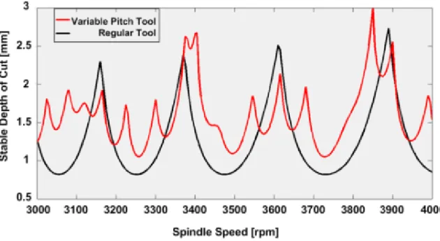
In the case of alternating helix tools, separation angle between consecutive teeth varies alternatingly for instance, 30°-35°-30°-35° for a 4-fluted milling tool where the variation is 5°. Stability diagrams for different values of variation in helix angle are shown in Figure 2.6. In the optimization simulations, dynamics properties of first tool (Tool 1) are used (see Table 2.1). The effect of the helix angle on the stability limit variation can easily be seen by evaluating the 3D stability diagram given in the figure. For this case, the optimum alternating helix variation is found as 1o at 3900 rpm where the maximum stable depth of cut is increased to 3.214 mm compared to the regular end mill which has the highest limit at 3900 rpm and 2.7 mm.
20
Figure 2.6. Stability diagrams vs. variation in the helix angle for a alternating helix milling tool.
For the optimal tool, the stability diagram is constructed and compared with a non-variable, i.e. regular, tool for the same dynamic and cutting conditions in Figure 2.7. It can be seen from the figure that the absolute stability limit is increased by %60 by using the optimal tool.
Figure 2.7. Stability diagrams for regular and variable helix tool with optimal variation. Variable pitch or helix tools change the chatter stability behavior as they affect the phase, or delay, between the outer and inner modulation in a milling process. In general,
21
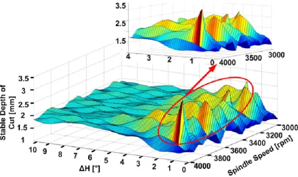
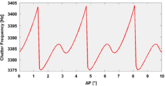
the stability limit can be maximized by minimizing or eliminating the delay. This is done by selecting a favorable speed based on stability diagrams for standard milling tools. In case of special geometry milling tools, this can also be done by the variation of the teeth spacing. Since the delay in dynamic cutting depends on cutting speed and chatter frequency, one should expect a strong influence of the teeth spacing helix angles on chatter stability which is also demonstrated inFigure 2.8. The delay or phase can be related to the pitch variation for its cancellation. On the other hand, chatter frequency also varies due to the alterations in the teeth spacing which makes the selection of optimal pitch or helix variations difficult. As an example, variation of the chatter frequency with the helix angle variation at 3900 rpm is shown inFigure 2.8. The natural frequency of the tool is 3370 Hz and the peak value of the chatter frequency occurs at the optimum helix angle.
Figure 2.8. Variation of chatter frequency with helix angle alteration. 2.3.1.2. Optimization of Variable Helix Linear Variation Tool
Similar to the case of alternating helix, linear helix angle variation can also be optimized using stability simulations. The same tool geometry and process parameters are used while using the modal parameters of the Tool 2 (Table 2.1). The simulation results are shown inFigure 2.9.
22
Figure 2.9. Stability diagrams vs. linear variation in the helix angle.
It can be seen that after 3.4° linear helix angle variation measure (ΔH), the flute crossing is occurred in the process.(seeFigure 2.10.)
23
The optimum helix angles can be found out as 1.8° for 3800 rpm and 1.7° for 3200 rpm from the simulation results. Figure 2.11, shows the stability diagrams for optimal linearly varying helix angle and standard tools.
Figure 2.11. Comparison of regular and optimum variable helix with linear variation tool.
It can be seen that, both the absolute and peak stability limits are increased substantially (about three times) using the optimal varition in the helix angle.
Similar to the alternating helix tool, the chatter frequency varies with the helix angle variation in this case as well, as shown inFigure 2.12.
Figure 2.12. Variation of chatter frequency with linear helix angle variation measure. It is important to note that the natural frequency of the tool is 3994 Hz and the peak value of the chatter frequency corresponds the point of optimum helix angle variation.
24
This means that the highest stability limit can be achieved by minimizing the delay in the system at that helix variation angle.
2.3.1.3. Optimization of Variable Pitch Alternate Variation Tool
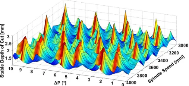
Variable pitch end mills have non-constant spacing between adjacent teeth. Similar to the variable helix optimization, variable pitch milling tools’ optimization was also performed. The same cutting parameters, tool geometries and modal parameters are used in the simulations. Then, the optimal pitch angle variations that provide the highest chatter free depth of cuts were determined for a range of spindle speeds. The effect of the pitch angle variation can easily be seen by evaluating the 3D stability diagram given in theFigure 2.13.
Figure 2.13. Variation of the stable depth of cut with spindle speed and alternating pitch angle.
As seen from the figure, the optimum alternating pitch variations appear at many points for each spindle speed. The maximum stable depth of cut which is about 2.92 mm occurs at 8.1° for 3850 rpm. On the other hand, it is important to note that there are several ΔP and spindle speed pairs that provide closer depths to the optimum (maximum) stable depth of cut possible. In Figure 2.14, comparison of the stability diagrams between the regular and alternating pitch tool can be seen.
25
Figure 2.14. Comparison of regular and optimum alternatingly variable pitch tool. Absolute stability limit is increased by about %25 compared to the regular tool. However, in some certain stability pockets, the stable depth of cut decreases with the introduction of pitch variation. In Figure 2.15, crossection view of the 3D surface (Figure 12) at 3850 rpm can be seen.
Figure 2.15. Variation of stable depth of cut with pitch variation amount
It is clearly seen from Figure 2.15 that there are multiple optimal pitch variation angles which repeat in a regular manner. Variation of the chatter frequency with the pitch angle variation at 3850 rpm is also shown in Figure 2.16. As in the optimization of variable helix tools, the maximum chatter frequency occurs at the optimum pitch angle variation that provides maximum stable depth of cut. This is again due to the minimized delay in the system at those conditions.
26
Figure 2.16. Variation of chatter frequency with alternatingly pitch angle variation amount.
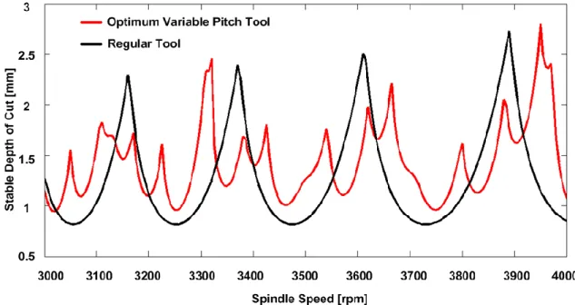
2.3.1.4. Optimization of Variable Pitch Linear Variation Tool
Similar to the variable pitch alternate variation tool optimization, optimization of variable pitch linear variation tool was also performed. The same tool geometry and modal parameters are used as previous variable pitch optimization. Then, the optimal pitch angle variations that provide the highest chatter free depth of cuts were determined for a range of spindle speeds. The effect of the pitch angle variation can easily be seen by evaluating the 3D stability diagram given in theFigure 2.17
Figure 2.17. Variation of the stable depth of cut with spindle speed and linear pitch angle.
27
As in the variable pitch alternate variation tool case, there are multiple optimum points that provide maximum stable depth of cut limits. Numerically, optimum point corresponds to the combination of 4.1° of pitch variation and 3950 rpm spindle speed. On the other hand, it is important to note that there are several ΔP and spindle speed pairs that provide closer depths to the optimum (maximum) stable depth of cut possible. Figure 2.18 shows the comparison of the optimum variable pitch tool with the regular tool.
Figure 2.18. Comparison of optimum variable linearly varying pitch tool and regular tool.
Absolute stability limit is increased by % 20 compared to regular tools. On the other hand, in some stability lobes, stable depth of cut value is decreased with the introduction of pitch variation.
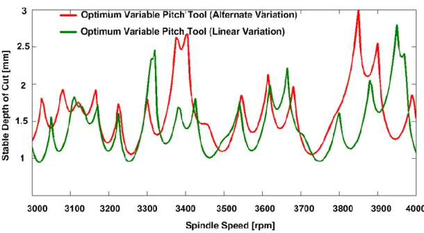
Comparing the variable pitch tools as alternate and linear variation for the same cutting geometry and modal data helps us to see the difference between these variations. In Figure 2.19 comparison of the optimum variable pitch alternate variation and variable pitch linear variation tools can be seen.
28
Figure 2.19. Comparison of alternate and linear variations for variable pitch tool. It is hard to say which tool is the best one. Absolute stability limits of both variations are almost the same and alternate variation variable pitch tool has slightly higher stability limits for some stability pockets.
On the other hand, the significant point is the optimized cutting conditions of each tool. Alternate variation tool was designed at 3850 rpm of spindle speed where linearly varying variable pitch tool was designed at 3950 rpm. It can be easily seen that, alternately varying tool is effective at its optimized condition which is 3850 rpm and linearly varying variable pitch tool is also more effective than the alternately varying tool at 3950 rpm. For alternately varying tool, stability limit is about 3 mm at 3850 rpm where the stability limit of linearly varying tool is only about 1.25 mm. Nevertheless, linearly varying variable pitch tool has 2.8 mm stable depth of cut at 3950 rpm but alternately varying variable pitch tool has the stability limit of 1.26 mm at the same cutting condition.
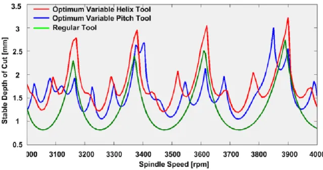
Finally, for the same tool geometry, modal parameters and the cutting conditions, it can be concluded that variable helix tools are superior to the variable pitch tools for alternating variation. Stable depth of cut for the variable helix tool was calculated as 3.214 mm which is about %10 higher than the limit for the variable pitch tool (2.9 mm). The comparison of both optimum variable helix tool, optimum variable pitch tool and the regular flat end mill are shown inFigure 2.20.
29
Figure 2.20. Comparison of optimum variable helix, pitch and regular end mill tools. 2.3.2. Experimental Verifications
Experiments were performed in Mazak Nexus 510C-II machine tool for the simulated cases. Different spindle speeds and axial depth of cuts for two milling tools are used and the stability of the process is evaluated. Two different variable helix tools with alternating and linear variations and constant pitch angles at the tip of the tools are used in the chatter tests (seeTable 2.2).
Since the helix variations of both tools are known, the stability diagrams can be generated easily by following the procedure given in section 3. In order to be able to see the effect of the helix variation on the stability limits, stability diagrams for the regular, i.e. non-variable tool, are also generated.
In the experiments, several axial depth of cuts at different spindle speeds for both linearly varying and alternating helix tools are used, and the process status is identified as stable, marginal and chatter. Microphone and laser sensor are used to detect chatter. Also, the surface photos of each test are evaluated to confirm the stable and unstable regions. Experimental set up can be seen inFigure 2.21.
30
Figure 2.21. Test setup.
Experimental results for the first tool (alternating variation) are shown in Figure 2.22 together with the predictions. The sound spectrum and the machined surface pictures of point A (stable) and point B (unstable) are given in Figure 2.23 and Figure 2.24. Point A is in the stable zone as can be seen from the sound spectrum which shows no dominant frequency. Point B, on the other hand, is in the unstable region, and chatter is observed both in sound spectrum and the machined surface picture. As can be seen from the figure, the chatter frequency is at 3360 Hz and the surface quality is poor.
Based on these comparisons it can be concluded that the experimental results have good agreement with the simulations.
31
Figure 2.23. Sound FFT and surface photo of point A.
Figure 2.24. Sound FFT and surface photo of point B.
Because of the relatively low spindle speeds and tightness of the stability pockets, it is hard to perform cutting operation in these lobes. Hence, absolute stability limits become more important and decisive. Absolute stability limit for the regular milling tool is about 0.8 mm whereas for the alternating helix tool it is 2 times higher.
For the second (linear helix variation) tool, experimental results are shown in Figure 2.25 together with the predictions. Different axial depth of cuts and spindle speeds were tested where sound and surface photos were also analyzed. Results are identified as stable, marginal stable and chatter and show good agreement with the simulations.
32
Figure 2.25. Stability diagram and test results for tool 2. 2.3.3. Effect of Radial Depth of Cut on Optimum Solution
Optimization studies have been done for one value of the radial depth of cut which is 3 mm for a 12 mm diameter end mill. At these conditions, comparisons of the variable pitch/helix and alternate/linear variations were also done. In the light of these simulations, one can identify the optimum tool and variation combination for the cutting operation. On the other hand, in order to be able to generalize the results to other conditions, different radial depth of cuts should be tried. In this section, comparisons of variable pitch/helix and alternate/linear variations for different radial immersions are made.
For the previous optimization simulations, 3 mm radial depth of cut value is used for all cases. For the alternate variation case, it has been shown that optimum designed variable helix tool is better than the optimum variable pitch tool. To generalize this rule, for a 12 mm diameter tool, radial depth of cut values are expanded into 1, 6 and 9 mm and it has been observed that the optimum variable helix tools with alternate variation still provides higher stability limits than the optimum variable pitch tool. Hence, it can be generalized that optimum designed variable helix alternate variation tools are always better than the optimum designed variable pitch alternate variation tool regardless of the radial immersion.
Similarly, optimum variable helix alternate variation tool provides higher stability limits than the optimum variable helix linear variation tool for the 3 mm radial depth of cut value. This situation is again generalized for different radial depth of cuts which are 1, 6
33
and 9 mm, and the optimum variable helix, alternate variation provides higher stability limits than the linear variation. So it can be concluded that alternate variation is better than the linear variation at every radial immersion condition for the optimum variable helix tools.
Finally, for the previous optimization studies, optimum variable pitch tools were compared for the alternate and linear variations and alternate variation was slightly provided higher stability limits for the 3 mm of radial depth of cut value. Moreover, it is expanded for the 1, 6 and 9 mm radial immersion values and it is observed that alternate variation still provides higher limits than the linear variation. Hence, it can be generalized that results of the optimization studies can be expanded for every radial immersion value in a similar way.
2.3.4. Design Methodology of Optimum Variable Tool Geometry
In the previous section, optimum tool geometry was determined for a given cutting condition through simulations. These simulations take long time to find the optimum pitch or helix variations. Determining the optimum pitch or helix variations by optimization simulations is the most reliable way but it can be computationally expensive. A design methodology would be very practical for industrial applications without losing time. Then, the main objective of this section is to develop a design method that gives the best tool geometry for a given cutting condition.
Investigation of the optimum tool geometry in the previous section where optimal pitch and helix variations were found is the first step of the design methodology. The relationship between the optimum variation and the minimization of the delay is the starting point of our design logic. Phase difference between the inner and outer modulations is expected to be equal to the corresponding delay generated by the optimal pitch or helix variations.
By taking this into consideration, optimum variations for the variable pitch tools are analyzed. Variable helix optimization studies are excluded because of the complexity of its delay system, i.e. the delay is variable along the axial depth due to changing pitch between successive cutting teeth. This means that, the phase difference at the bottom of the tool is not equal to the phase difference at any point of the tool along its axial depth of cut. One assumption would be to use an average phases along the axial depth of cut
34
but it is not guaranteed to provide reliable results. On the other hand, for variable pitch tools, there is only one phase difference between the successive teeth and it is the same all along the tool length. This allows us to analyze the optimum pitch variations and the phase difference in the system.
As stated before, analyzing of the optimum pitch variations is the starting point of the design methodology. The main aim of this analysis is to verify the relationship between the phase difference and optimum pitch variations.
Firstly, all optimum points at different spindle speeds and corresponding chatter frequencies are gathered from the optimization simulations by evaluating the 3D stability diagrams (Figure 2.13 and Figure 2.17). Also, optimum points at different radial depth of cut values are considered.
Secondly, for each of the optimum points gathered before, the length of a vibration wave is calculated by considering the spindle speed and chatter frequency at those points. Then, the equivalent wave length that corresponds the optimum pitch variation is calculated and denoted by the symbol of and shown inFigure 2.26.
Figure 2.26. Equivalent wave length corresponds optimum pitch variation.
Then, the phase difference between the inner and outer modulations of vibration waves is calculated and denoted by the symbol of and shown in Figure 2.27.