APPENDIX / ANHANG / ANNEXE
ALPHA ALTERNATOR
DIMENSIONS, INSTALLATION DRAWINGS AND CHARACTERISTICS
MASTERVOLT Snijdersbergweg 93, 1105 AN Amsterdam The Netherlands Tel.: +31-20-3422100 MASTERVOLT Snijdersbergweg 93, 1105 AN Amsterdam The Netherlands Tel.: +31-20-3422100
CONTENTS:
10000003207/021 DIMENSIONS ... 3
1.1 Dimensions Alpha alternator model 12/90 ... 3
1.2 Dimensions Alpha alternator models 12/130, 24/75 and 24/110 ... 4
1.3 Dimensions Alpha alternator model 24/150 ... 5
1.4 Dimensions Alpha Pro II regulator ... 6
2 INSTALLATION DRAWINGS ... 7
2.1 Alpha Alternator model 12/90 ... 7
2.2 Alpha Alternator models 12/130, 24/75 and 24/110 ... 8
2.3 Alpha Alternator model 24/150 ... 9
2.4 Standard Bosch alternator ... 10
2.5 Instruction for modification of standard Bosch alternators ... 11
2.6 Installation examples for Alpha alternator model 12/90 ... 12
2.7 Installation examples for Alpha alternator models 12/130, 24/75 and 24/110 ... 14
3 CHARACTERISTICS ... 15
3.1 Charge current versus RPM ... 15
4 ORDERING INFORMATION ... 16
4.1 Accessoires ... 16
4.2 Spare parts ... 16
1 DIMENSIONS
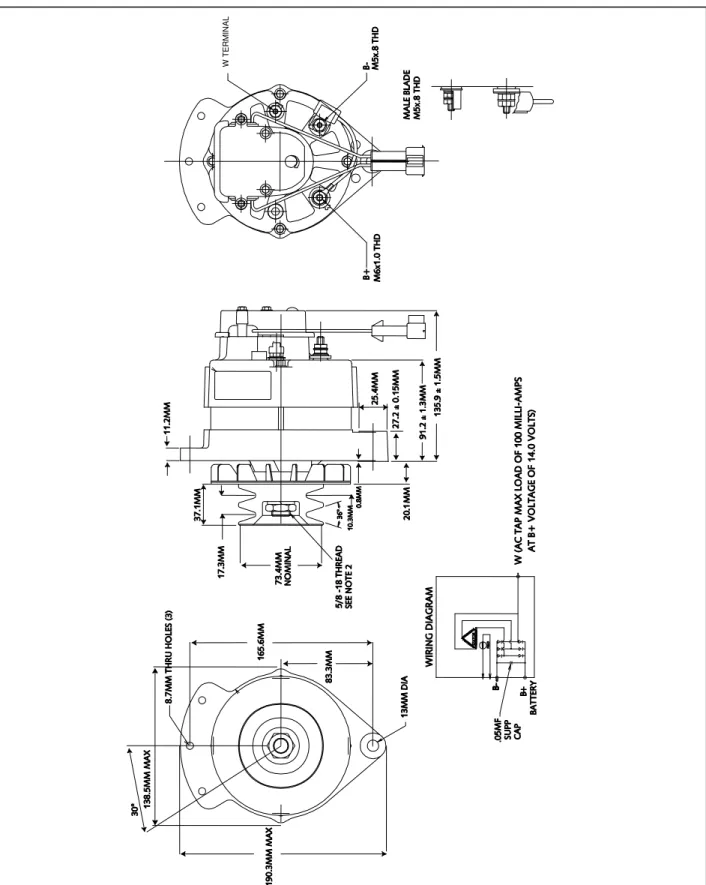
1.1 DIMENSIONS ALPHA ALTERNATOR MODEL 12/90
Figure A-1: dimensions Alpha alternator model 12/90 (enclosure A)
W T E R M IN A L
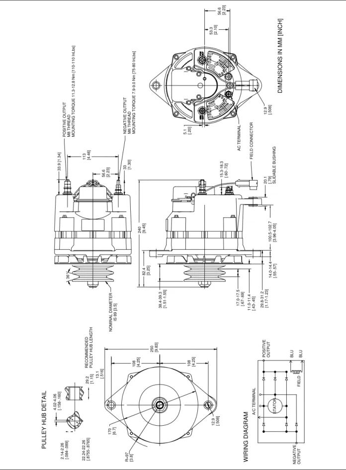
1.2 DIMENSIONS ALPHA ALTERNATOR MODELS 12/130, 24/75 AND 24/110
Figure A-2: dimensions Alpha alternator models 12/130, 24/75, 24/110 and 24/150 (enclosure B)
P O S IT IV E O U T P U T M 8 T H R E A D M O U N T IN G T O R Q U E 1 1 .3 -1 2 .8 N m [ 1 1 0 -1 1 0 I n L b s ] N E G A T IV E O U T P U T M 6 T H R E A D M O U N T IN G T O R Q U E 7 .9 -9 .0 N m [ 7 5 -8 0 I n L b s ] 3 3 .9 [ 1 .3 4 ] 3 3 [1.30 ] 5 6 .6 [2 .2 3 ] 1 1 3 [4 .4 6 ] 2 4 0 [9 .4 5 ] 8 2 .4 [3 .2 5 ] 3 8 .4 -3 9 .3 [1 .5 1 -1 .5 5 ] 1 0 8 [4 .2 5 ] 1 0 8 [4 .2 5 ] 2 5 0 [9 .8 3 ] 1 7 .0 -1 7 .5 [. 6 7 -. 6 9 ] 1 1 .0 -1 1 .4 [. 4 3 -. 4 5 ] 2 9 .8 -3 1 .2 [1 .1 7 -1 .2 3 ] 1 7 0 [6 .7 ] R = 9 7 [3 .8 ] 1 2 .9 [. 5 0 8 ] 1 3 .1 [. 5 1 6 ] 2 9 .2 [1 .1 5 ] 4 .0 2 -4 .0 6 [. 1 5 8 -. 1 6 0 ] R E C O M M E N D E D P U L L E Y H U B L E N G T H NOM IN A L D IA M E T E R IS 8 9 [ 3 .5 ] 2 .1 4 -2 .2 6 [. 0 8 4 -. 0 8 9 ] 2 2 .2 4 -2 2 .2 6 [. 8 7 5 5 -. 8 7 6 5 ] P U L L E Y H U B D E T A IL P O S IT IV E OUT P U T WIRING DIAGRAM A /C T E R M IN A L B L U B L U N E G A T IV E OUT P U T S T A T O R F IE L D F IE L D C O N N E C T O R A C T E R M IN A L 2 0 .1 [. 7 9 ] S L ID A B L E B U S H IN G 1 5 .3 -1 8 .3 [. 6 0 -. 7 2 ] 5 .1 [. 2 0 ] 1 2 .9 [. 5 0 8 ] 5 3 .3 [2 .1 0 ] 5 6 .6 [2 .2 3 ] 1 4 .0 -1 4 .4 [. 5 5 -. 5 7 ] 1 0 0 .5 -1 0 2 .7 [3 .9 6 -4 .0 5 ] 3 6 ° D IM E N S IO N S I N M M [ IN C H ]
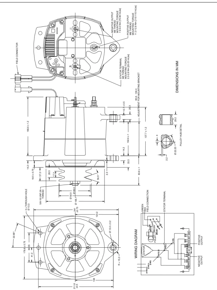
1.3 DIMENSIONS ALPHA ALTERNATOR MODEL 24/150
Figure A-3: dimensions Alpha alternator model 24/150 (enclosure C)
F IE L D C O N N E C T O R P O S IT IV E O U T P U T M 8 T H R E A D M O U N T IN G T O R Q U E 1 1 .3 -1 2 .8 N m [ 1 1 0 -1 1 0 I n L b s ] N E G A T IV E O U T P U T M 6 T H R E A D M O U N T IN G T O R Q U E 7 .9 -9 .0 N m [ 7 0 -8 0 I n L b s ] S T A T O R T E R M IN A L M 5 T H R E A D M O U N T IN G T O R Q U E 2 .3 -2 .8 N m [ 2 0 -2 5 I n L b s ] WIRING DIAGRAM D IM E N S IO N S I N M M 1 6 6 .6 ± 1 .2 1 4 .2 5 7 .3 1 8 .5 ± 0 .7 5 3 x T H R O U G H H O L E Ø 1 3 .3 2 8 .5 1 7 .3 2 2 .6 8 ° 5 6 .5 ° 1 7 8 .8 ± 0 .7 5 8 2 .5 5 4 1 .2 2 1 1 .8 ± 0 .5 Ø 1 3 .0 ± 0 .2 R = 1 5 .2 1 0 8 1 2 3 .2 2 .3 1 4 .2 3 3 .5 1 0 2 .6 ± 1 5 /8 -1 8 U N F -2 A T H R E A D 1 2 .7 ± 0 .5 1 3 7 .7 ± 1 .2 4 8 3 .8 ± 1 2 .2 2 0 .3 9 5 .8 1 0 0 .3 A D J U S T M E N T F O R M O U N T IN G B R A C K E T Ø 2 2 .2 5 2 9 .2 P U L L E Y H U B D E T A IL 2 4 1 ± 0 .7 3 Ø 1 6 6 .1 Ø 9 2 .0 Ø 8 9 .0 G R E E N R E D F IE L D C O N N E C T IO N S T A T O R T E R M IN A L S T A T O R P O S IT IV E OUT P U T N E G A T IV E OUT P U T
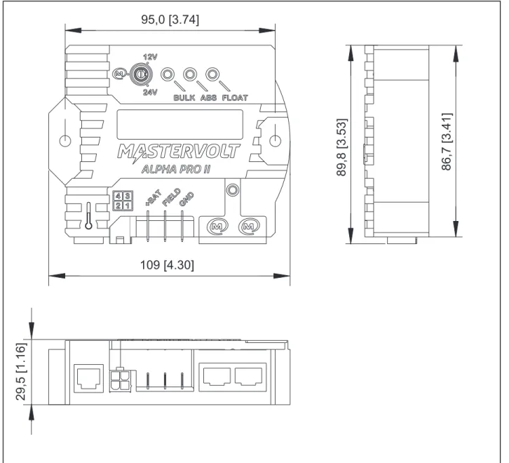
1.4 DIMENSIONS ALPHA PRO II REGULATOR
Figure A-5: dimensions of the Alpha Pro II regulator (all models)
95,0 [3.74]
109 [4.30]
29,5 [1.16]
2 INSTALLATION DRAWINGS
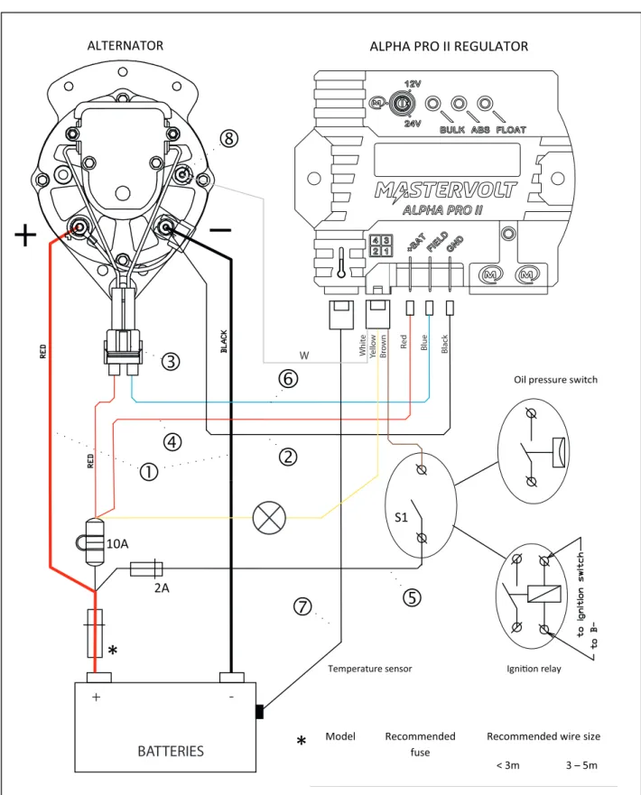
2.1 ALPHA ALTERNATOR MODEL 12/90
Figure A-6: Installation drawing Alpha alternator model 12/90
2A
Temperature sensor
10A ALTERNATOR Igni!on relay*
*
Model Recommended fuseRecommended wire size < 3m 3 – 5m
S1
Oil pressure switchALPHA PRO II REGULATOR
W hit e Y ello w Br o wn Red Blue Black
+
-BATTERIES
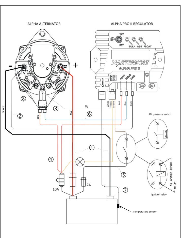
W2.2 ALPHA ALTERNATOR MODELS 12/130, 24/75 AND 24/110
Figure A-7: Installation drawing Alpha alternator models 12/130, 24/75 and 24/110
2A
Oil pressure switch
10A ALPHA ALTERNATOR
Igni!on relay
ALPHA PRO II REGULATOR
Temperature sensor
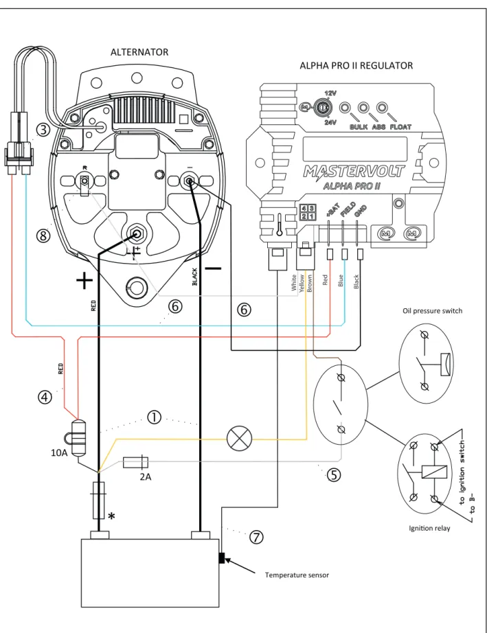
W hit e Y ello w Br o wn Red Blue Black W2.3 ALPHA ALTERNATOR MODEL 24/150
Figure A-8: Installation drawing Alpha alternator model 24/150
2A
10A ALTERNATOR*
Oil pressure switch
Igni!on relay
ALPHA PRO II REGULATOR
Temperature sensor
W hit e Y ello w Br o wn Red Blue Black2.4 STANDARD BOSCH ALTERNATOR
10A ALTERNATOR
*
2A
Oil pressure switchIgni!on relay
ALPHA PRO II REGULATOR
Temperature sensor
R ed Blue Black White Brown Yellow2.5 INSTRUCTION FOR MODIFICATION OF STANDARD BOSCH ALTERNATORS
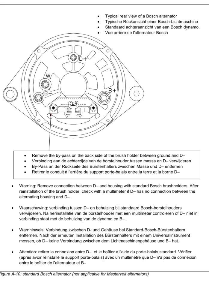
Figure A-10: standard Bosch alternator (not applicable for Mastervolt alternators)
• Typical rear view of a Bosch alternator
• Typische Rückansicht einer Bosch-Lichtmaschine • Standaard achteraanzicht van een Bosch dynamo. • Vue arrière de l'alternateur Bosch
• Warning: Remove connection between D– and housing with standard Bosch brushholders. After reinstallation of the brush holder, check with a multimeter if D– has no connection between the alternating housing and D–
• Waarschuwing: verbinding tussen D– en behuizing bij standaard Bosch-borstelhouders
verwijderen. Na herinstallatie van de borstelhouder met een multimeter controleren of D– niet in verbinding staat met de behuizing van de dynamo en B–..
• Warnhinweis: Verbindung zwischen D- und Gehäuse bei Standard-Bosch-Bürstenhaltern entfernen. Nach der erneuten Installation des Bürstenhalters mit einem Universalinstrument messen, ob D– keine Verbindung zwischen dem Lichtmaschinengehäuse und B– hat. • Attention: retirer la connexion entre D– et le boîtier à l'aide du porte-balais standard. Vérifier
(après avoir réinstallé le support porte-balais) avec un multimètre que D– n'a pas de connexion entre le boîtier de l'alternateur et B–
• Remove the by-pass on the back side of the brush holder between ground and D– • Verbinding aan de achterzijde van de borstelhouder tussen massa en D– verwijderen • By-Pass an der Rückseite des Bürstenhalters zwischen Masse und D– entfernen • Retirer le conduit à l'arrière du support porte-balais entre la terre et la borne D–
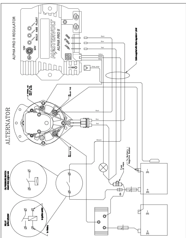
2.6 INSTALLATION EXAMPLES FOR ALPHA ALTERNATOR MODEL 12/90
Figure A-11: This drawing shows the installation of the Alpha alternator 12/90 in combination with a battery isolator to charge two battery banks simultaneously
Brown Blue Black Red Black Blue Red Yellow Brown White A L P H A P RO II R E G U L A T O R Temp_sense
Figure A-12: Here the installation of the Alpha alternator 12/90 in combination with a Mastervolt DC distribution system is shown. The Mastervolt DC distribution systems are easy-to-install installation kits for central connection of the DC-sources (such as the alternator and the battery charger), the batteries and the DC loads (such as the inverter, the anchor winch or the bowthruster). These DC-distribution systems are standard pre-wired for connection of a battery monitor. See www.mastervolt.com for details.
BLUE BLUE WHITE BLACK RED BRUIN YELLOW A LP H A P RO II RE G U LA T O R A LP H A A LT E RN A T O R
2.7 INSTALLATION EXAMPLES FOR ALPHA ALTERNATOR MODELS 12/130, 24/75 AND 24/110
Figure A-13: This drawing shows the installation of the Alpha alternator models 12/130, 24/75 and 24/110 in combination with a battery isolator to charge two battery banks simultaneously.
BLUE BLACK RED A LP HA P RO II RE G U LA T O R Temp_sense BL UE Yellow Brown White
3 CHARACTERISTICS
3.1 CHARGE CURRENT VERSUS RPM
Output power is measured in combination with Alpha Pro II regulator at nominal voltage (25°C) Figure A-15: Characteristics for Mastervolt alternators: charge current versus RPM
Amp
RPM
12VDC alternators
Amp
RPM
24VDC alternators
4 ORDERING INFORMATION
4.1 ACCESSOIRES
Part number Description
83007021 Battery isolator BI 702 for two battery banks. For alternators up to 70 Amps, 83007030 Battery isolator BI 703 for three battery banks. For alternators up to 70 Amps, 83012021 Battery isolator BI 1202 for two battery banks. For alternators up to 120 Amps, 83012031 Battery isolator BI 1203 for three battery banks. For alternators up to 120 Amps,
83116025 Battery Mate 1602-IG, low voltage drop battery isolator for two battery banks. For alternators up to 160 Amps
83116035 Battery Mate 1603-IG, low voltage drop battery isolator for three battery banks. For alternators up to 160 Amps
6384010000 Industrial DC fuse 100A DIN 00 6384012500 Industrial DC fuse 125A DIN 00 6384016000 Industrial DC fuse 160A DIN 00 6384510000 Industrial DC fuse 100A DIN 1 6384512500 Industrial DC fuse 125A DIN 1 6384516000 Industrial DC fuse 160A DIN 1 6384520000 Industrial DC fuse 200A DIN 1 6381001000 Fuse base DIN 0 (max. 160A) 6381002000 Fuse base DIN 1 (max. 250A)
Mastervolt can offer a wide range of products for your electrical installation, including battery chargers, AGM- and Gel batteries, DC-switches, battery monitoring panels and DC distribution kits
See our website www.mastervolt.com for an extensive overview of all our products
4.2 SPARE PARTS
These parts are for after-sales applications only:
Part number Description
45512000 Alpha Pro II regulator for alternators models 12/90 and 12/130, 24/75, 24/110, 24/150, Bosch 12V and 24V alternators
41500500 Battery temperature sensor
48400110 Brush holder for alternator models 12/90 12/130, 24/75 and 24/110 48400150 Brush holder for alternator model 24/150
48400010 Pulley for two belts, for alternators model 12/90
5 EC DECLARATION OF CONFORMITY
We, Manufacturer Mastervolt Address Snijdersbergweg 93 1105 AN Amsterdam The Netherlands Declare under our sole responsibility that Product : Alpha Pro IIIs in conformity with the provisions of the following EC directives:
2006/95/EC (Safety directive); the following harmonized standards have been applied: • EN 60950-1:2001+ A11:2004 (LVD)
2004/108/EC (EMC directive); the following harmonized standards have been applied: • EN 61000-6-3: 2007 Emission standard for residential, commercial and light-industrial environments
• EN 61000-6-2: 2005 Immunity for industrial environments • EN 61000-4-2 Electrostatic discharge immunity test • EN 61000-4-4 Electrical fast transient/ burst immunity test
2011/65/EU (RoHs Directive)
Amsterdam, 18/12/2012 Mastervolt international B.V.
Snijdersbergweg 93, 1105 AN Amsterdam, The Netherlands
Tel : + 31-20-3422100
Fax : + 31-20-6971006
Email : [email protected]