Rules for Classification and Construction
I
Ship Technology
5
Underwater Technology
3
Unmanned Submersibles (ROV, AUV) and Underwater Working Machines
Amended 2016-01:
Section 1, D of these rules is not applicable for Unmanned Submersibles (ROV, AUV) and
Underwater Working Machines transferred to the common DNV GL production system
from the date of transfer. For such Unmanned Submersibles (ROV, AUV) and Underwater
Working Machines, see DNV GL rules for classification: Underwater technology, Pt.7.
The following Rules come into force on 1 November 2009.
Germanischer Lloyd Aktiengesellschaft
Head Office
Vorsetzen 35, 20459 Hamburg, Germany
Phone: +49 40 36149-0
Fax: +49 40 36149-200
[email protected]
www.gl-group.com
"General Terms and Conditions" of the respective latest edition will be applicable
(see Rules for Classification and Construction, I - Ship Technology, Part 0 - Classification and Surveys).
Reproduction by printing or photostatic means is only permissible with the consent of
Germanischer Lloyd Aktiengesellschaft.
Table of Contents
Section 1 Certification and Classification of Unmanned Submersibles
A. Scope ... 1- 1 B. Certification ... 1- 1 C. Classification and Characters of Classification ... 1- 2 D. Surveys for Maintenance of Class ... 1- 3 E. Workmanship ... 1- 4
Section 2 Principles for the Construction of Unmanned Submersibles
A. General Principles ... 2- 1 B. Rules and Regulations to be Considered ... 2- 1 C. Definitions ... 2- 1 D. Environmental Conditions ... 2- 3 E. Documents for Approval ... 2- 4 F. Failure Modes and Effects Analysis (FMEA) ... 2- 7 G. Tests and Trials ... 2- 8 H. Marking ... 2- 10 I. Spare Parts ... 2- 11
Section 3 Design and Construction of Unmanned, Remotely Operated Submersibles (ROV)
A. General Principles ... 3- 1 B. Materials ... 3- 1 C. Design Loads ... 3- 2 D. Vessels and Apparatus under Pressure ... 3- 3 E. Supporting Structure and Exostructure, Equipment ... 3- 5 F. Launcher ... 3- 6 G. Piping Systems and Umbilicals ... 3- 7 H. Arrangements for Control resp. Adjustment of Depth, Trim, Positive and Negative
Buoyancy ... 3- 8 I. Propulsion and Manoeuvring Equipment ... 3- 8 J. Positioning System ... 3- 9 K. Working Devices ... 3- 9 L. Electrical Equipment ... 3- 10 M. Control, Automation, Data Transfer, Navigation and Locating Equipment ... 3- 11 N. Fire and Explosion Protection ... 3- 13 O. Operational Media ... 3- 13 P. Corrosion Protection ... 3- 14
Section 4 Additional Requirements for Unmanned, Autonomous Submersibles (AUV)
A. General Principles ... 4- 1 B. Principles of Design and Construction ... 4- 1 C. Documents for Approval ... 4- 3 D. Tests and Trials ... 4- 4 I - Part 5
GL 2009
Table of Contents Chapter 3
Section 5 Principles for the Construction of Underwater Working Devices and Underwater Working Machines
A. Scope ... 5- 1 B. Certification ... 5- 1 C. Rules and Regulations to be Considered ... 5- 2 D. Definitions ... 5- 2 E. Environmental Conditions ... 5- 4 F. Principles for Design and Construction ... 5- 4 G. Documents for Approval ... 5- 6 H. Tests and Trials ... 5- 6 I. Marking ... 5- 7 J. Spare Parts ... 5- 7 K. Operational Media ... 5- 8 L. Corrosion Protection ... 5- 8
Section 6 Supporting Systems aboard the Support Ship
A. General ... 6- 1 B. Classification and Certification ... 6- 1 C. Systems for Control ... 6- 1 D. Supply Systems ... 6- 3 E. Launch and Recovery System ... 6- 4 F. Stowage and Deck Transport ... 6- 7
Annex A Calculation of the Pressure Hull
A. General ... A- 1 B. Fatigue Strength ... A- 1 C. Stresses at Nominal Diving Pressure ... A- 2 D. Stresses at Test Diving Pressure ... A- 2 E. Proof of Ultimate Strength at Collapse Diving Pressure ... A- 2 F. Calculation ... A- 2 G. Literature ... A- 17
Annex B Manufacturing Tolerances for the Pressure Hull
A. General ... B- 1 B. Dimensions of the Pressure Hull ... B- 1 C. Pressure Hull Frames ... B- 2 D. Out-of Roundness of the Cylindrical resp. Conical Pressure Hull ... B- 3 E. Spherical Shells and Dished Ends ... B- 6 F. Literature ... B- 8
Annex C Acrylic Windows
A. General ... C- 1 B. Materials ... C- 1 C. Manufacture of Windows ... C- 2 D. Window Shapes and Sizes ... C- 2 E. Installation of Windows ... C- 3 Chapter 3
Page 4
Table of Contents I - Part 5
Annex D Manufacture and Treatment of Fibre Reinforced Plastics (FRP)
A. General ... D- 1 B. Requirements for the Materials and their Processing ... D- 1 C. Requirements for the Design ... D- 2
Annex E Basic Requirements for Umbilicals
A. General ... E- 1 B. Principles for Layout and Design ... E- 1 C. Documents for Approval ... E- 4 D. Tests and Trials ... E- 5 E. Marking ... E- 6 I - Part 5
GL 2009
Table of Contents Chapter 3
Index
A
Accessibility ... 3-6 Acrylic windows ... 1-4, 3-3, C-1 limits of application ... C-1 mechanical and optical properties ... C-3 standard dimensions ... C-4 Actuators ... 3-13 Annual survey ... 1-3 Antennas ... 3-6 Asymmetric interstiffener buckling of the shell ... A-5 Automation ... 3-13, 4-2 Automation, navigation and locating systems ... 3-11, 4-2 AUV Certificate ... 1-1
B
Ballast system ... 1-3, 3-8 Bottom of the sea ... 3-9, 5-5 Buoyancy material ... 3-1, 3-5, 3-8
C
Cables ... E-3, E-6 Calculation of the pressure hull ... A-1 Cells ... 4-1 Certification
according to GL Rules ... 1-1, 5-1, 6-1 according to other rules ... 1-1, 5-2 Character of Classification ... 1-2 Circuitry ... 3-12 Class Certificate ... 1-1 Class Register ... 1-2 Class Renewal Survey ... 1-3 Classification ... 1-2, 6-1 Cleaning devices ... 5-3 Climate ... 2-4, 5-4 Coil-up/coil-off mechanism for umbilicals ... 6-6 Collapse diving depth CDD ... 2-3, 3-2, 5-2 Collapse diving pressure CDP ... 3-2, 5-2, A-12 I - Part 5
GL 2009
Index Chapter 3
Communication systems ... 6-1 Component thickness ... B-1 Compressed air supply ... 6-3 Compressed air systems ... 3-8 Compressors ... 3-7 Computer-aided operational control systems ... 3-9, 3-11 Conical part of pressure hull, dimensions ... B-1 Control station ... 3-11, 5-2, 5-5, 6-1 Control systems ... 6-1, 6-5 Corrosion protection ... 3-14 Cylindrical part of pressure hull, dimensions ... B-1
D
Data connection ... 4-3 Data transfer systems ... 3-11, 6-2 Deck transport ... 6-7 Design loads ... 3-2, 6-4 Design service life for acrylic windows ... C-1 Discontinuities ... A-14 Dished ends ... A-12, B-6 dimensions ... B-1 torispherical resp. semi-elliptical shape ... B-6 Divers ... 5-5 Diving, compensation and trimming systems ... 2-5, 3-8 Documents for approval ... 2-4, 4-3, 5-6, 6-6, 6-8 Dynamic positioning ... 6-2
E
Edge offset ... B-1 Elastic-plastic range of the material ... A-1 Electrical connecting elements ... E-4 Electrical equipment ... 2-6, 2-9, 3-10, 4-2 Electrical supply ... 5-5, 6-3 Emergency power supply ... 3-10, 4-2 Emergency recovery system ... 6-4 Emergency shut-off ... 3-12, 5-5, 6-5 Emergency surfacing ... 1-4, 4-2, 5-5 Energy distribution ... 3-9 Environmental conditions ... 2-3, 5-4, 6-1 Equipment ... 3-5, 6-5 Chapter 3
Exostructure ... 2-5, 3-5 Explosion protection ... 2-6, 5-4
F
Fatigue strength ... 3-3, A-1 Fibre reinforced plastics ... D-1 manufacturing ... D-1 repair of components ... D-2 requirements for the Design ... D-2 requirements for the materials and their processing ... D-1 scope of application ... D-1 Fibre ropes ... 6-6 Fire and explosion protection ... 2-6, 3-13, 6-7 Fixing systems ... 3-9, 5-5 Frames ... A-8, A-11 arranged outside ... A-12 imperfections ... A-9 of pressure hull ... B-2 tolerances ... B-3 tripping ... A-9
G
Garage ... 3-6 Gas cylinders ... 2-10 Gas systems ... 2-10H
Hose assemblies ... 2-9, 3-7, E-2, E-6 Hydraulic system ... 3-8, 6-3
I
Inclined positions ... 2-4, 5-4J
Jettisoning of equipment ... 3-6L
Launch and recovery cranes ... 6-5 Launch and recovery system ... 6-4 Launcher ... 2-6, 3-5, 4-1 Lifting cables ... 3-1, 3-6, 3-8 Lifting points ... 2-9, 3-5, 5-7 I - Part 5 GL 2009 Index Chapter 3 Page 9
Literature ... A-17 Load cases for pressure vessels ... 3-2 Locating equipment ... 3-11
M
Main dimensions and main parameters ... 2-2 Maintenance manual ... 5-6 Manipulators ... 3-6, 5-3 Manoeuvring equipment ... 3-8 Manual for operation and maintenance ... 2-5, 5-6 Manufacturing documents ... 1-4 Manufacturing tolerances for the pressure hull ... B-1 Marking ... 2-10, 5-7, 6-7, C-1, C-2, E-6 Materials ... 3-1, 6-5, C-1
N
Navigation ... 3-11, 4-3 Nominal diving depth NDD ... 2-3, 3-2, 5-3, 5-6, 5-7 Nominal diving pressure NDP ... 3-2, 5-3
O
Operational media ... 3-13 Operational records ... 1-2, 2-5, 5-6 Out-of roundness of the cylindrical resp. conical pressure hull ... B-3 Out-of-roundness
Measuring method 1
direct measuring of radii ... B-4 non-uniformly distributed measuring points ... B-5 Measuring method 2
indirect measurement of the deviation from the average arc height ... B-5
P
Payload NL ... 2-2, 4-3, 4-4, 5-7, 6-4 Penetrations in the cylindrical or conical part of the pressure hull
area comparison principle ... A-14 big penetrations interrupting frames ... A-16 sectional area substitution principle ... A-15 small penetrations which do not interrupt frames ... A-15 Penetrations of spherical shells ... A-17 Piping systems ... 2-5, 2-9, 3-7 Positioning system ... 2-5, 2-10, 3-9, 6-2 Chapter 3 Page 10 Index I - Part 5 GL 2009
Power supply ... 3-10, 3-12, 4-3 Pressure hull
conical part, dimensions ... B-1 cylindrical part, dimensions ... B-1 frames ... B-2 Pressure vessel ... 2-10, A-1 Pressures ... 3-4 Propeller ... 3-1, 3-8, 4-2 Propulsion and manoeuvring equipment ... 2-5, 3-8, 4-2 Protective conductors ... 3-11 Protective measures ... 3-10 Pumps ... 2-5, 2-9, 3-7
Q
Quality control ... 1-4R
Ram frames ... 3-5 Reduction factor "k" for different kinds of steel treatment ... A-14 ROV Certificate ... 1-1 Rudders ... 3-8, 3-9, 4-2S
Safe working load SWL ... 5-7, 6-4, 6-6, 6-7 Safety factor ... 3-2 Search lights ... 5-3 Seaways ... 2-4, 5-4 Sensors ... 3-12 Shaking ... 2-4, 5-4 Spare parts ... 2-9, 5-7 Spherical form, permissible ... B-6 Spherical shells ... A-12, B-6 dimensions ... B-1 failure pressure with a deviating out-of-roundness ... B-7 measurement of the local flattening ... B-7 of ferritic steel ... A-13 of other materials ... A-13 Standard dimensions
for flat disk windows ... C-4 for spherical shell windows ... C-5 Steel wire ropes ... 6-6 I - Part 5
GL 2009
Index Chapter 3
Stowage ... 6-7 Stresses
at nominal diving pressure NDP ... A-2 at test diving pressure TDP ... A-2 for a conical pressure hull ... A-5 in a uniformly stiffened cylinder ... A-2 Stress-strain behaviour ... A-7 Supply systems ... 6-3 Supporting structure ... 2-5, 2-9, 3-5, 4-1 Supporting systems aboard the support ship ... 1-2, 5-1, 6-1 Surveys annual ... 1-3 Class renewal ... 1-4 intermediate ... 1-3 maintenance of Class ... 1-3 Swell compensators ... 6-5 Symmetric interstiffener buckling of the shell ... A-6
T
Test diving depth TDD ... 2-3, 3-2, 5-3 Test diving pressure TDP ... 3-2, 5-3 Tether Management System (TMS) ... 2-2, 6-6 Tide and currents ... 2-4, 5-4 Tools ... 5-5 Total system ... 2-4, 2-7, 5-6 Towing point ... 3-5 Trial program ... 2-5, 5-6 Trimming systems ... 2-5, 3-8
U
Ultimate strength ... A-2 Umbilical winch ... 6-6 Umbilicals ... 2-5, 2-9, 3-5, 3-6, 3-7 coil-up/coil-off mechanism ... E-4 documents for approval ... E-4 energy supply lines ... E-3 jettisoning ... E-4 marking ... E-6 principles for layout and design ... E-1 tests ... E-5 Chapter 3
Page 12
Index I - Part 5
Unmanned submersibles ... 1-1 autonomous ... 1-1, 4-2 remotely operated ... 1-1, 3-1
V
Vessels and apparatus under pressure ... 1-4, 2-5, 3-3 Vibrations ... 2-4, 5-4 Video cameras ... 5-3
W
Web frames ... A-7, A-8, A-12 Weld sinkage ... B-1 Welding seams, evaluation ... B-2 Window installation ... C-3 manufacturing ... C-2 shapes ... C-2 Working devices ... 3-5, 3-8, 5-3 Working functions ... 5-5 Working machines ... 5-5 Workmanship ... 1-4 I - Part 5 GL 2009 Index Chapter 3 Page 13
Section 1
Certification and Classification of Unmanned Submersibles
A. Scope1. These Rules are valid for the construction of unmanned submersibles (UUV) which shall be certi-fied or classicerti-fied by Germanischer Lloyd (GL), in-cluding their operating and monitoring systems. The requirements for the necessary supply systems and the systems for launch and recovery of submersi-bles on the support ship are summarized in Section 6. Unmanned submersibles may be Remotely Operated Vehicles (ROV) or Autonomous Underwater Vehicles (AUV).
2. Remotely operated submersibles (ROV) For the purpose of these Rules unmanned submersi-bles, which are during the mission physically con-nected with an umbilical to the relevant support ship and which are controlled from there, are regarded as remotely operated submersibles. As an exception also wireless remote control is possible.
3. Autonomous submersibles (AUV)
For the purpose of these Rules unmanned submersi-bles, which are during the mission not physically connected with the relevant support ship (e.g. with an umbilical), are regarded as autonomous submersibles (AUV). These vehicles may perform pre-defined mis-sions with the assistance of EDP-programming and active and/or passive sensors respectively single mis-sions under remote control.
4. For further definitions, see Section 2, C.
B. Certification 1. General
1.1 The application for Certification of a sub-mersible is to be made in writing to GL by the manu-facturer or operator.
1.2 Documents for the submersible are generally to be submitted to GL in triplicate respectively in case of electronic transmission as single issue for approval. The scope of the documents to be submitted depends on the type and equipment of the submersible and follows from Section 2, E.
1.3 Surveys which have to be performed by GL are to be notified to GL in due time.
2. Certification according to GL Rules 2.1 Opportunity for Certification
Unmanned submersibles, which are constructed and testedaccordingto therulesandundersurveyof GLmay receiveaROVrespectivelyanAUVCertificatefromGL. 2.2 Scope of Certification
The Certification comprises the complete submersible including its machinery, shipbuilding and electric installations.
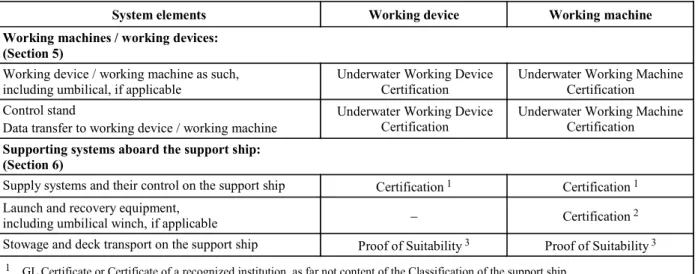
An overview which additional system elements are to be certified shows Table 1.1.
2.3 ROV/AUV Certificate
2.3.1 After completion and successful testing of the submersible a ROV Certificate will be issued for re-motely operated vehicles respectively an AUV Cer-tificate will be issued for autonomous vehicles by GL. 2.3.2 The Certificate certifies the technical condi-tion of the submersible at the time of the tests and approvals by GL. In addition it will be confirmed that no safety reservations are opposing the operation of the submersible.
2.3.3 The validity of the ROV respectively AUV Certificate is 5 years at maximum and can be pro-longed after renewed tests. For maintaining the Cer-tificate the submersible is in general to be subjected to an Annual Survey. The scope has to be agreed with GL in each single case.
The ROV respectively AUV Certificate looses its validity if substantial changes have been performed at the submersible respectively if the submersible has been severely damaged and the change or the repair has not been agreed and approved by GL.
3. Certification according to other rules 3.1 For unmanned submersibles, which are not built according to the Rules of GL, the applied rules have to be defined in a binding way in the application for Certification.
3.2 After successful examination a Certificate may be issued by GL.
I - Part 5
Table 1.1 Certification and Classification of unmanned submersibles
Types of unmanned submersibles System elements
ROV AUV Submersibles:
(Sections 1 – 4)
Submersible as such, including umbilical/lifting cable,
if applicable ROV Certification Classification AUV Certification Classification Control stand,
data transfer to submersible
Classification ROV Certification
Classification AUV Certification Launcher, if applicable ROV Certification Classification AUV Certification Classification Supporting systems aboard the support ship:
(Abschnitt 6)
Supply systems and their control Certification 1 Certification 1
Launch and recovery equipment,
umbilical winch, if applicable Certification 2 Certification 2
Stowage and deck transport Proof of suitability 3 Proof of suitability 3
1 GL Certificate oder Certificate of a recognized institution, as far not content of the Classification of the support ship 2 GL Certificate oder Certificate of a recognized institution
3 e.g. test stamp, test mark for lashing devices, etc.; proof for winches, deck fastening, etc.
C. Classification and Characters of Classifi-cation
1. Classification
1.1 Opportunity for Classification
Unmanned submersibles (UUV) may be classified and have then to be subjected to repeated surveys by GL according to the duration of Class.
1.2 Basis for Classification
These Rules for Classification and Construction con-stitute the basis for the Classification and Construction of unmanned submersibles.
For requirements not defined in these Rules, the other Rules for Classification and Construction of GL have to be applied, if not otherwise agreed.
The term "Rules for Construction" includes Rules for Materials and Welding as well as other Rules for Con-struction issued by GL, compare Section 2, B.
1.3 Scope of Classification
Classification comprises the entire unmanned sub-mersible including its machinery, structural elements and electrical equipment.
Anoverviewwhichadditionalsystemelementsofthe to-talsystemaregenerallytobeclassifiedshowsTable1.1. 1.4 Class Certificate
The Certificate of Classification for unmanned sub-mersibles is issued by the GL Head Office. It is to be kept on board of the support ship.
1.5 Class Register
Unmanned submersibles classified by GL are entered in the Register Book with a note of the Character of Classification and of the most important technical data and are included in the list of submersibles.
1.6 Operational records
Unmanned submersibles are required to carry an op-erational record in which details of operations (diving depth, mission time, damages, maintenance, repairs, etc.) are to be entered. The record is to be presented to the GL Surveyor on request.
2. Characters of Classification 2.1 The Character of Classification is:
– 100 A 5 ROV for remotely operated submersi-bles
– 100 A 5 AUV for autonomous operating sub-mersibles
The figure 5 denotes the duration of Class in years. 2.2 Where unmanned submersibles are built under the survey and in accordance with the Rules of GL using materials and components tested by GL in conformity with its Rules the Character of Classifica-tion is amended by the preceding Character .
2.3 Where unmanned submersibles are built under the survey and in accordance with the rules of another recognized classification society on being awarded GL Classification, the Character of Classifi-cation is amended by the preceding Character . Chapter 3
2.4 For submersibles and their equipment which are non-standard design, GL reserve the right to im-pose additional tests, to order a special survey sched-ule and to make special entries in the Certificate of the submersible and the Register Book.
3. Further class relevant requirements Further requirements for Classification and mainte-nance of Class are contained in the GL Rules for
Manned Submersibles (I-5-2), Section 1 and Clas-sification and Surveys (I-0) and are to be applied as far as possible analogously for unmanned submersibles. 4. Type approval for series vehicles
Unmanned submersibles which are manufactured in series may be subjected to a type test and certified or classified in a relevant way.
Kind and scope of the type tests as well as of the addi-tional construction supervision of the series are to be agreed with GL in each single case.
D. Surveys for Maintenance of Class 1. General
1.1 Surveys to be performed in the course of the constructional tests and acceptance tests on the un-manned submersible are performed by GL in accord-ancewiththeseRulesinagreementwiththe manufac-turer or operator. For this scope see Section 2, F. 1.2 Surveys required under official regulations, international conventions or other arrangements are performed by GL on application or commission as required by the relevant provisions.
1.3 If the submersible has suffered substantial damage which impairs or nullifies the validity of the Certificate, GL will on application carry out damage and repair surveys and confirm the Certificate after the necessary repair measures have been performed. 1.4 Extraordinary surveys have to be carried out if modification is made in respect of design, mode of operation or equipment.
1.5 If it is an excessive effort to prepare units and components for survey on board, the surveys may also, on application, be performed at the manufac-turer's works or another authorized workshop. 2. Class surveys
The surveys are to be performed according to the following criteria. If the operational systems of a sub-mersible should be different from the standard case, the scope of the surveys may be adjusted accordingly in agreement with GL.
2.1 Annual Survey
The Annual Survey of the unmanned submersible includes at least the following tests and checks:
2.1.1 Examination of the documents relating to the submersible and scrutiny of the operational records. 2.1.2 The exostructure including the load bearing structure, all fixtures, doors and covers, lifting points, claddings, fixed buoyancy aids, etc. are to be in-spected for visible damage, cracks, deformation, cor-rosion attacks and fouling, etc.
2.1.3 Check of the measures for corrosion protec-tion (e.g. anodes).
2.1.4 All vessels and apparatus under external or internal overpressure, penetrations, viewports, valves, fittings and relevant safety equipment are to be sub-jected to external inspection.
2.1.5 The entire machinery installation including electrical equipment and eventual redundancy systems are to be subjected to external inspection.
2.1.6 Check that insulation measurements have been performed on the electrical equipment.
2.1.7 Review of safety systems and of the set points of the safety devices.
2.1.8 Function test of all alarm systems.
2.1.9 Switching from the main to the emergency electricity supply of the submersible, if existing, is to be tested.
2.1.10 The accuracy of all essential instrument read-ings is to be checked (e.g. depth gauge, etc.).
2.1.11 All emergency systems (e.g. release mecha-nism, emergency signals) are to undergo a functional test - as far as applicable.
2.1.12 Check of the ballast system.
2.1.13 Hoseassemblies are to be checked for visible damages.
2.1.14 The umbilical and lifting cable - if applicable - is to be checked for visible damages, cracks, defor-mations and corrosion.
2.1.15 The function of the equipment for data trans-fer is to be checked.
2.1.16 The functional efficiency of the total system is to be checked by means of a trial dive.
2.2 Intermediate Survey
The Intermediate Survey falls due nominally 2,5 years after commissioning and each Class Renewal and may be carried out on the occasion of the second or third Annual Survey.
I - Part 5
An Intermediate Survey is an Annual Survey accord-ing to 2.1 extended by the followaccord-ing scope:
2.2.1 Performance of a tightness test on vessels under external pressure by application of a vacuum of at least 0,2 bar below atmospheric pressure or other suitable test procedures, as far as applicable.
2.2.2 Tightness test of ballast water system, if existing.
2.2.3 Tightness test of hose assemblies.
2.2.4 External visual check and eventual functional test, if applicable, of the extension elements/working devices belonging to the submersible.
2.3 Class Renewal Survey
Every five years a Class Renewal Survey will be car-ried out. In addition to the surveys defined in 2.2 the following tests and examinations are to be carried out for Class Renewal Surveys:
2.3.1 Check of the shell cladding and buoyancy aids (pressure resistant foam) from all sides. If neces-sary the cladding has to be removed.
2.3.2 Check of the areas of the load bearing struc-ture which are not easily accessible with the aid of non-destructive test procedures.
2.3.3 Forvesselsandapparatusunderpressure,which cannotbesatisfactorilyinspectedinternallyortheir satis-factory condition cannot be fully verified by internal inspection,anothernon-destructivetestmethod is to be used or a hydraulic pressure test is to be performed additionally. As far as necessary buoyancy materials, cladding or heat insulation layers are to be removed. 2.3.4 Acrylic windows are to be dismantled, if necessary, and are to be checked for cracks. The win-dow seatings are to be checked for corrosion and dam-ages.
2.3.5 Checkofsystemsforemergencysurfacingand the resulting floating condition at the water surface. 2.3.6 Check that accessories, especially hose as-semblies and compensators have been changed ac-cording to the maintenance plan.
E. Workmanship 1. General
1.1 Requirements to be complied with by the manufacturer and supplier
1.1.1 Each workshop of a manufacturer/supplier has to be provided with suitable equipment and facili-ties to enable proper handling of the respective
mate-rials, manufacturing processes, structural components, etc. GL reserve the right to inspect the workshops accordingly and ask for related requirements or to restrict the scope of manufacture to the potential available at the plant.
For safety relevant components and elements it is to be defined by GL if the manufacturer/supplier needs an approval by GL. Components and elements are regarded as safety relevant, if a direct danger for per-sons or the submersible may be created by them. 1.1.2 The manufacturing plants are to have at their disposal sufficiently qualified personnel. The supervi-sory and control personnel is to be named to GL, the areas of responsibility are to be defined. GL reserve the right to require proof of qualification.
1.2 Quality control
1.2.1 Themanufacturer/supplierhastoapplyaquality management system, like e.g. ISO 9001 or equivalent. 1.2.2 As far as required and expedient, all compo-nents both during manufacture and on completion are to be checked for completeness, correct dimensions and faultless workmanship according to the standard of good engineering practice.
1.2.3 Upon inspection and eventual corrections by the manufacturing plant, the structural components are to be presented to the GL Surveyor for inspection, in suitable construction sections, normally in uncoated condition and enabling proper access for inspection. 1.2.4 The GL Surveyor may reject components that have not been adequately pre-checked and may de-mand their resubmission upon successful checks by the manufacturer and, if necessary, corrective actions. 2. Details in manufacturing documents 2.1 All significant details concerning quality and functional ability of the component concerned shall be entered in the manufacturing documents (workshop drawings, etc.). This includes besides scantlings -
where relevant - such items as surface conditions (e.g. finishing of flame cut edges and weld seams), special methods of manufacture involved as well as inspection and acceptance requirements and where relevant per-missible tolerances.
Asfarasastandard(worksstandard,nationalstandard, etc.) shall be used it has to be harmonized with GL. 2.2 If, due to missing or insufficient details in the manufacturing documents, the quality or functional ability of the component cannot be guaranteed or is doubtful, GL may require appropriate improvements. This is valid analogously for supplementary or addi-tional parts (e.g. reinforcements), even if these were not required at the time of plan approval or if - as a result of insufficient detailing - could not be required. Chapter 3
Section 2
Principles for the Construction of Unmanned Submersibles
A. General Principles1. Wherever expedient and feasible, submersi-bles are to be designed and constructed in such a way that failure of any single component cannot give rise to a dangerous situation.
2. Submersibles and their components are to be designed to meet the service conditions stated in the specification.
3. Submersibles are to be designed and built to ensure safe operation and facilitate proper mainte-nance and the necessary surveys.
4. Submersibles are to be designed and con-structed in such a way that sufficient possibilities for monitoring during dived travels are given. This can be achieved e.g. by video systems and acoustic instru-ments.
B. Rules and Regulations to be Considered 1. Rules of GL
1.1 The following Rules are valid as additional requirements for the Certification/Classification and construction of submersibles in addition to the GL Rules for Classification and Construction of these vehicles:
– Part 0–Classification and Surveys
– Part1–SeagoingShips,Chapter1-4,ifapplicable – II – Materials and Welding, Part 1 - 3
1.2 For supporting systems aboard the support ship see Section 6.
1.3 Designs differing from the Rules of Con-struction may be permitted provided that they have been recognized by GL as equivalent.
1.4 Submersibles or parts thereof whose devel-opment is based on new principles and which have not yet been sufficiently tested in practical operation re-quire special approval by GL.
1.5 In the cases mentioned in 1.3 and 1.4, GL is entitled to require the submission of additional docu-mentation and the performance of special tests.
1.6 GLreservetherighttoimposedemands addi-tionaltothosecontainedintheRulesinrespect ofall typesofsubmersibleswhensuchactionisnecessitated bynewknowledgeorpracticalexperience,ortosanction deviations from the Rules in specially justified cases. 2. National regulations
National regulations existing alongside GL's Rules are unaffected.
3. International Conventions and Codes Where reference is made to international Conventions and Codes examples are listed in the following:
3.1 MARPOL 73/78
International Convention for the Prevention of Pollu-tion from Ships, 1973 including the 1978 Protocol as amended.
3.2 SOLAS 74
International Convention for the Safety of Life at Sea, 1974, as amended.
3.3 COLREGS 1972
International Regulations of 1972 to prevent collisions at sea.
C. Definitions 1. General
Autonomous submersible (AUV)
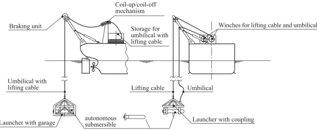
Submersible which is not physically connected to the support ship during operation (e.g. by an umbilical) and which is able to perform pre-defined missions with the aid of EDP-programming and active and/or passive sensors. Further on they are recovered by a support ship, supplied, maintained and transferred to the location of the next mission.
Control stand
Desk or console at which all essential indicators, con-trols, regulating devices, monitoring devices for the remote operation of the submersible are arranged. Diving pressure
The pressure, corresponding to the relevant diving depth, to which a submersible or diver is exposed during underwater operations.
I - Part 5
Exostructure
External fairing, supporting structures and fixtures outside of pressure vessels which are normally not designed to withstand the diving pressure.
Fixing system
Device for short time fixing of a submersible e.g. on a structure.
Garage
Cage into which the submersible can be launched and recovered in a protected way. The garage will in gen-eral be part of a launcher.
Gas cylinders
Bottles for the storage and transport of gases under pressure.
Launcher
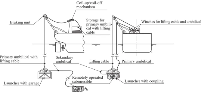
Device for launching and recovering of the submersi-ble from the support ship and from which the sub-mersible can start under water to the location of the mission. For remotely operated submersibles (ROV) the launcher is connected by lifting cable and rela-tively long supply lines with the support ship and contains normally the drum (e.g. TMS – Tether Man-agement System) for the umbilical from the launcher to the submersible.
Launching and recovering system
The plant and equipment necessary for launching and recovering a submersible.
Lifting cable
Cable for launching and recovering of submersibles and also for lifting and lowering of a remotely oper-ated submersible.
Payload NL of the submersible
Maximum additional load for devices, equipment, materials, which are not necessary for the direct opera-tion of the submersible, but are serving for work to be performed, investigation of the sea and scientific re-search.
Positioning system
System for keeping a pre-defined position (breadth, length, depth)
Pressure vessel
A container capable of withstanding an internal or external overpressure.
Remotely operated submersible (ROV)
Submersible which is during the mission physically connected to the related support ship by an umbilical and is controlled from there. As an exception also wireless remote control is possible.
Safe working load SWL of the launching and re-covery system
The safe working load SWL is the load which may be loaded directly to the launching and recovery system. The dead load of the load transmitting device which are not fixed to the launch and recovery system, but are used as connection between load and lifting appli-ance, are part of the safe working load SWL.
Supporting structure
Frame or rack in which the single components of the submersible are arranged together.
Supporting systems
Systems on the support ship, which are supporting especially remotely operated, but also autonomous submersibles with supplies necessary for the opera-tion, like e.g. electrical energy, hydraulic liquid, as well as control and monitoring data.
Support ship
A surface vessel for support and supply of remotely operated and autonomous submersibles. Within these Rules the support ship may also be a stationary supply station (e.g. on the coast or on a stationary offshore plant).
Total system
The submersible including its control, launching, recovery, storage, transport and supply systems. Umbilical
Connection between support ship and remotely oper-ated submersible, which might contain control, moni-toring, data transfer and energy supply lines and, if applicable, also a lifting cable.
This supply line can also be used between a launcher and the submersible or between the submersible and a diver.
Working device (underwater)
Device, e.g. manipulator, sample container and tools, which are fixed to the submersible and which are designated to the performance of underwater tasks and the reception of e.g. samples.
Working machine (underwater)
Machines, e.g. grab, driver, drill and their combina-tion, which are normally used from a support ship to perform underwater tasks.
2. Main dimensions and main parameters All dimensions are related to fix installed equipment in drawn-in/turned-in condition.
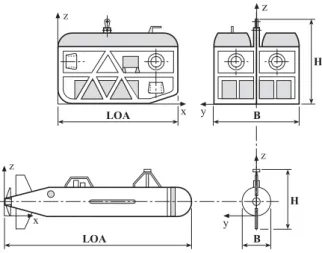
2.1 Co-ordinate system
In relation to the submersible a fixed, right-handed co-ordinate system x, y, z according to Fig. 2.1 is intro-Chapter 3
duced. The origin of the system is defined by the aft perpendicular, the centre line and the basis line of the submersible. The x-axis points in longitudinal direc-tion of the vehicle positive forward, the y-axis positive to port and the z-axis positive upwards. Angular mo-tions are considered positive in a clockwise direction about the three axes.
2.2 Length over all LOA
The length LOA is the length between the most for-ward and most aft point of the submersible including fixed installed components of equipment, measured parallel to the x-axis [m].
2.3 Total breadth (width) B
The total breadth (width) B is the maximum breadth of the submersible including all fixed installed parts of equipment, measured parallel to the y-axis [m]. 2.4 Radius of the pressure tight vessel Rm The radius Rm of a pressure tight vessel is the radius of the cylinder or the sphere related to the middle of the wall thickness [m].
2.5 Total height H
The total height H is the total height from baseline to upper edge of the vehicle including all fixed installed parts of equipment, measured parallel to the z-axis [m].
2.6 Draught T
The draught T in surfaced condition is the maximum vertical distance between the baseline and the water surface [m].
2.7 Displacement
The displacement of the surfaced submersible is Δ↑, the displacement of the dived vehicle is Δ↓ [t].
z x y z LOA B H y z H B x z LOA
Fig. 2.1 Fixed co-ordinate system and main di-mensions for remotely operated (above) and autonomous (below) unmanned sub-mersibles
2.8 Pay load NL
The maximum additional load for devices, equipment, materials, which are not necessary for the direct opera-tion of the submersible, but are serving for work to be performed, investigation of the sea and scientific re-search is NL [kg].
2.9 Diving depths
All diving depths are related to the baseline. 2.9.1 Nominal diving depth NDD
The nominal diving depth NDD is the diving depth for the unrestricted operation of the submersible [m]. 2.9.2 Test diving depth TDD
The test diving depth TDD is the diving depth which is related to an external overpressure, to which the submersible is subjected after the new construction or after essential repairs [m].
2.9.3 Collapse diving depth CDD
The collapse diving depth CDD is the diving depth of the submersible, which is adequate to the calculated external overpressure, where the collapse of a pres-sure-proof component is to be expected [m].
2.10 Velocities 2.10.1 Velocity v0↑
The velocity v0↑ is the maximum operational speed of
the surfaced submersible [kn] at a number of revolu-tions of the propeller according to the maximum con-tinuous propulsion power surfaced (MCR 1).
2.10.2 Velocity v0↓
The velocity v0↓ is the maximum operational speed of the dived submersible [kn] at a number of revolutions of the propeller according to the maximum continuous propulsion power dived (MCR 1).
D. Environmental Conditions 1. General
As a minimum requirement, the design, selection and arrangement of all machinery, instruments and equip-ment located on board submersibles are required to conform to the environmental conditions stated below. Environmental conditions other than those stated may be approved for submersibles for service only in par-ticular areas.
Forspecialmissions,likedivingundericeorincavesthe environmentalconditionsexperiencedtherearetobe con-sideredandthespecialmeasurestobeagreedwithGL. ––––––––––––––
1 MCR = maximum continuous rating
I - Part 5
2. Inclined positions
If not specified otherwise satisfactory functioning shall be ensured at (static and dynamic) inclinations of up to 22,5° in any direction measured in relation to the as-installed datum. Transient inclinations of up to 45° shall not adversely affect operation and shall not cause damage, particularly to machine mountings. For greater operational inclinations these have to be con-sidered adequately for design and testing.
3. Water
For the design of submersibles and components the temperature range of the water as well as the range of salt content and therefore of the density is to be de-fined. If not agreed otherwise, seawater with a tem-perature range from –2 °C to +32 °C, with a salt con-tent of 3,5 % and a density of 1028 kg/m3 may be used as a basis. A value of 0,101 bar/m is to be applied when converting diving depth to pressure.
4. Seaways
The seaways up to which the submersible shall be operated in surfaced condition are to be agreed with GL. If not agreed otherwise, submersibles are to be designed for sea states with a significant wave height of at least 2 m, allowance being made for accelera-tions of 2 g downwards and 1 g upwards in the vertical and 1 g each in the longitudinal and transverse direc-tions (g = 9,81 m/s2).
5. Tide and currents
For the design of the propulsion and manoeuvring arrangement the different influences of currents ac-cording to the operation area and their possible com-binations are to be considered.
As basis for the design the maximum as well as the minimum tide at the relevant operation area shall be included. In addition currents created by wind or geo-graphic specialities (e.g. narrow channels) are to be considered.
6. Climate
For transport, maintenance, inspection and trials out of water on board of support ships as well as for launch and recovery systems for the submersible salt impreg-nated air ranging in temperature from –10 °C to +55 °C at an relative atmospheric humidity of 100 % is to be considered.
In specially protected control rooms for remotely operated submersibles on board of support ships, a relative atmospheric humidity of 80 % at a reference temperature of 45 °C is to be considered.
7. Vibrations and shaking
Machinery shall not cause any vibration or shaking which imposes unacceptable stresses on other ma-chines, equipment or the hull of the submersible. The
amplitudes and accelerations defined in the GL Rules for Machinery Installations (I-1-2), Section 1, C. are to be complied with.
8. Explosion protection
Submersibles which are used in respectively from explosion endangered areas (e.g. of oil and gas deliv-ering platforms) are to be designed for the relevant explosion zones. This is also valid for control stands. 9. Further environmental conditions
For the design of the submersible also the environ-mental conditions occurring during an eventual air transport (e.g. underpressure/temperature) are to be considered.
E. Documents for Approval 1. General
1.1 Before the start of manufacture, plans of the total system and drawings of all components and sys-tems subject to compulsory inspection, wherever ap-plicable and to the extent specified below, are to be submitted to in triplicate respectively in case of elec-tronic transmission as single issue.
1.2 The documents shall contain all the data necessary to check the design and loading of the equipment. Wherever necessary, calculations relating to components and descriptions of the system are to be submitted.
1.3 Once the documents submitted have been approved by GL, they become binding for the execu-tion. Any subsequent modifications require GL's con-sent before they are implemented.
2. Total system
The following documents are to be submitted:
2.1 A description of the submersible with details of its mode of operation, the proposed application and the essential design data including e.g.:
– nominal diving depth
– maximum operating time and maximum func-tion time of identificafunc-tion signals
– maximum range of a mission (radius) – diving procedure
– operating limits for launching and recovery (seaway)
– other operating limits in relation to environ-mental conditions (e.g. salt water/fresh water or geographical peculiarities due to currents) Chapter 3
– speed below and eventually above water as well as maximum towing speed
– type of propulsion and manoeuvring equipment – type and extent of working devices and
equip-ment
– weight of vehicle, payload and ballast, dis-placement (submerged)
2.2 Generalarrangementdrawingandplans show-ing design details of the submersible, includshow-ing speci-fications for materials, manufacture and testing. 2.3 Drawings (block diagrams) of the total sys-tem.
2.4 Failure Modes and Effects Analysis (FMEA), if necessary.
2.5 A comprehensive presentation of the meas-ures taken to prevent corrosion.
2.6 Stability documentation (according to aim of mission and design)
2.7 Manual for operation and maintenance The manual for the operation shall include in detail the steps necessary for normal operation as well as for emergency operation in a clear and conceptual form and in the necessary sequence (e.g. as checklist). In addition the measures for the loading of the operating systems (e.g. batteries) are to be defined. In addition the planned lifetime as well as the permissible load and mission cycles of parts of the equipment (e.g. acrylic windows, batteries) is to be defined herein. The maintenance manual shall include all procedures for preventive maintenance as well as for periodic inspections.
2.8 Operational records
Allconditionsrelevantforoperation(divingdepth, mis-sion time, damages, etc.) are to be documented herein. 2.9 Trial program.
3. Supporting structure and exostructure Drawings of the supporting and exostructure of the submersible are to be submitted with data concerning extensions like trimming weights, diving cells, pres-sure vessels, buoyancy elements, stabilizing fins, drives, umbilical connection, control box, search lights, ram protection, fairing, manipulators, fixing systems, instrument racks, etc.
4. Vessels and apparatus under pressure Drawings of the vessels and apparatus under external and internal pressure are to be submitted with all es-sential particulars and details necessary for appraising the safety of the equipment and including the specifi-cations for materials, manufacture and testing.
5. Piping systems, umbilicals, and pumps The following are to be submitted:
5.1 Schematic diagrams of all piping systems including details of:
– materials
– maximum allowable working pressure – maximum allowable working temperature – dimensions (diameter, wall thickness) – media carried
– type of valves and connections used and their operational parameters
– type of hose assemblies
5.2 Description of pumps and their drives to-gether with all important design and operating data. 5.3 Description of the design of the umbilical and its single elements as well as the requirements for lifting cables according to Annex E, C.
5.4 Listing of the components filled with liquids with definition of the type of liquid (e.g. oil, water). 6. Diving, compensation and trimming
sys-tems
6.1 Submission of arrangement of diving, regu-lating and trimming systems with mathematical proof of the static diving capability
6.2 For open and closed loop control are to be submitted:
– description of the systems for depth, positive and negative buoyancy and trim including the necessary diagrams and component drawings – data concerning scope, type and design of
buoy-ancy and ballast elements and their fixing on the supporting structure
7. Propulsion and manoeuvring equipment Drawings and descriptions of the propulsion and ma-noeuvring equipment are to be submitted with data about:
– mode of operation and control of the systems – power demand (type and quantity)
– method of power transmission to propulsion unit – safety systems
8. Positioning system
– The type and control of the positioning system is to be explained.
I - Part 5 GL 2009
Section 2 Principles for the Construction of Unmanned Submersibles Chapter 3 Page 2–5 E
9. Working devices (compare also Section 5, G.)
9.1 For extension elements and working devices the effects on the total system are to be defined. 9.2 Plans and descriptions of the working devices provided are to be submitted with data concerning: – task of the devices/mission parameter – type of operation and energy supply – control and monitoring
– safety arrangements
– location and fixing at the supporting structure – applied materials
– type of release system, if applicable
9.3 Plans and descriptions of the fixing system are to be submitted with information for
– type and control of the fixing system – size of holding power
– behaviour at energy failure – type of release system 10. Electrical equipment The following are to be submitted:
10.1 A general arrangement drawing of the elec-trical equipment containing at least the following information:
– voltage rating of the systems
– powerresp.currentratingsofelectricalconsumers – switchgear and safety systems (e.g. overload
protection) with indicating settings for overload and overload protection
– cable types and cross-sections
10.2 The energy balance of power supply.
10.3 Plans and descriptions of the electrical energy supply system.
10.4 Drawings of switchgear and distribution equipment with parts list.
10.5 Complete documentation for electric motor drives with details of control, measuring and monitor-ing systems.
10.6 Battery installation drawing with details of battery types.
10.7 Details of electrical penetrations through pressure vessel walls.
10.8 Calculation of short-circuit conditions of all electrical components and distribution systems (e.g. power switches, power protection switches and fuses with data about the current ratings and breaking ca-pacity).
10.9 For the operation in explosive endangered areas the required explosion classes are to be proven. 10.10 Description of the electrical design of the umbilical as well as the connection to the submersible. 11. Automation, navigation and locating
sys-tems
The following are to be submitted:
11.1 Description of the complete layout of the instruments at the control stand of remotely operated submersibles.
11.2 Description of the control and operating ele-ments for the submersible and its equipment.
11.3 Description of the nautical and diving in-strumentation, including speed and position indicators. 11.4 A description of the safety and alarm sys-tems.
11.5 Arrangement drawings/block diagrams of monitoring systems including lists of measuring points.
11.6 Documentation for electronic components such as instrument amplifiers, computers and periph-eral units.
11.7 General diagrams and equipment lists for the data transmission systems and signalling equipment. 11.8 General diagram and description of the Video system.
11.9 Descriptions, general diagrams and equip-ment lists for the locating equipequip-ment.
12. Fire and explosion protection The following are to be submitted:
Description of preventive fire and explosion protec-tion measures for the submersibles which shall be used in or from explosion endangered areas.
13. Launcher
The following are to be submitted:
13.1 Plans and descriptions of the launcher with data about operating conditions, task and equipment. Chapter 3
13.2 Plans and descriptions of the garage system, if applicable, and equipment of the garage.
13.3 Description of the connections between the support ship and the launcher as well as between the launcher and the submersible.
F. Failure Modes and Effects Analysis (FMEA)
1. General
1.1 The Failure Modes and Effects Analysis (FMEA) has the purpose to identify possible failures in the total system, in subsystems and in components of unmanned submersibles/vehicles and to describe the effects on the total system and its subsystems resp. components.
1.2 For unmanned submersibles an analysis con-cerning the function and availability of the submersi-ble after occurrence of a single failure has to be sub-mitted if requested by GL.
1.3 The FMEA shall be executed in an early stadium accompanying the design to be able to realize system modification at due time. A tabular form, e.g. according to IEC 60812 is to be used.
2. Description of the subsystems relevant for the analysis
2.1 The FMEA shall represent an independent document and be understandable without consulting further documentation. This means that all relevant subsystems are to be described concerning the struc-ture of their basic functions, the installed redundancies and especially the interfaces of the subsystems to each other.
2.2 The description shall provide the operating personnel with a good overview of the vehicle struc-ture and the functionalities of the relevant subsystems. For all subsystems typical failure modes and their effects on the overall function of the vehicle shall be indicated. Further on the corrective actions to manage these failures and their effects are to be provided. 2.3 For unmanned submersibles the following subsystems are relevant for maintaining the overall function:
– exo-supporting structure and equipment – pressure hull penetrations and equipment – systems for control of depth, trimming, positive
and negative buoyancy
– vessels and apparatus under pressure
– pipingsystems,fittings,pumpsandcompressors, mainly for remotely operated vehicles (ROV) – Umbilicals, for ROVs
– propulsion and manoeuvring equipment – electrical installations
– emergency power supply
– control, automation, data transfer, navigation and locating equipment
– fire and explosion protection – launch and recovery system/launcher
– coil–up/coil–off mechanism for umbilicals, for ROVs
– mating equipment
– systems for control aboard the support ship – supply systems aboard the support ship – stowage and deck transport
– rescue systems
The system descriptions are to be completed by block diagrams according to 3.
3. Block diagrams of the relevant subsystems For each relevant subsystem a block diagram is to be established. This block diagram shall contain the es-sential information of the system required for the failure analysis, which is normally:
– definition of the subsystems
– all essential components of the subsystems – interfaces between the components of the
sub-systems
– interfaces to or from other subsystems (typical for hydraulic drives and controls, etc.)
– arrangements for control of the total system submersible
– supplies from outside the total system vehicle, if applicable
– further aspects depending on the actual design of the submersible
4. Analysis of the different relevant subsys-tems
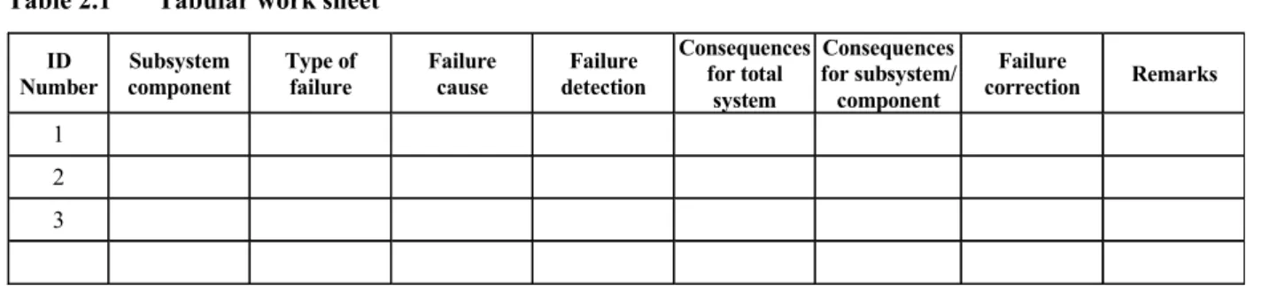
Each relevant subsystem is to be analyzed with regard to the following essential aspects, in course of which further aspects may occur during the execution of the analysis, compare work sheet (Table 2.1):
– failure of subsystems
– malfunctions of subsystems – failure of components in a subsystem – malfunctions of components
I - Part 5
Table 2.1 Tabular work sheet ID Number Subsystem component Type of failure Failure cause Failure detection Consequences for total system Consequences for subsystem/ component Failure correction Remarks 1 2 3
– interface failures between the subsystems, a sub-system and its components as well as between components themselves
Interfaceanalysisisveryimportant,asaccordingto experiencemanyfailuresarecreatedduetolackof knowledgeofwhichdata,mediumandpowerare transferredorhowfailuresarespreadviathe inter-faces to other subsystems/components.
– hidden failures
check for hidden failures and the practicality of alarms
arrangement of periodic testing where alarms are not practical
– failuresbecauseofexternalinfluenceswhichmay lead tosimultaneous failureofredundant subsys-tems, e.g. changed environmental conditionsand theircontrol,voltageandamperagefluctuationsin powersupply,contaminationofsupplymedia,etc. – faulty operation of subsystems or components,
only with certain probability 5. Tabular work sheet
The analysis shall be carried out in tabular form with a work sheet acc. to Table 2.1 or e.g. acc. to IEC 60812. The analysis has to consider all operational modes. 6. Assumptionsanddefinedlimitsfortheanalysis During the analysis the assumptions are to be defined which influence the result of the analysis. Typical assumptions are e.g.:
– the operating personnel is qualified and trained to safely operate the unmanned vehicle
– the supply of energy and as far as necessary with other consumables from outside the unmanned submersible is secured in redundant way (for re-motely operated vehicles - ROV)
– the settings and switching operations prescribed in the operation manual are followed by the op-erating personnel, etc.
7. Treatment of changes
In case of changes at the vehicle respectively at the supporting systems aboard the support ship the FMEA is to be adjusted.
8. Conclusions
The FMEA shall contain a summary of the results of the analysis for the relevant unmanned submersible. In addition it should contain a listing of the main failures which may occur for the operation of the vehicle and especially for keeping the manoeuvrability and ability for surfacing as well as the desired atmosphere in the pressure hull. For the operating personnel aboard the support ship training measures for incontestable han-dling of the vehicle and the supporting systems in the event of such failures are to be proposed.
A periodic check of the FMEA including practical trials is recommended.
9. FMEA test program
9.1 According to the FMEA a test program is to be established. The purpose of this program is to verify the assumptions and the expected operational behav-iour of the submersible as defined in the analysis. 9.2 The program has to consider typical failure modes in the relevant systems and components includ-ing the worst case failure. All operational modes of the vehicle are to be reflected.
9.3 The test program is to be agreed with GL and needs to specify in detail how the test shall be carried out respectively how simulation is done.
G. Tests and Trials 1. General
1.1 Unmanned submersibles are subject to con-structional and acceptance testing at the manufacturer’s works. As a minimum requirement, this shall include verification of compliance with the approved docu-ments, inspection of workmanship, proofs for materials and observance of dimensional tolerances. Wherever applicable all the tests prescribed in the following are to be performed and documented. About the presence of GL Surveyors at these tests and trials GL will decide case by case.
1.2 Forseries-manufactured parts,testprocedures other than those prescribed may be agreed with GL provided that they are recognized as equivalent by GL. Chapter 3
1.3 GL reserve the right to extend the scope of the tests where necessary and also to subject to test those parts for which testing is not expressly prescribed in the Rules.
1.4 Approved parts subject to replacement are to be replaced with tested parts. The same also applies to spare parts.
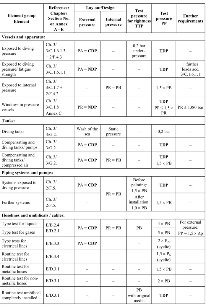
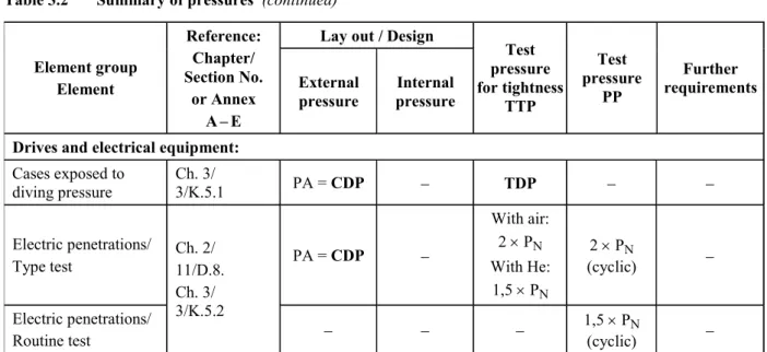
1.5 A summary of the test pressures, as well as of the design and lay-out pressures is contained in Section 3, C., Table 3.2.
2. Total system
On completion, the submersible is to be subjected to a constructional, functional and acceptance test. This shall include at least the following individual tests: – inspection of assembly (where not already
per-formed during checking of manufacture) – measurement of weight, buoyancy and stability – testing of all safety devices
– functional testing of diving and trimming equip-ment
– functional testing of mechanical, electrical and optical equipment
– functional testing of working devices including the fixing system with regard to influence on the submersible
– trial trip submerged
– testing of launch and recovery procedures includ-ing functional test of the launcher
– verification of all essential measuring instru-ments
– insulation test and if necessary high voltage test and on the electrical equipment
– test of the control stand on the support ship – trials and functional tests under water with diving
depths up to the nominal diving depth NDD 3. Supporting structure
3.1 It has to be checked, if the not pressure-proof parts of the supporting structure (hollow bodies, pipes, etc.)arepressureequalized. Pressure-proof components are to be tested according to 4.3.
3.2 The lifting points at the submersible are to be tested statically with 2,2 times the safe working load SWL (= weight and payload NL of the submersible). 3.3 The fixing point of the umbilical at the sub-mersible is to be tested statically with 2,2 times the maximum permissible tension load of the umbilical.
4. Vessels and apparatus under pressure 4.1 Pressure vessels are to undergo a hydraulic pressure test before being insulated or painted. The test may result in no leakage or permanent deformation of the vessel walls.
4.2 The test pressure applied to vessels and appa-ratus with stress from internal pressure shall generally be equivalent to 1,5 times the maximum allowable working pressure PB.
4.3 Vessels and apparatus which may be sub-jected to external overpressure according to the maxi-mum allowable diving depth of the submersible have to undergo an external pressure test. The test pressure TDP shall be at least a multiple of the nominal diving pressure NDP according to Table 3.1 in Section 3, C. 4.4 If the strength against pressure of vessels and apparatus cannot be sufficiently proven by calculation, an alternative verification has to be agreed with GL. 4.5 Allwindowsinpressurevesselsaretobe sub-jectedtoahydraulicpressuretest.Thetestmaybe per-formedafterinstallationtogetherwiththepressurevessel orstandaloneinatestdevice.Thetestpressureistobe determinedaccordingto4.3.Forthepressuretestithasto beobservedthatthatthetestpressureisnothigherthan 1,5 times the calculation pressure of the window. 5. Piping systems, umbilicals and pumps 5.1 Piping systems
5.1.1 On completion but before being insulated or painted, all piping systems are to undergo a hydraulic pressure test at 1,5 times the maximum allowable working pressure.
5.1.2 After installation, all piping systems are to undergo a tightness test at the maximum allowable working pressure. Pipes under diving pressure are to be checked in addition with test diving pressure TDP (inside or outside according to the actual load case). 5.1.3 The safety systems are to be checked. 5.2 Pumps
Oncompletion,pumpsaretobesubjectedbythe manu-facturertoapressuretestatthemaximumallowable work-ingpressure,atightnesstestaswellasaperformancetest. 5.3 Umbilicals/supply lines
Umbilicals of remotely operated unmanned submersi-bles (ROV) have to meet special requirements. The required tests are divided in a type test of the prototype and a routine test of the final product.
All aspects for the tests and trials of umbilicals are defined in Appendix E, D.
5.4 As far as the requirements in 5.3 are applica-ble for hose assemblies they shall be used.
I - Part 5
6. Trimming,compensatinganddivingsystems The trimming, compensating and diving systems are to be subjected to a functional test.
7. Propulsion and manoeuvring equipment Thefunctionofthepropulsionandmanoeuvringplantis to be proven at the occasion of trial travel under water. 8. Positioning system
The automatic keeping of a pre-defined position in breadth, length and depth is to be checked.
9. Working devices (See also Section 5, H.)
9.1 The influence of the working devices on the total system is to be tested.
9.2 The working devices have to be checked at least with reference to:
– control and monitoring – functioning of safety devices
– avoiding dangers for divers and the submersible 9.3 The fixing systems are to be subjected to a function test where at least the following individual tests are to be performed with respect to:
– specified holding power of the fixing system – limitations of power and distance travelled of the
fixing systems as well as the directing of the ve-hicle
– simulation of an energy failure 10. Electrical equipment
10.1 Electrical machines and automation, alarm and safety systems including steering and control stands are to be tested in the manufacturer's works. The electrical systems are to be approved by GL, pref-erably type approved components are to be used. Kind and scope of type tests are to be defined by GL case by case on the basis of the GL Test Requirements for Electrical/Electronic Equipment and Systems (VI-7-2). 10.2 All electrical systems and equipment are to be inspected and tested before the submersible is put into service.
10.3 The set points and response thresholds of electrical protective devices are to be checked.
Depending on the type of device the electrical equip-ment of the vehicle, if possible, is to be subjected to a high voltage test and an insulation test with a test volt-age ≥ 500 V.
10.4 Electrical cables under external pressure are to be checked according to the electrical requirements for umbilicals defined in 5.3.
10.5 Electrical penetrations into vessels and appa-ratus under pressure and underwater plug connections are to be subjected to a type and routine test according to GL Rules for Manned Submersibles (I-5-2), Section 11, D.8.
10.6 All electrical equipment which is exposed to diving pressure shall be checked additionally for isola-tion after the first diving.
11. Automation, navigation and locating equipment
11.1 Indicating and monitoring systems are to be checked for the accuracy of their readings, their limit value settings and ergonomic arrangement according to the GL Rules for Automation (I-1-4).
11.2 Automation systems are to be checked for satisfactory performance under service conditions. 12. Launcher
12.1 The launching and recovery of the launcher including the submersible is to be checked in a func-tional test.
12.2 The lifting point of the launcher is to be tested with 2,2 times the safe working load. The device for harbouring the submersible to the launcher is also statically tested with 2,2 times the weight including payload NL of the submersible.
12.3 Theentranceandtheexitofthesubmersibleto orfromthelauncherrespectivelythegarage,ifexisting, istobetestedindivedconditionandafunctionaltestof all elements of the total system is to be performed.
H. Marking
1. Fittings, indicators and warning devices All essential valves, fittings, control elements, indica-tor and warning devices are to be provided with per-manent and seawater resistant markings.
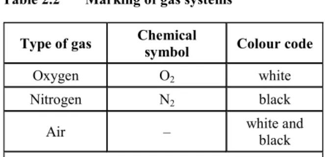
2. Pressure vessels and gas cylinders
2.1 All pressure vessels and gas cylindersare to be permanently marked at an easily visible position with the following details:
– name or company designation of manufacturer – year of construction and serial number (pressure
vessels)
– serial number (gas cylinders) Chapter 3