This is a summary document. The complete document is available under NDA. For more information, please contact your local Atmel sales office.
Features
Fully compliant to the Trusted Computing Group (TCG) Trusted Platform Module (TPM) version 1.2 specification
Compliant with TCG PC client-specific TPM Interface Specification (TIS) version 1.2 Single-chip, turnkey solution
Hardware asymmetric crypto engine Atmel® AVR® RISC microprocessor Internal EEPROM storage for RSA keys
33MHz Low Pin Count (LPC) bus for easy PC interface Secure hardware and firmware design and chip layout
Internal, high-quality Random Number Generator (RNG) – FIPS 140-2 compliant NV storage space for 1756 bytes of user defined data
3.3V supply voltage
28-lead thin TSSOP, 28-lead wide TSSOP, or 40-pad QFN packages Offered in both commercial (0 to 70°C) and industrial (-40 to +85°C)
temperature ranges
Description
The Atmel AT97SC3204 is a fully integrated security module designed to be integrated into personal computers and other embedded systems. It implements version 1.2 of the Trusted Computing Group (TCG) specification for Trusted Platform Modules (TPM). The TPM includes a cryptographic accelerator capable of computing a 2048-bit RSA signature in 200ms and a 1024-bit RSA signature in 40ms. Performance of the SHA-1 accelerator is 20μs per 64-byte block.
The chip communicates with the PC through the LPC interface. The TPM supports SIRQ (for interrupts) and CLKRUN to permit clock stopping for power savings in mobile computers.
Atmel AT97SC3204
Trusted Platform Module LPC Interface
1.
Pin Configurations and Pinouts
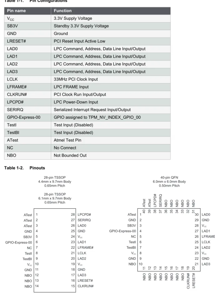
Table 1-1. Pin ConfigurationsTable 1-2. Pinouts
Pin name Function
VCC 3.3V Supply Voltage
SB3V Standby 3.3V Supply Voltage
GND Ground
LRESET# PCI Reset Input Active Low
LAD0 LPC Command, Address, Data Line Input/Output LAD1 LPC Command, Address, Data Line Input/Output LAD2 LPC Command, Address, Data Line Input/Output LAD3 LPC Command, Address, Data Line Input/Output
LCLK 33MHz PCI Clock Input
LFRAME# LPC FRAME Input
CLKRUN# PCI Clock Run Input/Output
LPCPD# LPC Power-Down Input
SERIRQ Serialized Interrupt Request Input/Output GPIO-Express-00 GPIO assigned to TPM_NV_INDEX_GPIO_00
TestI Test Input (Disabled)
TestBI Test Input (Disabled)
ATest Atmel Test Pin
NC No Connect
NBO Not Bounded Out
40-pin QFN 6.0mm x 6.0mm Body 0.50mm Pitch AT e s t AT e s t
LPCPD# SERIRQ NBO NBO NBO NBO NBO NBO
NBO NBO NBO NBO NBO NBO NBO NBO CLKRUN# LRESET# ATest GND SB3V GPIO-Express-00 NC TestI TestBI VCC GND NBO LAD0 GND VCC LAD1 LFRAME# LCLK LAD2 VCC GND LAD3 1 2 3 4 5 6 7 8 9 10 30 29 28 27 26 25 24 23 22 21 11 12 13 14 15 16 17 18 19 20 40 39 38 37 36 35 34 33 32 31 ATest ATest ATest GND SB3V GPIO-Express-00 NC TestI TestBI VCC GND NBO NBO NBO 1 2 3 4 5 6 7 8 9 10 11 12 13 14 28 27 26 25 24 23 22 21 20 19 18 17 16 15 LPCPD# SERIRQ LAD0 GND VCC LAD1 LFRAME# LCLK LAD2 VCC GND LAD3 LRESET# CLKRUN# 28-pin TSSOP 4.4mm x 9.7mm Body 0.65mm Pitch 28-pin TSSOP 6.1mm x 9.7mm Body 0.65mm Pitch
2.
Block Diagram
The TPM includes a hardware random number generator, including a FIPS-approved Pseudo Random Number Generator that is used for key generation and TCG protocol functions. The RNG is also available to the system to generate random numbers that may be needed during normal operation.
The chip uses a dynamic internal memory management scheme to store multiple RSA keys. Other than the standard TCG commands (TPM_FlushSpecific, TPM_Loadkey2), no system intervention is required to manage this internal key cache.
The TPM is offered to OEM and ODM manufacturers as a turnkey solution, including the firmware integrated on the chip. In addition, Atmel provides the necessary device driver software for integration into certain operating systems, along with BIOS drivers. Atmel will also provide manufacturing support software for use by OEMs and ODMs during initialization and verification of the TPM during board assembly.
Full documentation for TCG primitives can be found in the TCG TPM Main Specification, Parts 1 to 3, on the TCG Web site located at https://www.trustedcomputinggroup.org. TPM features specific to PC Client platforms are specified in the “TCG PC Client Specific TPM Interface Specification, Version 1.2”, also available on the TCG web site. Implementation guidance for 32-bit PC platforms is outlined in the “TCG PC Client Specific Implementation Specification for Conventional BIOS for TCG Version 1.2”, also available on the TCG website.
ROM Program EEPROM Program 33MHz LPC Interface GPIO GPIO-Express-00 AVR 8-bit RISC CPU SRAM EEPROM Data CRYPTO Engine RNG Timer Physical Security Circuitry
3.
Ordering Information
Note: 1. Please see the AT97SC3204 datasheet addendum for the complete catalog number ordering code.
Atmel Ordering Code Package Operating Range
AT97SC3204(1) 28X1 (28-pin thin TSSOP)
Lead-free, RoHS Commercial (0°C to 70°C) Industrial (-40°C to 85°C) AT97SC3204(1) 40ML1 (40-pin QFN)
Package Type
28X1 28-lead, 4.4mm body width, Plastic Thin Shrink Small Outline (thin TSSOP)
4.
Package Drawings
4.1
28X1 — 28-lead Thin TSSOP
TITLE
28X1, 28-lead, 4.4mm Body Width, Plastic Thin Shrink Small Outline Package (TSSOP)
GPC TFL DRAWING NO.
28X1
REV.A
e D E E1 15 14 28 1 CEND VIEW
SEE DETAIL "A"
CL
DETAIL 'A'
0.25 L (12° REF) (12° REF) (1.00 REF) R1 R STOP VIEW
(0°~8°) 2X N/2 TIPS d0.20 C B A B H D A A1 A2SIDE VIEW
SEATING PLANE C d0.10C j n0.10mC B A 28X b ASYMBOL MIN NOM MAX NOTE A A1 b D E E1 e L COMMON DIMENSIONS (UNIT OF MEASURE=MM) -0.05 0.19 -6.40BSC 1.10 0.15 0.30 1 A2 0.85 0.90 0.95 -c 0.09 - 0.20 9.60 9.70 9.80 4.30 4.40 4.50 0.45 0.60 0.75 0.65 BSC 1 2 R1 S R 0.09 - -0.09 - -0.20 - -Note:
2. Dimension D does not include mold flash, protrusions or gate burrs. Mold flash,protrusions or gate burrs shall not exceed 0.15mm per end. Dimension E1 does not include interlead flash or protrusion. Interlead flash or protrusion shall not exceed 0.25mm per side.
3. Dimension "b" does not include dambar protrusion. Allowable dambar protrusion shall be 0.08mm total in excess of the "b" dimension at maximum material condition. Minimum space between protrusion and adjacent lead is 0.07mm. 1. Refer to JEDEC drawing MO-153,variation AE
7/8/2011
Package Drawing Contact: [email protected]
4.2
40ML1 — 40-pad VQFN
DRAWING NO. REV.
TITLE GPC
Package Drawing Contact: [email protected]
40ML1 D
09/23/11
40ML1, 40-pad 6.0 x 6.0x0.9 mm Body, 0.50 mm pitch, Very-Thin Quad Flat No Lead Package (VQFN) Punched ZJI A1 A3 A A2 0
Side View
Notes: 1. This drawing is for general information only. Refer to JEDEC Drawing MO-220, Variation WJJD-2, for proper dimensions, tolerances, datums, etc.
2. Dimension b applies to metallized terminal and is measured between 0.15 mm and 0.30 mm from the terminal tip. If the terminal has the optional radius on the other end of the terminal, the dimension should not be measured in that radius area.
COMMON DIMENSIONS (Unit of Measure = mm)
SYMBOL MIN NOM MAX NOTE D 6.00 BSC E 6.00 BSC D2 4.10 4.30 4.40 E2 4.10 4.30 4.40 A - 0.85 0.90 A1 0.0 0.01 0.05 A2 - 0.65 0.70 A3 0.20 REF L 0.30 0.40 0.50 e 0.50 BSC b 0.18 0.23 0.30 2 D E
Top View
N 2 3 1 Pin 1 Indicator L PIN1 ID b N D2 3 2 1 eBottom View
E2 A B C 0.05 2X C 0.10 0.10 2X B A C C 0.10 C5.
Revision History
Doc. Rev. Date Comments
5295ES 03/2013 Removed bullet from features: 2048-bit RSA® sign in 200ms. Updated footers and disclaimer page.
5295DS 12/2012
Changed GPIO6 to GPIO-Express-00. Updated package drawings 28A3 and 40ML1. Updated package drawing 28A1 to 28X1. Updated template and Atmel logos. 5295CS 03/2011 Corrected header and footers. 5295BS 10/2010 Added Industrial Grade support detail. 5295AS 01/2008 Initial document release.
Atmel Corporation 1600 Technology Drive, San Jose, CA 95110 USA T: (+1)(408) 441.0311 F: (+1)(408) 436.4200 | www.atmel.com © 2013 Atmel Corporation. All rights reserved. / Rev.: Atmel-5295ES-TPM-AT97SC3204-LPC-Interface-Datasheet-Summary-032013
Disclaimer: The information in this document is provided in connection with Atmel products. No license, express or implied, by estoppel or otherwise, to any intellectual property right is granted by this document or in connection with the sale of Atmel products. EXCEPT AS SET FORTH IN THE ATMEL TERMS AND CONDITIONS OF SALES LOCATED ON THE ATMEL WEBSITE, ATMEL ASSUMES NO LIABILITY WHATSOEVER AND DISCLAIMS ANY EXPRESS, IMPLIED OR STATUTORY WARRANTY RELATING TO ITS PRODUCTS INCLUDING, BUT NOT LIMITED TO, THE IMPLIED WARRANTY OF MERCHANTABILITY, FITNESS FOR A PARTICULAR PURPOSE, OR NON-INFRINGEMENT. IN NO EVENT SHALL ATMEL BE LIABLE FOR ANY DIRECT, INDIRECT, CONSEQUENTIAL, PUNITIVE, SPECIAL OR INCIDENTAL DAMAGES (INCLUDING, WITHOUT LIMITATION, DAMAGES FOR LOSS AND Atmel®, Atmel logo and combinations thereof, Enabling Unlimited Possibilities®, AVR®, and others are registered trademarks or trademarks of Atmel Corporation or its subsidiaries. Other terms and product names may be trademarks of others.